1 - Erich Schmid Institute
1 - Erich Schmid Institute
1 - Erich Schmid Institute

Create successful ePaper yourself
Turn your PDF publications into a flip-book with our unique Google optimized e-Paper software.
A.4 Calculation Procedure and Results<br />
The actual stress distributions σi−1 and σi−1,i are depicted in Fig.A.7(f). The total<br />
stress distribution in the actual straightened system σi is calculated by adding σi−1 and<br />
σi−1,i. The resulting stress profile as well as the moment that compensates for σi and<br />
straightens the system Mi,s = −Mi are depicted schematically for i = 2 in Fig.A.7(g).<br />
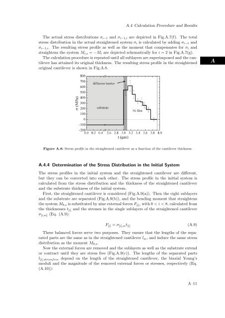
The calculation procedure is repeated until all sublayers are superimposed and the cantilever<br />
has attained its original thickness. The resulting stress profile in the straightened<br />
original cantilever is shown in Fig.A.8.<br />
Figure A.8: Stress profile in the straightened cantilever as a function of the cantilever thickness.<br />
A.4.4 Determination of the Stress Distribution in the Initial System<br />
The stress profiles in the initial system and the straightened cantilever are different,<br />
but they can be converted into each other. The stress profile in the initial system is<br />
calculated from the stress distribution and the thickness of the straightened cantilever<br />
and the substrate thickness of the initial system.<br />
First, the straightened cantilever is considered (Fig.A.9(a)). Then the eight sublayers<br />
and the substrate are separated (Fig.A.9(b)), and the bending moment that straightens<br />
the system M8,s is substituted by nine external forces F [i], with 0 < i < 8, calculated from<br />
the thicknesses t [i] and the stresses in the single sublayers of the straightened cantilever<br />
σ [i,sc] (Eq. (A.9):<br />
F [i] = σ [i],sct [i]<br />
(A.9)<br />
These balanced forces serve two purposes. They ensure that the lengths of the separated<br />
parts are the same as in the straightened cantilever lsc, and induce the same stress<br />
distribution as the moment M8,s.<br />
Now the external forces are removed and the sublayers as well as the substrate extend<br />
or contract until they are stress free (Fig.A.9(c)). The lengths of the separated parts<br />
l [i],stressfree depend on the length of the straightened cantilever, the biaxial Young’s<br />
moduli and the magnitude of the removed external forces or stresses, respectively (Eq.<br />
(A.10)):<br />
A–11<br />
A