1 - Erich Schmid Institute
1 - Erich Schmid Institute
1 - Erich Schmid Institute

Create successful ePaper yourself
Turn your PDF publications into a flip-book with our unique Google optimized e-Paper software.
C<br />
C A New Cantilever Technique Reveals Spatial Distributions of Residual Stresses<br />
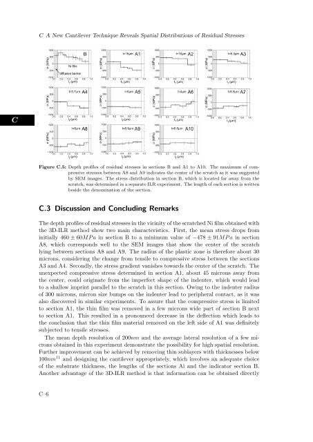
Figure C.5: Depth profiles of residual stresses in sections B and A1 to A10. The maximum of compressive<br />
stresses between A8 and A9 indicates the center of the scratch as it was suggested<br />
by SEM images. The stress distribution in section B, which is located far away from the<br />
scratch, was determined in a separate ILR experiment. The length of each section is written<br />
beside the denomination of the section.<br />
C.3 Discussion and Concluding Remarks<br />
The depth profiles of residual stresses in the vicinity of the scratched Ni film obtained with<br />
the 3D-ILR method show two main characteristics. First, the mean stress drops from<br />
initially 460 ± 60MP a in section B to a minimum value of −478 ± 91MP a in section<br />
A8, which corresponds well to the SEM images that show the center of the scratch<br />
lying between sections A8 and A9. The radius of the plastic zone is therefore about 30<br />
microns, considering the change from tensile to compressive stress between the sections<br />
A3 and A4. Secondly, the stress gradient vanishes towards the center of the scratch. The<br />
unexpected compressive stress determined in section A1, about 45 microns away from<br />
the center, could originate from the imperfect shape of the indenter, which would lead<br />
to a shallow imprint parallel to the scratch in this section. Owing to the indenter radius<br />
of 300 microns, micron size bumps on the indenter lead to peripheral contact, as it was<br />
also discovered in similar experiments. To assure that the compressive stress is limited<br />
to section A1, the thin film was removed in a few microns wide part of section B next<br />
to section A1. This resulted in a pronounced decrease in the deflection which leads to<br />
the conclusion that the thin film material removed on the left side of A1 was definitely<br />
subjected to tensile stresses.<br />
The mean depth resolution of 200nm and the average lateral resolution of a few microns<br />
obtained in this experiment demonstrate the possibility for high spatial resolution.<br />
Further improvement can be achieved by removing thin sublayers with thicknesses below<br />
100nm 11 and designing the cantilever appropriately, which involves an adequate choice<br />
of the substrate thickness, the lengths of the sections Ai and the indicator section B.<br />
Another advantage of the 3D-ILR method is that information can be obtained directly<br />
C–6