U 100-C - Astro
U 100-C - Astro
U 100-C - Astro

You also want an ePaper? Increase the reach of your titles
YUMPU automatically turns print PDFs into web optimized ePapers that Google loves.
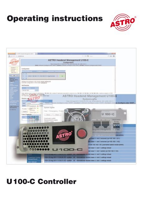
Operating instructions<br />
U <strong>100</strong>-C Controller
General<br />
This operating manual was created to provide the relevant instructions for operating the U<strong>100</strong>-C.<br />
We expressly recommend reading this manual before installing or operating the device.<br />
The ASTRO company confirms the information in this manual to be correct at the time of printing,<br />
but it reserves the right to make changes, without prior notice, to the specifications, the operation<br />
of the device and the operating manual. The ASTRO company is not responsible for printing<br />
errors. The contents of this operating manual are confidential and protected by copyright. This<br />
manual may not be reproduced in any form - not even in part - without prior written permission<br />
from the ASTRO company.<br />
Pictograms and safety instructions<br />
Pictograms are visual symbols with specific meanings. You will encounter the following pictograms<br />
in this installation and operating manual:<br />
Warning about life-endangering situations due to dangerous electrical voltage or non-adherence<br />
to this manual.<br />
Warning about various dangers to health, the environment and material.<br />
Recycling: all of our packaging material (cardboard boxes, accompanying papers, plastic film and<br />
bags) is completely recyclable.<br />
Used batteries must be disposed of at approved recycling points. Batteries must be completely<br />
discharged before being disposed of.<br />
Electronic devices must not be disposed of with household waste, but rather – according to directive<br />
2002/96/EG OF THE EUROPEAN PARLIAMENT AND OF THE COUNCIL from 27 January<br />
2003, on waste electrical and electronic equipment – must be properly disposed of. When they<br />
are no longer of use, please bring these devices for disposal to one of the public collection points<br />
for this purpose.<br />
Copyright notice<br />
Some of the software for this product is third-party software, which was developed under several<br />
different licensing conditions. Detailed information concerning the licenses can be found via the<br />
Web interface of the device.<br />
The source code of the free parts of the software is distributed on request for an administration<br />
fee.<br />
Please contact:<br />
kontakt@astro-strobel.de<br />
ASTRO Strobel Kommunikationssysteme<br />
Olefant 1-3<br />
D-51427 Bergisch Gladbach (Germany)<br />
Tel.: +49 2204 405/-0<br />
All other parts of the software of this product are copyrighted by <strong>Astro</strong> Strobel Kommunikationssysteme<br />
GmbH.<br />
© Copyright 2011 by <strong>Astro</strong>.<br />
2<br />
Operating Manual U <strong>100</strong>-C Controller
Table of contents<br />
1 Figures .........................................................................................................................................................4<br />
2 Introduction ........................................................................................................................................5<br />
2.1 Description of functions .....................................................................................................................5<br />
2.2 Safety instructions .............................................................................................................................5<br />
2.3 Mounting instructions ........................................................................................................................5<br />
2.4 Potential equalisation / earthing ........................................................................................................6<br />
2.5 Maintenance and repair ....................................................................................................................6<br />
2.6 Service tasks .....................................................................................................................................6<br />
2.7 Technical data for the mains supply (U <strong>100</strong> SNT - 230 V version) ..................................................6<br />
2.8 Installing and coding the backplane ..................................................................................................7<br />
2.8.1 Coding the backplane .......................................................................................................................7<br />
2.8.2 Installing the backplane .....................................................................................................................8<br />
3 General introduction ..........................................................................................................................9<br />
3.1 Connecting the U <strong>100</strong>-C to a PC / laptop .........................................................................................9<br />
3.2 Log in ...............................................................................................................................................10<br />
3.3 IP configuration ...............................................................................................................................10<br />
3.4 Time configuration ...........................................................................................................................11<br />
3.5 Setting up a user / Rights management / Log-in timeout ...............................................................12<br />
3.6 Logging the controller in to the U 1xx signal converter ...................................................................14<br />
3.7 Assigning system names ................................................................................................................14<br />
3.8 Adding U 1xx signal converters to the configuration .......................................................................15<br />
3.9 Removing U 1xx signal converters from the configuration .............................................................15<br />
4 Overview of the headend ................................................................................................................16<br />
4.1 Status display ..................................................................................................................................16<br />
4.2 Output channel overview / Channel overview .................................................................................17<br />
4.3 Material overview / Inventory report ................................................................................................17<br />
5 Log files ...........................................................................................................................................18<br />
5.1 Setting event filters in the system log file ........................................................................................18<br />
5.2 Saving and deleting the system log files .........................................................................................19<br />
6 Headend module settings / Module settings ..................................................................................20<br />
6.1 Active headend module settings / Active settings ..........................................................................20<br />
6.2 Stored headend module settings / Stored settings ........................................................................20<br />
6.3 Uploading locally stored module settings / Upload settings ............................................................21<br />
6.4 Monitoring the configuration / Configuration monitoring .................................................................22<br />
7 Switching equivalent head-end module circuits / Replacement ......................................................23<br />
7.1 Manual switching to equivalent circuits ...........................................................................................23<br />
7.2 Removing an equivalent circuit .......................................................................................................24<br />
7.3 Automatic equivalent circuit ............................................................................................................24<br />
7.4 Defining output segments / Output segments .................................................................................25<br />
8 SMNP settings .................................................................................................................................26<br />
9 Updating ..........................................................................................................................................27<br />
9.1 Uploading locally stored update archives to the U <strong>100</strong>-C controller ...............................................27<br />
9.2 FTP server download of update archives .......................................................................................27<br />
9.3 Displaying available update archives ..............................................................................................28<br />
9.4 Updating U 1xx headend modules ..................................................................................................29<br />
10 Setting up time-controlled processes ..............................................................................................30<br />
10.1 FTP server download of update archives .......................................................................................30<br />
10.2 Time-controlled update of U <strong>100</strong> headend modules .......................................................30<br />
11 Storing and loading the U <strong>100</strong>-C controller configuration ...............................................31<br />
12 Controller restart / Reset .................................................................................................32<br />
13 Technical data .................................................................................................................33<br />
Operating Manual U 110-C Controller<br />
33
230 V power unit<br />
48 V power unit:<br />
1 Figures<br />
The figures show the U <strong>100</strong>-C installed in the U <strong>100</strong> - 230 base unit together with<br />
the U 114 IP / PAL signal converters.<br />
Control<br />
and data wheel, menu switch<br />
Display of management IP addresses,<br />
data IP addresses, status messages, etc.<br />
Status display<br />
Mains supply<br />
Earthing connection<br />
Mains supply<br />
Cutout switch<br />
Mains supply<br />
Earthing connection<br />
4<br />
Management ports<br />
Status display<br />
for slots<br />
L = left<br />
M = middle<br />
R = right<br />
P = power supply<br />
Data ports<br />
HF outputs<br />
Fan<br />
Operating Manual U <strong>100</strong>-C Controller
2 Introduction<br />
The instructions in chapter 2 mainly apply to the U <strong>100</strong> - 230 base device.<br />
2.1 Description of functions<br />
The U <strong>100</strong> series is used to convert IP data streams into CATV signals. The U <strong>100</strong>-230 base<br />
device can accommodate up to three U 1xx signal converters, as well as up to two U <strong>100</strong>-SNTs<br />
for supplying the voltage to the U 1xx signal converters. The U <strong>100</strong>-C is used for comprehensive<br />
system management for the U 1xx signal converter, and provides many functions for configuring<br />
and servicing the U <strong>100</strong> series.<br />
2.2 Safety instructions<br />
Disconnect both mains plugs before opening the device!<br />
The device must not be opened - for exceptions, see the maintenance and repair, and the service<br />
tasks! Power supply units must not be opened!<br />
The device must be connected to a power supply with an earth contact, and should be positioned<br />
close to the mains socket.<br />
The electrical system supplying current to the device, e.g. a house installation, must incorporate<br />
safety devices against excessive current, short-circuiting and earth leakages in accordance with<br />
EN 60950-1.<br />
Both mains plugs are used to disconnect the device from the mains, therefore they must be<br />
easy to access and use at all times. The device is already in operation when one power unit is<br />
connected to the operating voltage. When the second power unit is also put into operation, one<br />
of the power units runs in idle mode as long as the other unit is supplying power to the device.<br />
The device may only be repaired by sending it to ASTRO along with a precise description of the<br />
error.<br />
Displays indicate the status of the device operation, as well as the existence of DC voltages<br />
separate from the mains that are supplying the components of the device. However, operation<br />
displays that are not lit up in no way indicate that the device is completely disconnected from the<br />
mains or is voltage-free.<br />
Read carefully:<br />
EN 50 083 – Part 1, Safety requirements / No service tasks during electrical storms!<br />
2.3 Mounting instructions<br />
The U <strong>100</strong> base device may only be mounted using guide rails! If the device is only fastened by<br />
means of the screws in the front panel, this will damage the base device!<br />
The outputs of the signal converter must not be operated without connecting a combining network<br />
or terminating impedance!<br />
Protection from environmental factors:<br />
The device must only be connected and operated in dry rooms. It must not be exposed to spraying<br />
or dripping water, or to similar phenomena. If condensation appears, wait until the device is<br />
completely dry. Objects containing liquid must not be placed on top of the device.<br />
The permitted ambient temperature range is 0 … 45°C (ETS 300 019-1-3 class 3.1).<br />
Mounting environment:<br />
The device is designed for operation in, preferably, metallically conductive 19" racks with sufficient<br />
air convection. It should be operated away from heat radiation and other heat sources. The<br />
device my only be installed in rooms in which the permitted ambient temperature can be adhered<br />
to, even under changing climatic conditions. To avoid trapped heat, it must be freely ventilated<br />
on all sides. You absolutely must avoid mounting the device in a niche or covering the ventilation<br />
openings.<br />
Operating Manual U 110-C Controller<br />
55
2.4 Potential equalisation / earthing<br />
The subscriber network must be earthed correctly in accordance with EN 50083-1, and must<br />
remain earthed even when the device is removed.<br />
The potential equalisation on the U <strong>100</strong> is effected via the fastening plates of the device, or<br />
via the earthing connection on the back of the device. Devices within hand's reached must be<br />
incorporated into the potential equalisation among one another.<br />
It is not permitted to operate the device without an earth conductor, device earthing or device<br />
potential equalisation!<br />
2.5 Maintenance and repair<br />
Disconnect both mains plugs before opening the device!<br />
The device must not be opened other than for repair purposes. In general, power units must<br />
not be opened. Repairs may only be carried out at the plant or at workshops, or by persons,<br />
authorised by ASTRO Strobel Kommunikationssysteme GmbH.<br />
Read carefully: DIN VDE 0701- 0702, Repairs<br />
Note: The device must not be opened by the user!<br />
2.6 Service tasks<br />
The following tasks, in which screw connections have to be opened, can be performed by appropriately<br />
instructed service personnel: Removal and installation of signal converters (e.g. U 114)<br />
and power units, also when the U <strong>100</strong> is in operating mode.<br />
Replacing power units<br />
After the screws on the cover of the power unit chamber (ASTRO logo) are removed,<br />
the power units can be pulled out by hand, forwards along the mounting panel.<br />
When power units are being installed, there should be no contact with the ventilator or the fan<br />
grid,<br />
and only the mounting panel attached to the power unit should be used.<br />
When the tasks are complete, the cover of the power unit chamber must be replaced;<br />
continuous operation of the device is not permitted without this cover.<br />
Note: Do not put your hand or any objects into the power unit chamber.<br />
The U <strong>100</strong> must only be operated with the original power unit(s)!<br />
Replacing converter modules:<br />
Converter modules can be pulled outwards after the safety screw on the front panel<br />
has been unscrewed.<br />
2.7 Technical data for the mains supply (U <strong>100</strong> SNT - 230 V version)<br />
Mains voltage: <strong>100</strong> – 240 V<br />
Mains frequency: 50 / 60 Hz<br />
Current consumption: 1.4 – 0.7 A per power unit<br />
Protection class according to EN 60529: IP 20<br />
Permitted ambient temperature range: 0 … 45 °C<br />
Secondary fuse in U<strong>100</strong>-230: T3,15A L 250 V IEC 60127-2/3<br />
Secondary fuses in U114: SMD, various values<br />
6<br />
Operating Manual U <strong>100</strong>-C Controller
2.8 Installing and coding the backplane<br />
The scope of delivery of every U 1xx signal converter includes a backplane to create the physical<br />
connection between the signal converter and the base device. Both the mains HF connections<br />
and the network connections are connected to this backplane. The temperature controlled fan for<br />
cooling the U 1xx signal converter is located on the backplane.<br />
2.8.1 Coding the backplane<br />
To correctly define the position of the backplane, and thus the position of the related signal converter<br />
in the U <strong>100</strong> base device, the jumper on the board of the backplane, which is described in<br />
the following section, must be configured.<br />
Left Middle<br />
Right<br />
Jumper position<br />
left!<br />
Figure 1: Coding the backplane using the jumper<br />
Note:<br />
An incorrectly configured jumper leads to incorrect displays in the front LEDs.<br />
In addition, it is not possible to display a correct position on the Web user interface!<br />
Operating Manual U 110-C Controller<br />
No jumper!<br />
Jumper position<br />
right!<br />
77
2.8.2 Installing the backplane<br />
In its state on delivery, the back of the U <strong>100</strong> base device is covered with blind panels:<br />
Figure 2: Position of the blind panel on delivery of U <strong>100</strong><br />
To remove the blind panel, unscrew the two Phillips screws indicated in the above figure and<br />
remove the blind panel. The cables now visible must be connected to the backplane coded<br />
according to chapter 2.8.1, as shown in the following figure:<br />
Figure 3: Connecting the voltage supply and signal lines<br />
The backplane is now carefully inserted into the free slot of the U <strong>100</strong> base device and screwed in<br />
with the Phillips screws of the backplane. When doing so, ensure that the cables are not jammed<br />
and that the backplane can be installed in the housing with only a small amount of pressure.<br />
Figure 4: Correctly installed backplane<br />
8<br />
Phillips<br />
screws<br />
Operating Manual U <strong>100</strong>-C Controller
3 General introduction<br />
3.1 Connecting the U <strong>100</strong>-C to a PC / laptop<br />
When the operating voltage is applied, or after insertion in the slot of the base unit,<br />
the U <strong>100</strong>-C switches itself on automatically. Following a boot phase (approx. 90 seconds),<br />
the ASTRO logo appears in the display. The page “Network/Rack”, on which the IP addresses<br />
appear, is accessed by turning the control knob. If the device is connected to a PC / laptop via<br />
one of the network ports, and if the PC / laptop is suitably configured via the network settings, you<br />
can start configuring the U <strong>100</strong>-C after you enter the IP address in the address line of the web<br />
browser. The IP address is 192.168.1.70 (Mgmt A) or 192.168.5.70 (Mgmt B) in delivery state.<br />
After activating the IP address, a window appears as in the following example:<br />
U <strong>100</strong>-C menu<br />
Figure 5: Example view of the web browser interface before configuration<br />
The controller status appears on the left side of the screen, with the so-called rack view appearing<br />
underneath it, which reflects the view of the head end. Clicking on the required module in this rack<br />
view allows the respective module to be configured. The links from “Log in” to “User manual” lead<br />
to overview pages, and to the configuration of the controller explained in the following.<br />
The heading for the sub-item selected appears in the head line. Furthermore, the date, the time<br />
(UTC), the uptime, the software version and the hardware version appear here. There is the<br />
option of entering a name, location and contact address. This is done in the sub-menu “SNMP”.<br />
The display in the main window corresponds to the sub-menu selected. These could be overview<br />
pages (status, channel overview & inventory report), or controller configuration pages, or user<br />
interfaces for the respective signal converter U 1xx which has been selected.<br />
Operating Manual U 110-C Controller<br />
Main window<br />
Title bar<br />
9
3.2 Login<br />
In order to change the configuration of the U <strong>100</strong>-C, you will have to log in first. In its delivery<br />
state, the following access has been set up:<br />
Administrator access (required for configuring the controller):<br />
User name: admin<br />
Password: astro<br />
User access (required for configuring operation):<br />
User name: user<br />
Password: astro<br />
You must log in before the U 114 can be configured. This is done in the “Login” submenu.<br />
In the state on delivery, the login data is as follows:<br />
User: admin or user<br />
Password: astro<br />
Figure 6: Log in under “User authentication”<br />
Without the log in, only the status pages of the controller and the user interface of the respective<br />
module can be viewed. However, no changes can be made.<br />
3.3 IP configuration<br />
In its delivery state, the U <strong>100</strong>-C controller has the IP address 192.168.1.70 (Mgmt A) or<br />
192.168.5.70 (Mgmt B).<br />
Note:<br />
Please observe that when the IP management interfaces are connected to a network which is<br />
operational, address conflicts could occur.<br />
10<br />
Operating Manual U <strong>100</strong>-C Controller
Figure 7: Example view of the “Network settings”<br />
After successfully logging in, the network settings can be configured. These settings are:<br />
IP address (address), sub-network mask (netmask) and standard gateway (gateway).<br />
Changes are applied using the “Submit” button. Depending on the new allocation of the IP<br />
addresses, it may be necessary to adapt the IP settings of the PC / laptop to ensure access to<br />
the controller is possible.<br />
3.4 Time configuration<br />
The U <strong>100</strong>-C controller provides the option of configuring the system time. Observe that UTC<br />
(Universal Time Coordinated) is always used as a reference.<br />
The date is entered in the column “Day”, the month in the column “Month” and the year in the<br />
column “Year”. The time is entered in the column “Hour”, “Minute” and “Second”.<br />
The settings are applied using “Submit”. An unwanted setting can be reset using the “Reset<br />
form” button. In this case, the previous settings are displayed again.<br />
Along with manual time input, an NTP time server can be entered. If the configuration is valid,<br />
the time is received from this server. To set up this server, enter the IP address and press the<br />
“Add” button (+) in the column “Action”. Any NTP server already set up can be removed using<br />
(-).<br />
Operating Manual U 110-C Controller<br />
11
Figure 8: Setting the system time<br />
3.5 Setting up a user / Rights management / Log-in timeout<br />
The sub-menu “User administration” is used to set up users, assign user rights and set the log-in<br />
timeout.<br />
Figure 9: View of the user administration<br />
In delivery status, one user and one administrator have been set up on the U <strong>100</strong>-C (admin: user<br />
name = admin, PW = astro, and user: user name = user, PW = astro, see chapter 3.2, Log in).<br />
12<br />
Operating Manual U <strong>100</strong>-C Controller
A new user is set up in the first blank line underneath any users already created (e.g. line 3 in figure<br />
9). The user name is entered in the column “User”, the rights assigned in the column “Access”<br />
and the password is entered in the column “Password”. This password must be entered a second<br />
time in the column “'Retype password”.<br />
In the user administration, the user will encounter the following pictograms:<br />
=Edit user<br />
= Accept changes<br />
= Remove user<br />
= Add user<br />
Without log in:<br />
View of the status pages for the headend (status, channel overview and inventory report as well<br />
as log file and user manual) and view of the respective U 1xx signal converter, however without<br />
the option of changing settings.<br />
User log in:<br />
Operation and reconfiguration of the signal converter (no change to the IP settings), load / save /<br />
copy module settings to “Module settings”, equivalent circuit (replace) and update.<br />
Admin log in:<br />
Access to the configuration (sub-menu “Configuration”) for the headend, or e.g. adding or removing<br />
further modules and access to the IP settings of the controller (sub-menu “Network/Rack”).<br />
SNMP settings (sub-menu “SNMP”), creating and removing users in the sub-menu “Users”,<br />
changing the timeout.<br />
Changing all controller settings; access to all sub-menus. Full access to the signal converter U<br />
1xx. The management IP addresses for the signal converter cannot be changed using the controller.<br />
Note:<br />
The management IP addresses for the signal converter can only be changed after this converter<br />
has been removed from the controller configuration (see chapter 3.9) and direct access is made<br />
via the IP address of the signal converter.<br />
The timeout can be configured to between 1 minute and 59 minutes. This value is changed using<br />
the “Submit” button. The input can be reset again using “Reset form”. The previous value set then<br />
reappears.<br />
Operating Manual U 110-C Controller<br />
13 13
3.6 Controller log in to the U 1xx signal converter<br />
To ensure the controller can log in to the U 1xx signal converter for the headend, the module dialin<br />
parameters of the controller configured in the U <strong>100</strong>-C must match the dial-in parameters in<br />
the U 1xx signal converter. In default state, two accounts for the module log in have been set up:<br />
User account: user name: controller / password: astro<br />
Admin account: user name: admin / password: astro<br />
Figure 10: Module log in<br />
Each of these two accounts have also been set up as default settings on each U 1xx<br />
signal converter.<br />
Note:<br />
Changes to these account must also be made in the U 1xx signal converters. Otherwise, the U<br />
<strong>100</strong>-C controller cannot log in to the U 1xx signal converter.<br />
3.7 Assigning system names<br />
In the sub-menu “SNMP” the system names appearing the head line can be entered. These<br />
are “Name” (e.g. name of the network operator), “Location” (e.g. location of the head line) and<br />
“Contact” (e.g. contact person for the respective headend). The values entered here are not only<br />
visible in the table, but are also used as SNMP system information (see chapter 8, “SNMP”).<br />
Figure 11: Entry of the system information<br />
14<br />
Operating Manual U <strong>100</strong>-C Controller
3.8 Adding U 1xx signal converters to the configuration<br />
Note:<br />
Before signal converters U 1xx can be incorporated in the configuration for the U <strong>100</strong>-C, it must<br />
be ensured that all U 1xx feature different management IP addresses, and all base unit addresses<br />
for the U <strong>100</strong>-230 / -48 feature different values (see operating manual for the signal converter U<br />
1xx). If this is not the case, then not all modules will be imported into the configuration.<br />
Figure 12: View of the point “configuration” without modules added<br />
Using the example in figure 11, you can see how the table is structured using the configuration<br />
view without the signal converter U 1xx added:<br />
Column “Base”: display of the base unit address; column “Slot”: display of the slot; column “IP<br />
address”: display of the IP address of the respective module; column “Description”: information on<br />
the module type; column “Action”: button for removing the respective module from the configuration;<br />
column “Monitoring”: display of the module status.<br />
A module can be added under “Add modules” (fig. 13) by entering individual IP addresses, several<br />
IP addresses separated by a space, or an automatic search of a sub-network by the controller. If<br />
a search for a sub-network should be made in this form, then the address range must be entered<br />
in CIDR notation.<br />
CIDR notation means:<br />
Entry of the network address separated by a “/” from the suffix entered. The suffix<br />
specified the number of bits set in the network mask. For the example, this means:<br />
192.168.1.0 as the network address and 255.255.255.0 for the sub-network mask<br />
(binary: 11111111 11111111 11111111 00000000) with 24 bits set.<br />
Figure 13: Screen for entering the IP addresses of modules to be added<br />
3.9 Deleting U 1xx signal converters from the configuration<br />
To remove modules form the configuration of the U <strong>100</strong>-C, the “Remove module from configuration”<br />
button in the column “Action” must be pressed (see figure 13).<br />
Figure 14: Button for removing modules from the configuration<br />
Operating Manual U 110-C Controller<br />
15 15
4 Overview of the headend<br />
To simplify the overview of the modules connected to the U <strong>100</strong>-C, the U <strong>100</strong>-C features several<br />
overview pages. These overview pages can be accessed without logging in to the U <strong>100</strong>-C controller.<br />
Changes to the configuration are not possible here.<br />
4.1 Status display<br />
The status display can be accessed using the link “Status” in the left frame of the web browser<br />
user interface. The following view, an example, opens:<br />
Figure 15: Display of the headend status<br />
The details of the individual modules can be viewed using the plus sign in the column “Base”. The<br />
details on the status of the module concerned are displayed here (see figure 16).<br />
Figure 16: Status details<br />
16<br />
Operating Manual U <strong>100</strong>-C Controller
4.2 Output channel overview / Channel overview<br />
In the output channel overview, all output channels and frequencies used are listed, beginning<br />
with the lowest frequency. Using this overview, the output channels can be linked with the services<br />
converted and the slot of the U 1xx signal converter.<br />
Figure 17: Example of output channel overview / channel overview<br />
4.3 Material overview / Inventory report<br />
Using the material overview, which is accessed using the link “Inventory report” on the left side of<br />
the web interface screen, an overview can be gained of the modules of which the entire headend<br />
is comprised, and in which base unit – on which slot – which unit – is being used.<br />
In addition to this information, the order number of the respective module is specified in the column<br />
“Order no.”.<br />
Operating Manual U 110-C Controller<br />
17 17
Figure 18: Example of material overview / inventory report<br />
The hardware status of the respective device appears in the line “HW”, and in the line “SW”, the<br />
software status is shown. The “Uptime” is the length of time for which the device has been in<br />
uninterrupted operation. The line “Monitoring” specifies the status.<br />
5 Log files<br />
The log files can be accessed using the link “Log file”. In the system log file, all relevant processes<br />
concerning operation are recorded. Further log files can be downloaded:<br />
Download log file: Logs for downloads from update archives<br />
Replacement log file: Logs for equivalent circuits<br />
Update log file: Logs for updates<br />
5.1 Setting event filters in the system log file<br />
To manage the displayed entries in the log file, filters can be used to select which events are displayed. This is set in<br />
the line “Filter”. Activating the check box results in a display of an event with the respective severity level. An entry will<br />
be made in the log file.<br />
Figure 19: Event filter in the log file (delivery state)<br />
18<br />
Operating Manual U <strong>100</strong>-C Controller
5.2 Saving and deleting the system log files<br />
The log file can be stored using the “Save” button. The file with the content of the log file is generated<br />
as “system.log” as standard and can be viewed e.g. using an editor.<br />
The “Clear” button ensures that the system log file is deleted and that the entry “Log file cleared”<br />
appears in first place.<br />
Figure 20: Example view of the system log file page<br />
Operating Manual U 110-C Controller<br />
19 19
6 Head end module settings / Module settings<br />
The headend module settings can be accessed using the link “Module settings” on the left side<br />
of the web interface screen. On the U <strong>100</strong>-C, a general distinction is made between active and<br />
saved module settings.<br />
6.1 Active head end module settings / Active settings<br />
In the upper section of the sub-menu “Module settings”, the active headend module settings are<br />
displayed. The structure of the overview is similar to the way the headend is structured, by base<br />
unit (column “Base”), slot (column “Slot”) and module type (column “Module”).<br />
Figure 21: Excerpt from the active settings of an example base unit<br />
Furthermore, the IP addresses are displayed, the names of the files (column “Name”) and the<br />
date of the last change to the settings (column “Date”). In the column “Action” the diverse buttons<br />
explained in the following are available.<br />
= “Reload from Module”: re-import of the module data in the controller<br />
= “Upload to Module”: re-writing of the active settings<br />
= “Save to stored settings”: saves the active settings to the<br />
“Stored settings” field.<br />
Figure 22: Buttons in the “Active settings” field<br />
When the “Save to stored settings” button is pressed, an entry is made in the “Stored settings”<br />
field. A name is given according to the IP address management A formula: aaa.bbb.ccc.ddd.zip,<br />
can however be subsequently edited (see chapter 6.2).<br />
6.2 Stored head end module settings / Stored settings<br />
In the “Stored settings” field, the settings saved by the user for the respective headend modules<br />
can be found. In this view, all module configurations which were loaded to the controller manually<br />
are also displayed.<br />
Figure 23: Example view of the “Stored settings” field<br />
20<br />
Operating Manual U <strong>100</strong>-C Controller
To write stored module settings into an active headend module, the radio button in the first column<br />
of the saved setting required must be activated as well as the radio button in the first column in<br />
the “Active settings” field on the module required. The settings are written into the module using<br />
the “↑Activate” button.<br />
A graphic example showing a U 114 IP / PAL converter:<br />
Figure 24: Example for writing stored settings in active mode<br />
In the column “Action” the diverse buttons explained in the following are available.<br />
= “Rename Settings”: changes the name of the configuration<br />
= “Download Settings”: downloads the configuration / saves it locally<br />
= “Remove Settings”: deletes the stored settings from the controller<br />
Figure 25: Buttons in the “Stored settings” field<br />
6.3 Uploading locally stored module settings / Upload settings<br />
There is an option of uploading locally stored module settings onto the controller. This is done in<br />
the “Upload settings” field.<br />
Figure 26: Dialogue field “Upload settings”<br />
Using the “Search” button, a file-upload window is opened in which the selection of the configuration<br />
for upload is made.<br />
A successfully uploaded file is then displayed in the “Stored settings” field and can then, as<br />
described in chapter 6.2, be loaded to the headend module.<br />
Operating Manual U 110-C Controller<br />
21
6.4 Monitoring the configuration / Configuration monitoring<br />
In ongoing operation, the controller monitors the configuration of the modules. If the configuration<br />
of a module does not match the configuration filed under “Active settings”, then different procedures<br />
can be defined:<br />
Figure 27: Procedure when detecting “configuration not in sync”<br />
When the option “Warning” is used, only the warning “config not in sync” is issued, however no<br />
operative action is taken. If the option “restore replaced modules only” is selected, then the configuration<br />
is only reloaded to the module for equivalent-circuit modules (default). The third option<br />
is “restore always”, and every time a “configuration not in sync” is detected, the configuration will<br />
be reloaded to the module.<br />
The “Restore” function is equivalent to the same action as a manually-performed “Upload to<br />
module” (see chapter 6.1).<br />
22<br />
Operating Manual U <strong>100</strong>-C Controller
7 Switching equivalent head-end module circuits /<br />
Replacement<br />
The U <strong>100</strong>-C controller provides an option of manually or automatically switching the replacement<br />
module kept in the headend to an equivalent circuit. The settings for this equivalent circuit can be<br />
accessed using the link “Replacement” in the left screen side of the web interface.<br />
7.1 Manual switching to equivalent circuits<br />
Switching to an equivalent circuit manually is done in the “Replace” field. The options for the<br />
equivalent circuit are displayed here. A headend module is then identified as a replacement mod<br />
ule by the U <strong>100</strong>-C controller, if the HF outputs are configured to “Off”.<br />
Figure 28: Example view of the “Replace” option<br />
The modules deactivated on the HF are backlit in grey in the column “Status” in the view in figure<br />
27, and their status is “off”. Each of these replacement modules are available for selection in the<br />
column “Replace options”. Prerequisite for this is that the outputs in the same cable network have<br />
been bundled (see chapter 7.3 Output segments). To establish the equivalent circuits, the radio<br />
button in the required equivalent circuit option must be selected, and the “Replace” button must<br />
then be pressed. The U <strong>100</strong>-C controller then establishes the equivalent circuit automatically. This<br />
process is documented in the Replacement log file. The module used for the equivalent circuit will<br />
not appear in the column “Replace options” until the equivalent circuit is removed.<br />
Operating Manual U 110-C Controller<br />
23
7.2 Removing an equivalent circuit<br />
An active equivalent circuit can be identified in the “Replace” display, as in the following example:<br />
Figure 29: View of an equivalent circuit<br />
After rectifying a fault or e.g. replacing a module, the equivalent circuit can be reversed. This is<br />
done by activating the radio button “undo replacement” in the column “Replace options” and then<br />
pressing the “Submit” button. This procedure is necessary, regardless of whether the equivalent<br />
circuit was set up manually or automatically. The U <strong>100</strong>-C controller undoes the equivalent circuit<br />
if the operating module can be restarted without a fault. This process is also documented in the<br />
Replacement log file.<br />
7.3 Automatic equivalent circuit<br />
Figure 30: Conditions which must be activated for an automatic equivalent circuit<br />
24<br />
Operating Manual U <strong>100</strong>-C Controller
The U <strong>100</strong>-C controller provides the option, depending on the fault which has occurred, of establishing<br />
an equivalent circuit for the U 1xx signal converter. The conditions for this equivalent circuit<br />
are listed in figure 30 and vary depending on which U 1xx signal converter is in use. The selection<br />
is applied by pressing “Submit”.<br />
Note:<br />
Activating the options with *) should be given good consideration, as these fault patterns do not<br />
necessarily correspond to a signal failure, but rather may also indicate that the U 1xx signal converter<br />
cannot be reached. It is quite possible that these modules are still sending an HF output<br />
signal, and that in the event of an equivalent circuit a double allocation in the output channel will<br />
occur.<br />
7.4 Defining output segments / Output segments<br />
The individual headend modules can, in theory, be combined in different networks. This means<br />
that the U <strong>100</strong>-C controller must know in which network or which output segment the output signal<br />
is distributed. If this were not the case, then an equivalent circuit – without allowing for the output<br />
segments – could cause double channel allocations in the respective networks. In the example<br />
below, the replacement modules no. 6 can only replace module no. 5 as the physical HF wiring<br />
only fits together with module no. 5.<br />
Figure 31: Combining example with restricted equivalent circuit options<br />
Output segments can be created in the sub-menu “Configuration” which is accessed using the link<br />
of the same name in the left frame of the web interface.<br />
Figure 32: Creating different network segments<br />
In the first column in the section “Output segments”, the consecutive number of the output segment<br />
is displayed, in the column “Segment name”, the name of the respective network segment<br />
is displayed.<br />
Operating Manual U 110-C Controller<br />
25 25
The following buttons can be used in the column “Action”:<br />
= “Rename segment”: renames the network segment<br />
= “Remove segment”: removes a network segment<br />
= “Add segment”: adds a network segment<br />
Figure 33: Buttons in the “Output segments” field<br />
After defining one or more output segments, the column(s) “Output segments” will be added to<br />
the table in the “Configuration” field. The output segments can now be selected by activating the<br />
check boxes for the respective output segment used. The selection is applied by pressing “Submit”.<br />
Figure 34: Example view once output segments are defined<br />
8 SMNP settings<br />
Figure 35: SNMP settings page in delivery state<br />
26<br />
Operating Manual U <strong>100</strong>-C Controller
The settings in the “SNMP System information” field have already been described in chapter 3.7.<br />
The SNMP settings can be accessed using the link “SNMP on the left side of the web interface<br />
screen. The page which then opens is shown in figure 35. Along with the SNMP system information,<br />
SNMP trap receivers can also be set up. To do so, enter the IP address of the trap receiver<br />
and then use the “Add trap sink” button to copy this into the column “Action”.<br />
In the SNMP MIBs field both the ASTRO Strobel MIB as well as the <strong>Astro</strong>Strobel-Edge-CTRL<br />
MIB can be downloaded.<br />
9 Updating<br />
All information on updating the U 1xx signal converter and the U <strong>100</strong>-C controller itself can be<br />
found in the sub-menu “Update”. The sub-menu can be accessed using the link “Update” in the<br />
left frame of the web browser user interface.<br />
9.1 Uploading locally stored update archives to the U <strong>100</strong>-C controller<br />
To ensure that the U <strong>100</strong>-C controller can update the U 1xx signal converter in use, the update<br />
archive required must first be copied onto the U <strong>100</strong>-C controller. This can be done using the<br />
locally-stored archive, or using an FTP server download (see chapter 9.2).<br />
Figure 36: Dialogue field “Add archive”<br />
Using the “Search” button, a file-upload window is opened in which the selection of the archive for<br />
upload is made. A valid archive must be selected, as the controller checks the file and discards<br />
any invalid files.<br />
After successfully uploading, the update archive appears in the “Update archives” field and is<br />
available as an option for an update in the “U <strong>100</strong> headend update” field in the column “Update<br />
options” on the respective matching U 1xx signal converter.<br />
9.2 FTP server download of update archives<br />
Update archives can alternatively be downloaded from an FTP server.<br />
This feature is explained in the following using the ASTRO firmware server as an example:<br />
Figure 37: Input screen for downloading update archives from the server<br />
Operating Manual U 110-C Controller<br />
27 27
Line: Input:<br />
FTP Server address www.astro-firmware.de<br />
Mode Active or passive, depending on the Firewall setting<br />
FTP Username (e.g. anonymous) Anonymous<br />
FTP Password (e.g. guest) Guest<br />
Path /Headend-Firmware/u1xx/<br />
The entry is applied using the “Submit” button.<br />
Using the “Download” button, any update archives available are loaded from the server. This<br />
process can also be done to a schedule (see chapter 10). After successfully downloading, the<br />
update archive appears in the “Update archives” field and is available as an option for an update<br />
in the “U <strong>100</strong> headend update” field in the column “Update options” on the respective matching<br />
U 1xx signal converter.<br />
9.3 Displaying available update archives<br />
Available updates are displayed on the U <strong>100</strong>-C controller in the “Update archives” field. In its<br />
delivery state, the U <strong>100</strong>-C is equipped with an SD card. Memory space remaining on this card is<br />
indicated under “SD card memory”.<br />
28<br />
= = “Archive info”: version information information on SW releases<br />
= “Archive download”: download”: archive download and local<br />
Saving this downloaded archive<br />
= “Remove archive”: removes the archive from the U <strong>100</strong>-C<br />
Figure 38: View of the available archives on the U <strong>100</strong>-C / buttons<br />
Operating Manual U <strong>100</strong>-C Controller
9.4 Updating U 1xx headend modules<br />
After successfully uploading the update archive, these are available for updating the diverse U<br />
1xx headend modules or the U <strong>100</strong>-C. (see fig. 39).<br />
Figure 39: Example view of the “U <strong>100</strong> headend update” field<br />
After selecting the action(s) to carry out, the update can be started by pressing the “Update” button.<br />
The “Reset form” button resets the action selected beforehand. This process can also be<br />
done to a schedule using the “Schedule update(s)...” button (also see chapter 10).<br />
Operating Manual U 110-C Controller<br />
29 29
10 Setting up time-controlled processes<br />
The U <strong>100</strong>-C controller is able to run processes to a schedule. These processes are, on the one<br />
hand, a time-controlled update of the update archives found on the U <strong>100</strong>-C, and on the other<br />
hand, a time-controlled download of the same update archive.<br />
10.1 Time-controlled download of update archives<br />
The time-controlled download of update archives can be activated in the sub-menu “Update” in<br />
the “Server download” field. By pressing the “Schedule download” button, the following input window,<br />
shown as an example, is accessed:<br />
Figure 40: Setting up a time-controlled, weekly update<br />
In the example shown above, after the “Confirm” button is pressed, a weekly download of update<br />
archives occurs, every Monday at 07:55.<br />
If the link “Schedule” is now pressed in the left frame of the web interface, then the scheduled<br />
download which has been set up is displayed:<br />
Figure 41:<br />
Using the “Disable process” button in the column “Action”, the process can be stopped any time<br />
and then be restarted using the “Enable process” button. The “Remove process” button removes<br />
the process from the overview.<br />
10.2 Time-controlled update of U <strong>100</strong> head end modules<br />
The time-controlled update of U <strong>100</strong> headend modules is made in the sub-menu “Update” in the<br />
“U <strong>100</strong> headend update” field. To do this, each respective module for which a time-controlled<br />
update should be made must be marked using the radio button in the column “Update options”,<br />
and then by pressing the “Scheduled update(s)” button on it.<br />
In the following example, after the “Confirm” button is pressed, a one-time, non-recurring update<br />
of a U 114 IP / PAL signal converter occurs:<br />
30<br />
Operating Manual U <strong>100</strong>-C Controller
Figure 42: Setting up a time-controlled, one-time update<br />
This process also appears in the sub-menu “Schedule” and can be edited using the buttons<br />
described in chapter 10.1.<br />
11 Storing and loading the U <strong>100</strong>-C controller configuration<br />
Using the link “Load/save config” in the left frame of the web interface, the sub-menu for storing<br />
and loading the U <strong>100</strong>-C controller configuration can be accessed.<br />
Figure 43: Sub-menu “Load/Save config”<br />
If the “Save” button is pressed in the “Save controller configuration” field, then the U <strong>100</strong>-C controller<br />
configuration is saved. The file is automatically named according to the formula “Name<br />
(city).conf”. The variables “Name” and “City” are assigned in the sub-menu “SNMP” (see chapter<br />
3.7).<br />
When the “include module log files” check box is activated, both the controller configuration as<br />
well as the log file for the U 1xx headend modules are downloaded. This information can be evaluated<br />
at <strong>Astro</strong> for debugging purposes.<br />
In the “Load controller configuration” field the backed up, locally saved U <strong>100</strong> C configuration data<br />
can be exported into the controller. When securing these files, both the user accounts as well as<br />
the IP settings are secured. When the configuration is loaded, it is possible to choose whether<br />
these data should also be copied.<br />
Note:<br />
If the user accounts and network settings should be overwritten along with the specific configuration,<br />
then this may result in the headend being unreachable.<br />
Operating Manual U 110-C Controller<br />
31
12 Controller restart / Reset<br />
To restart the controller or to reset it to the factory default settings, you must switch to the corresponding<br />
sub-menu using the link “Restart/reset” on the left edge of the web interface. The<br />
following input mask appears:<br />
Figure 44: Input mask for controller restart/reset<br />
Selecting “Restart” will reboot the device, while retaining all settings.<br />
Selecting “Soft reset” deletes the current configuration of the U <strong>100</strong>-C. The network settings and<br />
user accounts will be retained.<br />
Selecting “Hard reset” restores the delivery state, i.e. the U <strong>100</strong>-C configuration, the network settings<br />
and user accounts will be deleted.<br />
Note:<br />
Selecting “Hard reset” may lead to the headend being unreachable by remote access.<br />
32<br />
Operating Manual U <strong>100</strong>-C Controller
13 Technical data<br />
Type U <strong>100</strong>-C<br />
Order number 380 103<br />
Network interfaces (forwarded passively to U 1xx)<br />
Protocol IEEE802.3 Ethernet, RTP, ARP, IPv4, TCP/UDP, HTTP, SNTP, IGMPv3<br />
General data<br />
Power consumption [W] 27<br />
Housing 19", 1 HE<br />
Permitted ambient temperature [°C] 0...+45<br />
Operating Manual U 110-C Controller<br />
33
34<br />
Operating Manual U <strong>100</strong>-C Controller
Operating Manual U 110-C Controller<br />
35
ASTRO Strobel Kommunikationssysteme GmbH<br />
Olefant 1–3, D-51427 Bergisch Gladbach (Bensberg)<br />
10/2011<br />
Tel.: 02204/405-0, Fax: 02204/405-10<br />
400<br />
eMail: kontakt@astro-kom.de, www.astro-kom.de 82444<br />
Operating Manual U <strong>100</strong>-C Controller