U 100-C - Astro
U 100-C - Astro
U 100-C - Astro

You also want an ePaper? Increase the reach of your titles
YUMPU automatically turns print PDFs into web optimized ePapers that Google loves.
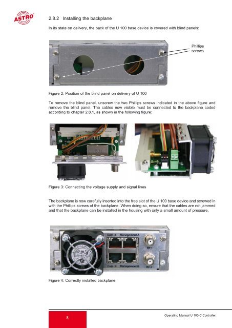
2.8.2 Installing the backplane<br />
In its state on delivery, the back of the U <strong>100</strong> base device is covered with blind panels:<br />
Figure 2: Position of the blind panel on delivery of U <strong>100</strong><br />
To remove the blind panel, unscrew the two Phillips screws indicated in the above figure and<br />
remove the blind panel. The cables now visible must be connected to the backplane coded<br />
according to chapter 2.8.1, as shown in the following figure:<br />
Figure 3: Connecting the voltage supply and signal lines<br />
The backplane is now carefully inserted into the free slot of the U <strong>100</strong> base device and screwed in<br />
with the Phillips screws of the backplane. When doing so, ensure that the cables are not jammed<br />
and that the backplane can be installed in the housing with only a small amount of pressure.<br />
Figure 4: Correctly installed backplane<br />
8<br />
Phillips<br />
screws<br />
Operating Manual U <strong>100</strong>-C Controller