U 100-C - Astro
U 100-C - Astro
U 100-C - Astro

You also want an ePaper? Increase the reach of your titles
YUMPU automatically turns print PDFs into web optimized ePapers that Google loves.
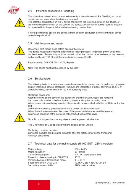
2.4 Potential equalisation / earthing<br />
The subscriber network must be earthed correctly in accordance with EN 50083-1, and must<br />
remain earthed even when the device is removed.<br />
The potential equalisation on the U <strong>100</strong> is effected via the fastening plates of the device, or<br />
via the earthing connection on the back of the device. Devices within hand's reached must be<br />
incorporated into the potential equalisation among one another.<br />
It is not permitted to operate the device without an earth conductor, device earthing or device<br />
potential equalisation!<br />
2.5 Maintenance and repair<br />
Disconnect both mains plugs before opening the device!<br />
The device must not be opened other than for repair purposes. In general, power units must<br />
not be opened. Repairs may only be carried out at the plant or at workshops, or by persons,<br />
authorised by ASTRO Strobel Kommunikationssysteme GmbH.<br />
Read carefully: DIN VDE 0701- 0702, Repairs<br />
Note: The device must not be opened by the user!<br />
2.6 Service tasks<br />
The following tasks, in which screw connections have to be opened, can be performed by appropriately<br />
instructed service personnel: Removal and installation of signal converters (e.g. U 114)<br />
and power units, also when the U <strong>100</strong> is in operating mode.<br />
Replacing power units<br />
After the screws on the cover of the power unit chamber (ASTRO logo) are removed,<br />
the power units can be pulled out by hand, forwards along the mounting panel.<br />
When power units are being installed, there should be no contact with the ventilator or the fan<br />
grid,<br />
and only the mounting panel attached to the power unit should be used.<br />
When the tasks are complete, the cover of the power unit chamber must be replaced;<br />
continuous operation of the device is not permitted without this cover.<br />
Note: Do not put your hand or any objects into the power unit chamber.<br />
The U <strong>100</strong> must only be operated with the original power unit(s)!<br />
Replacing converter modules:<br />
Converter modules can be pulled outwards after the safety screw on the front panel<br />
has been unscrewed.<br />
2.7 Technical data for the mains supply (U <strong>100</strong> SNT - 230 V version)<br />
Mains voltage: <strong>100</strong> – 240 V<br />
Mains frequency: 50 / 60 Hz<br />
Current consumption: 1.4 – 0.7 A per power unit<br />
Protection class according to EN 60529: IP 20<br />
Permitted ambient temperature range: 0 … 45 °C<br />
Secondary fuse in U<strong>100</strong>-230: T3,15A L 250 V IEC 60127-2/3<br />
Secondary fuses in U114: SMD, various values<br />
6<br />
Operating Manual U <strong>100</strong>-C Controller