
Create successful ePaper yourself
Turn your PDF publications into a flip-book with our unique Google optimized e-Paper software.
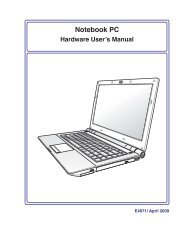
Notebook PC<br />
Hardware User’s <strong>Manual</strong><br />
E4128 / Aug 2008
2<br />
Contents<br />
Table of Contents<br />
1. Introducing the Notebook PC<br />
About This User’s <strong>Manual</strong> 6<br />
Notes For This <strong>Manual</strong> 6<br />
Preparing your Notebook PC9<br />
2. Knowing the Parts<br />
Top Side12<br />
Bottom Side 14<br />
Rear Side16<br />
Right Side 18<br />
Left Side 19<br />
Front Side 20<br />
3. Getting Started<br />
Power System 22<br />
Using AC Power 22<br />
Using Battery Power 23<br />
Battery Care 23<br />
Powering ON the Notebook PC 24<br />
The Power-On Self Test (POST) 24<br />
Checking Battery Power 25<br />
Charging the Battery Pack 25<br />
Power Options 26<br />
Power Management Modes 27<br />
Sleep and Hibernate 27<br />
Thermal Power Control 27<br />
Special Keyboard Functions 28<br />
Colored Hot Keys 28<br />
Microsoft Windows Keys 30<br />
Keyboard as a Numeric Keypad 30<br />
Keyboard as Cursors 30<br />
Switches and Status Indicators 31<br />
Switches31<br />
Status Indicators 32
Table of Contents (Cont.)<br />
4. Using the Notebook PC<br />
Contents<br />
Pointing Device36<br />
Using the Touchpad 36<br />
Touchpad Usage Illustrations 37<br />
Caring for the Touchpad 38<br />
Automatic Touchpad Disabling 38<br />
Storage Devices 39<br />
Inserting an Expansion Card 39<br />
Removing an Expansion Card 39<br />
Optical Drive 40<br />
Flash Memory Card Reader 42<br />
Hard Disk Drive 43<br />
Memory (RAM)44<br />
Connections45<br />
Modem Connection (on selected models) 45<br />
Network Connection 46<br />
Wireless LAN Connection (on selected models) 47<br />
Windows Wireless Network Connection 48<br />
Bluetooth Wireless Connection (on selected models) 49<br />
Appendix<br />
Optional Accessories A-2<br />
Optional Connections A-3<br />
Bluetooth Mouse Setup (optional) A-4<br />
Operating System and Software A-6<br />
System BIOS Settings A-7<br />
Common Problems and Solutions A-9<br />
Windows Vista Software Recovery A-15<br />
Glossary A-17<br />
Declarations and Safety Statements A-21<br />
Notebook PC Information A-32<br />
3
4<br />
Contents
1. Introducing the Notebook PC<br />
About This User’s <strong>Manual</strong><br />
Notes For This <strong>Manual</strong><br />
Safety Precautions<br />
Preparing your Notebook PC<br />
There may be differences between your Notebook PC and the drawings shown in this<br />
manual. Please accept your Notebook PC as being correct.<br />
Photos and icons in this manual are used for artistic purposes only and do not show<br />
what is actually used in the product itself.
[ ]<br />
1 Introducing the Notebook PC<br />
About This User’s <strong>Manual</strong><br />
You are reading the Notebook PC User’s <strong>Manual</strong>. This User’s <strong>Manual</strong> provides information<br />
on the various components in the Notebook PC and how to use them. The following<br />
are major sections of this User’s <strong>Manual</strong>s:<br />
1. Introducing the Notebook PC<br />
Introduces you to the Notebook PC and this User’s <strong>Manual</strong>.<br />
2. Knowing the Parts<br />
Gives you information on the Notebook PC’s components.<br />
3. Getting Started<br />
Gives you information on getting started with the Notebook PC.<br />
4. Using the Notebook PC<br />
Gives you information on using the Notebook PC’s components.<br />
5. Appendix<br />
Introduces you to optional accessories and gives additional information.<br />
Notes For This <strong>Manual</strong><br />
A few notes and warnings in bold are used throughout this guide that you should be aware of in order<br />
to complete certain tasks safely and completely. These notes have different degrees of importance as<br />
described below:<br />
NOTE: Tips and information for special situations.<br />
TIP: Tips and useful information for completing tasks.<br />
IMPORTANT! Vital information that must be followed to prevent damage to data, components,<br />
or persons.<br />
WARNING! Important information that must be followed for safe operation.<br />
Text enclosed in < > or [ ] represents a key on the keyboard; do not actually type the<br />
< > or [ ] and the enclosed letters.
Introducing the Notebook PC 1<br />
Safety Precautions<br />
The following safety precautions will increase the life of the Notebook PC. Follow all precautions and<br />
instructions. Except as described in this manual, refer all servicing to qualified personnel. Do not use<br />
damaged power cords, accessories, or other peripherals. Do not use strong solvents such as thinners,<br />
benzene, or other chemicals on or near the surface.<br />
IMPORTANT! Disconnect the AC power and remove the battery pack(s) before cleaning.<br />
Wipe the Notebook PC using a clean cellulose sponge or chamois cloth dampened<br />
with a solution of nonabrasive detergent and a few drops of warm water and remove<br />
any extra moisture with a dry cloth.<br />
DO NOT place on uneven or unstable<br />
work surfaces. Seek servicing if the<br />
casing has been damaged.<br />
DO NOT press or touch the display<br />
panel. Do not place together with<br />
small items that may scratch or enter<br />
the Notebook PC.<br />
DO NOT expose to dirty or dusty environments.<br />
DO NOT operate during<br />
a gas leak.<br />
DO NOT leave the Notebook PC on<br />
your lap or any part of the body in<br />
order to prevent discomfort or injury<br />
from heat exposure.<br />
SAFE TEMP: This Notebook PC<br />
should only be used in environments<br />
with ambient temperatures between<br />
5°C (41°F) and 35°C (95°F)<br />
DO NOT place or drop objects on top<br />
and do not shove any foreign objects<br />
into the Notebook PC.<br />
DO NOT expose to strong magnetic<br />
or electrical fields.<br />
DO NOT expose to or use near liquids,<br />
rain, or moisture. DO NOT use the<br />
modem during an electrical storm.<br />
Battery safety warning:<br />
DO NOT throw the battery in fire.<br />
DO NOT short circuit the contacts.<br />
DO NOT disassemble the battery.<br />
INPUT RATING: Refer to the rating<br />
label on the bottom of the Notebook<br />
PC and be sure that your power adapter<br />
complies with the rating.<br />
DO NOT carry or cover a Notebook PC that is powered ON with any materials that will<br />
reduce air circulation such as a carrying bag.<br />
DO NOT throw the Notebook PC in municipal waste. This product has been designed<br />
to enable proper reuse of parts and recycling. The symbol of the crossed out wheeled bin<br />
indicates that the product (electrical, electronic equipment and mercury-containing button<br />
cell battery) should not be placed in municipal waste. Check local regulations for disposal<br />
of electronic products.
8<br />
1 Introducing the Notebook PC<br />
Transportation Precautions<br />
To prepare the Notebook PC for transport, you should turn it OFF and disconnect all external peripherals<br />
to prevent damage to the connectors. The hard disk drive’s head retracts when the power is turned<br />
OFF to prevent scratching of the hard disk surface during transport. Therefore, you should not transport<br />
the Notebook PC while the power is still ON. Close the display panel and check that it is latched securely<br />
in the closed position to protect the keyboard and display panel.<br />
CAUTION! The Notebook PC’s surface is easily dulled if not properly cared for. Be<br />
careful not to rub or scrape the Notebook PC surfaces.<br />
Cover Your Notebook PC<br />
Purchase a carrying bag to protect the Notebook PC from dirt, water, shock, and scratches.<br />
Charge Your Batteries<br />
If you intend to use battery power, be sure to fully charge your battery pack and any optional battery<br />
packs before going on long trips. Remember that the power adapter charges the battery pack as long as<br />
it is plugged into the computer and an AC power source. Be aware that it takes much longer to charge<br />
the battery pack when the Notebook PC is in use.<br />
Airplane Precautions<br />
Contact your airline if you want to use the Notebook PC on the airplane. Most airlines will have restrictions<br />
for using electronic devices. Most airlines will allow electronic use only between and not during<br />
takeoffs and landings.<br />
CAUTION! There are three main types of airport security devices: X-ray machines<br />
(used on items placed on conveyor belts), magnetic detectors (used on people walking<br />
through security checks), and magnetic wands (hand-held devices used on people or<br />
individual items). You can send your Notebook PC and diskettes through airport X-ray<br />
machines. However, it is recommended that you do not send your Notebook PC or<br />
diskettes through airport magnetic detectors or expose them to magnetic wands.
Introducing the Notebook PC 1<br />
Preparing your Notebook PC<br />
These are only quick instructions for using your Notebook PC. Read the later pages for detailed information<br />
on using your Notebook PC.<br />
1. Install the battery pack 2. Connect the AC Power Adapter<br />
3. Open the Display Panel 4. Turn ON the Notebook PC<br />
IMPORTANT! When opening, do not<br />
force the display panel down to the table<br />
or else the hinges may break! Never lift<br />
the Notebook PC by the display panel!<br />
The power switch turns ON and OFF the Notebook<br />
PC or putting the Notebook PC into sleep or hibernation<br />
modes. Actual behavior of the power switch<br />
can be customized in Windows Control Panel ><br />
Power Options > System Settings.
10<br />
1 Introducing the Notebook PC
2. Knowing the Parts<br />
Basic sides of the Notebook PC<br />
There may be differences between your Notebook PC and the drawings shown in this<br />
manual. Please accept your Notebook PC as being correct.<br />
Photos and icons in this manual are used for artistic purposes only and do not show<br />
what is actually used in the product itself.<br />
11
12<br />
2 Knowing the Parts<br />
Top Side<br />
Refer to the diagram below to identify the components on this side of the Notebook PC.<br />
The keyboard differs for each territory.<br />
1<br />
(Instant keys vary by model)<br />
2<br />
3<br />
4<br />
5
1<br />
2<br />
3<br />
4<br />
5<br />
Knowing the Parts 2<br />
Display Panel<br />
The display panel functions the same as a desktop CRT monitor. The Notebook PC uses an active<br />
matrix TFT LCD, which provides excellent viewing like that of desktop monitors. Unlike desktop<br />
CRT monitors, the LCD panel does not produce any radiation or flickering, so it is easier on the eyes.<br />
Use a soft cloth without chemical liquids (use plain water if necessary) to clean the display panel.<br />
Instant Keys<br />
Instant keys allow you to launch frequently used applications with one push of a button.<br />
Details are described in section 3.<br />
Keyboard<br />
The keyboard provides full-sized keys with comfortable travel (depth at which the keys<br />
can be depressed) and palm rest for both hands. Two Windows function keys are provided<br />
to help ease navigation in the Windows operating system.<br />
Touchpad and Buttons<br />
The touchpad with its buttons is a pointing device that provides the same functions as a<br />
desktop mouse. A software-controlled scrolling function is available after setting up the<br />
included touchpad utility to allow easy Windows or web navigation.<br />
Status Indicators (front)<br />
Status indicators represent various hardware/software conditions. See indicator details in section 3.<br />
13
14<br />
2 Knowing the Parts<br />
Bottom Side<br />
Refer to the diagram below to identify the components on this side of the Notebook PC.<br />
The bottom side may vary in appearance depending on model.<br />
The battery pack size varies depending on model.<br />
6<br />
5<br />
4<br />
4 3<br />
1<br />
2<br />
3<br />
1<br />
2
1<br />
2<br />
3<br />
4<br />
5<br />
Knowing the Parts 2<br />
WARNING! The bottom of the Notebook PC can get very hot. Be careful when handling<br />
the Notebook PC while it is in operation or recently been in operation. High temperatures<br />
are normal during charging or operation. Do not use on soft surfaces such as<br />
beds or sofas which may block the vents. DO NOT PUT THE NOTEBOOK PC ON YOUR<br />
LAP OR OTHER PARTS OF THE BODY TO AVOID INJURY FROM THE HEAT.<br />
Central Processor Unit (CPU) Compartment<br />
Some Notebook PC models feature a socketed-processor design to allow upgrading to faster<br />
processors in the future. Some models feature a ULV design for compactness and may not<br />
be upgraded. Visit an authorized service center or retailer for information on upgrades.<br />
WARNING! End-user removal of the CPU or hard disk drive will void the warranty.<br />
Memory (RAM) Compartment<br />
The memory compartment provides expansion capabilities for additional memory. Additional<br />
memory will increase application performance by decreasing hard disk access. The BIOS<br />
automatically detects the amount of memory in the system and configures CMOS accordingly<br />
during the POST (Power-On-Self-Test) process. There is no hardware or software (including<br />
BIOS) setup required after the memory is installed. Visit an authorized service center or retailer for information<br />
on memory upgrades for your Notebook PC. Only purchase expansion modules from authorized retailers of this<br />
Notebook PC to ensure maximum compatibility and reliability.<br />
Hard Disk Drive Compartment<br />
The hard disk drive is secured in a compartment. Visit an authorized service center or retailer for<br />
information on hard disk drive upgrades for your Notebook PC. Only purchase hard disk drives<br />
from authorized retailers of this Notebook PC to ensure maximum compatibility and reliability.<br />
Battery Pack<br />
The battery pack is automatically charged when the Notebook PC is connected to an AC power source<br />
and maintains power to the Notebook PC when AC power is not connected. This allows use when moving<br />
temporarily between locations. Battery time varies by usage and by the specifications for this Notebook<br />
PC. The battery pack cannot be disassembled and must be purchased as a single unit.<br />
Shutdown Button (Emergency) (on selected models)<br />
In case your operating system cannot properly turn OFF or restart, the shutdown button can<br />
be pressed with a straightened paper clip to shutdown the Notebook PC.<br />
6 Wireless LAN (WLAN) Compartment (on selected models)<br />
The WLAN compartment allows the installation of a wireless networking card in order to<br />
wirelessly connect to network access points or other wireless networking devices.<br />
1
1<br />
2<br />
3<br />
4<br />
1<br />
2.0<br />
2 Knowing the Parts<br />
Rear Side<br />
Refer to the diagram below to identify the components on this side of the Notebook PC.<br />
1 2 3 4 5 6 7<br />
3 1<br />
4 5 6 7<br />
Display (Monitor) Output<br />
The 15-pin D-sub monitor port supports a standard VGA-compatible device such as a monitor<br />
or projector to allow viewing on a larger external display.<br />
Serial Port (on selected models)<br />
The 9-pin D-sub serial port supports native serial devices such as a serial drawing<br />
tablets, serial mouse, or serial modem. Serial devices have been slowly replaced by<br />
USB devices.<br />
USB Port (2.0/1.1)<br />
The USB (Universal Serial Bus) port is compatible with USB 2.0 or USB 1.1 devices such<br />
as keyboards, pointing devices, cameras, hard disk drives, printers, and scanners connected in<br />
a series up to 12Mbits/sec (USB 1.1) and 480Mbits/sec (USB 2.0). USB allows many devices<br />
to run simultaneously on a single computer, with some peripherals acting as additional plug-in sites or<br />
hubs. USB supports hot-swapping of devices so that most peripherals can be connected or disconnected<br />
without restarting the computer.<br />
LAN Port<br />
The RJ-45 LAN port with eight pins is larger than the RJ-11 modem port and supports a<br />
standard Ethernet cable for connection to a local network. The built-in connector allows<br />
convenient use without additional adapters.<br />
8<br />
8
5<br />
6<br />
7<br />
8<br />
Knowing the Parts 2<br />
Modem Port (on selected models)<br />
The RJ-11 modem port with two pins is smaller than the RJ-45 LAN port and supports<br />
a standard telephone cable. The internal modem supports up to 56K V.90 transfers. The<br />
built-in connector allows convenient use without additional adapters.<br />
IMPORTANT! The built-in modem does not support the voltage used in digital<br />
phone systems. Do not connect the modem port to a digital phone system or<br />
else damage will occur to the Notebook PC.<br />
Power (DC) Input<br />
The supplied power adapter converts AC power to DC power for use with this jack. Power supplied<br />
through this jack supplies power to the Notebook PC and charges the internal battery pack.<br />
To prevent damage to the Notebook PC and battery pack, always use the supplied power<br />
adapter. CAUTION: MAY BECOME WARM TO HOT WHEN IN USE. BE SURE<br />
NOT TO COVER THE ADAPTER AND KEEP IT AWAY FROM YOUR BODY.<br />
Kensington ® Lock Port<br />
The Kensington ® lock port allows the Notebook PC to be secured using Kensington ® compatible<br />
Notebook PC security products. These security products usually include a metal<br />
cable and lock that prevent the Notebook PC to be removed from a fixed object.<br />
Some may also include a motion detector to sound an alarm when moved.<br />
Cooling Fan<br />
The cooling fan removes excess heat depending on temperature threshold settings.<br />
IMPORTANT! Make sure that paper, books, clothing, cables, or other objects<br />
do not block any of the air vents or else overheating may occur.<br />
1
1<br />
2<br />
3<br />
4<br />
5<br />
2.0<br />
18<br />
2 Knowing the Parts<br />
Right Side<br />
Refer to the diagram below to identify the components on this side of the Notebook PC.<br />
1 2 3 4 5<br />
Headphone Output Jack<br />
The stereo headphone jack (1/8 inch) is used to connect the Notebook PC’s audio out signal to<br />
amplified speakers or headphones. Using this jack automatically disables the built-in speakers.<br />
Microphone Input Jack<br />
The mono microphone jack (1/8 inch) can be used to connect an external microphone or output<br />
signals from audio devices. Using this jack automatically disables the built-in microphone. Use<br />
this feature for video conferencing, voice narrations, or simple audio recordings.<br />
USB Port (2.0/1.1)<br />
The USB (Universal Serial Bus) port is compatible with USB 2.0 or USB 1.1 devices such<br />
as keyboards, pointing devices, cameras, hard disk drives, printers, and scanners connected in<br />
a series up to 12Mbits/sec (USB 1.1) and 480Mbits/sec (USB 2.0). USB allows many devices<br />
to run simultaneously on a single computer, with some peripherals acting as additional plug-in sites or<br />
hubs. USB supports hot-swapping of devices so that most peripherals can be connected or disconnected<br />
without restarting the computer.<br />
PC Card Slot<br />
One PCMCIA 2.1 compliant PC Card socket is available to support one type I/II PC card. The<br />
socket supports 32-bit CardBus. This allows accommodation of Notebook PC expansion options<br />
such as memory cards, ISDN, SCSI, Smart Cards, and wireless network adapters.<br />
Flash Memory Slot<br />
Normally an external memory card reader must be purchased separately in order to use<br />
memory cards from devices such as digital cameras, MP3 players, mobile phones, and<br />
PDAs. This Notebook PC has a built-in high-speed memory card reader that can conveniently<br />
read from and write to many flash memory cards as mentioned later in this manual.
1<br />
2<br />
3<br />
4<br />
Knowing the Parts 2<br />
Left Side<br />
Refer to the diagram below to identify the components on this side of the Notebook PC.<br />
1 2 3 4<br />
Optical Drive<br />
The Notebook PC comes in various models with different optical drives. The Notebook<br />
PC’s optical drive may support compact discs (CD) and/or digital video discs (DVD) and<br />
may have recordable (R) or re-writable (RW) capabilities. See the marketing specifications<br />
for details on each model.<br />
Optical Drive Activity Indicator (location varies by model)<br />
The optical drive activity indicator shows when data is being transferred by the optical disk drive.<br />
This indicator will light in proportion to the data size transferred.<br />
Optical Drive Electronic Eject<br />
The optical drive eject has an electronic eject button for opening the tray. You can also eject<br />
the optical drive tray through any software player or by right clicking the optical drive in<br />
Windows “Computer” and selecting Eject.<br />
Optical Drive Emergency Eject (location varies by model)<br />
The emergency eject is used to eject the optical drive tray in case the electronic eject does<br />
not work. Do not use the emergency eject in place of the electronic eject.<br />
(continued on next page)<br />
1
1<br />
2<br />
20<br />
2 Knowing the Parts<br />
Front Side<br />
Refer to the diagram below to identify the components on this side of the Notebook PC.<br />
1 2<br />
1<br />
Audio Speakers<br />
The built-in stereo speaker system allows you to hear audio without additional attachments.<br />
The multimedia sound system features an integrated digital audio controller that<br />
produces rich, vibrant sound (results improved with external stereo headphones or speakers).<br />
Audio features are software controlled.<br />
Display Panel Latch<br />
One spring-loaded latch on the front of the Notebook PC locks the display panel in<br />
the closed position when the Notebook PC is not in use. To open the display panel,<br />
negotiate the latch with your thumb and lift up the display panel while holding the<br />
latch. Slowly tilt the display panel forward or backward to a comfortable viewing angle.<br />
WARNING! When opening, do not force the display panel down to the table or else<br />
the hinges may break! Never lift the Notebook PC by the display panel!<br />
4
4<br />
3. Getting Started<br />
Using AC Power<br />
Using Battery Power<br />
Powering ON the Notebook PC<br />
Checking Battery Power<br />
Powering Options<br />
Power Management Modes<br />
Special Keyboard Functions<br />
Switches and Status Indicators<br />
There may be differences between your Notebook PC and the drawings shown in this<br />
manual. Please accept your Notebook PC as being correct.<br />
Photos and icons in this manual are used for artistic purposes only and do not show<br />
what is actually used in the product itself.<br />
21
22<br />
3 Getting Started<br />
Power System<br />
Using AC Power<br />
The Notebook PC power is comprised of two parts,<br />
the power adapter and the battery power system.<br />
The power adapter converts AC power from a wall<br />
outlet to the DC power required by the Notebook<br />
PC. Your Notebook PC comes with a universal<br />
AC-DC adapter. That means that you may connect<br />
the power cord to any 100V-120V as well as 220V-<br />
240V outlets without setting switches or using<br />
power converters. Different countries may require<br />
that an adapter be used to connect the provided<br />
US-standard AC power cord to a different standard.<br />
Most hotels will provide universal outlets to support<br />
different power cords as well as voltages. It is always best to ask an experienced traveler about AC<br />
outlet voltages when bringing power adapters to another country.<br />
You can buy travel kits for the Notebook PC that includes power and modem adapters<br />
for almost every country.<br />
WARNING! DO NOT connect the AC power cord to an AC outlet prior to connecting<br />
the DC plug to the Notebook PC. Doing so may damage the AC-DC adapter.<br />
IMPORTANT! Damage may occur if you use a different adapter to power the Notebook<br />
PC or use the Notebook PC’s adapter to power other electrical devices. If there is<br />
smoke, burning scent, or extreme heat coming from the AC-DC adapter, seek servicing.<br />
Seek servicing if you suspect a faulty AC-DC adapter. You may damage both your<br />
battery pack(s) and the Notebook PC with a faulty AC-DC adapter.<br />
This Notebook PC may come with either a two or three-prong plug depending on territory.<br />
If a three-prong plug is provided, you must use a grounded AC outlet or use a<br />
properly grounded adapter to ensure safe operation of the Notebook PC.<br />
WARNING! THE POWER ADAPTER MAY BECOME WARM TO HOT WHEN IN USE. BE<br />
SURE NOT TO COVER THE ADAPTER AND KEEP IT AWAY FROM YOUR BODY.<br />
Unplug the power adapter or switch off the AC outlet to minimize the power consumption<br />
when the Notebook PC is not in use.
Getting Started 3<br />
Using Battery Power<br />
The Notebook PC is designed to work with a removable battery pack. The battery pack consists of a set<br />
of battery cells housed together. A fully charged pack will provide several hours of battery life, which<br />
can be further extended by using power management features through the BIOS setup. Additional battery<br />
packs are optional and can be purchased separately through a Notebook PC retailer.<br />
Installing and Removing the Battery Pack<br />
Your Notebook PC may or may not have its battery pack installed. If your Notebook PC does not have<br />
its battery pack installed, use the following procedures to install the battery pack.<br />
IMPORTANT! Never attempt to remove the battery pack while the Notebook PC is<br />
turned ON, as this may result in the loss of working data.<br />
To install the battery pack: To remove the battery pack:<br />
IMPORTANT! Only use battery packs and power adapters supplied with this Notebook<br />
PC or specifically approved by the manufacturer or retailer for use with this model or<br />
else damage may occur to the Notebook PC.<br />
Battery Care<br />
The Notebook PC’s battery pack, like all rechargeable batteries, has a limit on the number times it can<br />
be recharged. The battery pack’s useful life will depend on your environment temperature, humidity, and<br />
how your Notebook PC is used. It is ideal that the battery be used in a temperature range between 5˚C<br />
and 35˚C (41˚F and 95˚F). You must also take into account that the Notebook PC’s internal temperature<br />
is higher than the outside temperature. Any temperatures above or below this range will shorten the life<br />
of the battery. But in any case, the battery pack’s usage time will eventually decrease and a new battery<br />
pack must be purchased from an authorized dealer for this Notebook PC. Because batteries also have a<br />
shelf life, it is not recommended to buy extras for storing.<br />
WARNING! For safety reasons, DO NOT throw the battery in fire, DO NOT<br />
short circuit the contacts, and DO NOT disassemble the battery. If there is<br />
any abnormal operation or damage to the battery pack caused by impact,<br />
turn OFF the Notebook PC and contact an authorized service center.<br />
23
24<br />
3 Getting Started<br />
Powering ON the Notebook PC<br />
The Notebook PC’s power-ON message appears on the screen when you turn it ON. If necessary, you<br />
may adjust the brightness by using the hot keys. If you need to run the BIOS Setup to set or modify the<br />
system configuration, press [F2] upon bootup to enter the BIOS Setup. If you press [Tab] during the<br />
splash screen, standard boot information such as the BIOS version can be seen. Press [ESC] and you will<br />
be presented with a boot menu with selections to boot from your available drives.<br />
Before bootup, the display panel flashes when the power is turned ON. This is part of<br />
the Notebook PC’s test routine and is not a problem with the display.<br />
IMPORTANT! To protect the hard disk drive, always wait at least seconds after turning<br />
OFF your Notebook PC before turning it back ON.<br />
WARNING! DO NOT carry or cover a Notebook PC that is powered ON with any materials<br />
that will reduce air circulation such as a carrying bag.<br />
The Power-On Self Test (POST)<br />
When you turn ON the Notebook PC, it will first run through a series of software-controlled diagnostic<br />
tests called the Power-On Self Test (POST). The software that controls the POST is installed as a<br />
permanent part of the Notebook PC’s architecture. The POST includes a record of the Notebook PC’s<br />
hardware configuration, which is used to make a diagnostic check of the system. This record is created<br />
by using the BIOS Setup program. If the POST discovers a difference between the record and the existing<br />
hardware, it will display a message on the screen prompting you to correct the conflict by running<br />
BIOS Setup. In most cases the record should be correct when you receive the Notebook PC. When the<br />
test is finished, you may get a message reporting “No operating system found” if the hard disk was not<br />
preloaded with an operating system. This indicates that the hard disk is correctly detected and ready for<br />
the installation of a new operating system.<br />
Self Monitoring and Reporting Technology<br />
The S.M.A.R.T. (Self Monitoring and Reporting Technology) checks the hard disk<br />
drive during POST and gives a warning message if the hard disk drive requires<br />
servicing. If any critical hard disk drive warning is given during bootup, backup<br />
your data immediately and run Windows disk checking program. To run Window’s<br />
disk checking program: click Start > select Computer > right-click a hard disk<br />
drive icon > choose Properties > click the Tools tab > click Check Now > click<br />
Start. You can also select “Scan ... sectors” for more effective scan and repair but<br />
the process will run slower.<br />
IMPORTANT! If warnings are still given during bootup after running a software disk<br />
checking utility, you should take your Notebook PC in for servicing. Continued use<br />
may result in data loss.
Getting Started 3<br />
Checking Battery Power<br />
The battery system implements the Smart Battery standard under the Windows environment, which<br />
allows the battery to accurately report the amount of charge left in the battery. A fully-charged battery<br />
pack provides the Notebook PC a few hours of working power. But the actual figure varies depending<br />
on how you use the power saving features, your general work habits, the CPU, system memory size,<br />
and the size of the display panel.<br />
Screen captures shown here<br />
are examples only and may<br />
not reflect what you see in<br />
your system.<br />
You will be warned when battery<br />
power is low. If you continue<br />
to ignore the low battery<br />
warnings, the Notebook PC<br />
eventually enters suspend<br />
mode (Windows default uses<br />
STR).<br />
Left-click the battery icon<br />
Right-click the battery icon<br />
Pointer over the battery icon without<br />
power adapter<br />
Pointer over the battery icon with<br />
power adapter<br />
WARNING! Suspend-to-RAM (STR) does not last long when the battery power is<br />
depleted. Suspend-to-Disk (STD) is not the same as power OFF. STD requires a small<br />
amount of power and will fail if no power is available due to complete battery depletion<br />
or no power supply (e.g. removing both the power adapter and battery pack).<br />
Charging the Battery Pack<br />
Before you use your Notebook PC on the road, you will have to charge the battery pack. The battery pack<br />
begins to charge as soon as the Notebook PC is connected to external power using the power adapter.<br />
Fully charge the battery pack before using it for the first time. A new battery pack must completely charge<br />
before the Notebook PC is disconnected from external power. It takes a few hours to fully charge the battery<br />
when the Notebook PC is turned OFF and may take twice the time when the Notebook PC is turned<br />
ON. The battery status indicator on the Notebook PC turns OFF when the battery pack is charged.<br />
The battery starts charging when the charge remaining in the battery drops below %.<br />
This prevents the battery from charging frequently. Minimizing the recharge cycles<br />
helps prolong battery life.<br />
The battery stops charging if the temperature is too high or the battery voltage is too<br />
high.<br />
WARNING! DO NOT leave the battery pack discharged. The battery pack will discharge<br />
over time. If not using a battery pack, it must continued to be charged every three<br />
months to extend recovery capacity or else it may fail to charge in the future.<br />
2
2<br />
3 Getting Started<br />
Power Options<br />
The power switch turns ON and OFF the Notebook PC or putting the Notebook PC into sleep or hibernation<br />
modes. Actual behavior of the power switch can be customized in Windows Control Panel “Power<br />
Options.”<br />
For other options, such as “Switch User, Restart, Sleep, or Shut Down,”<br />
click the arrowhead next to the lock icon.<br />
Restarting or Rebooting<br />
After making changes to your operating system, you may be prompted to<br />
restart the system. Some installation processes will provide a dialog box<br />
to allow restart. To restart the system manually, choose Restart.<br />
IMPORTANT! To protect the hard drive, wait at least seconds after turning OFF your<br />
Notebook PC before turning it back ON.<br />
Emergency Shutdown<br />
In case your operating system cannot properly turn OFF or restart, there are two additional ways to<br />
shutdown your Notebook PC:<br />
(1) Hold the power button over 4 seconds, or (2) Press the shutdown button on the bottom<br />
Use a straightened paper clip to press<br />
the shutdown button.<br />
IMPORTANT! Do not use emergency shutdown while data is being written; doing so<br />
can result in loss or destruction of your data.
Getting Started 3<br />
Power Management Modes<br />
The Notebook PC has a number of automatic or adjustable power saving features that you can use to<br />
maximize battery life and lower Total Cost of Ownership (TCO). You can control some of these features<br />
through the Power menu in the BIOS Setup. ACPI power management settings are made through the<br />
operating system. The power management features are designed to save as much electricity as possible<br />
by putting components into a low power consumption mode as often as possible but also allow full<br />
operation on demand.<br />
Sleep and Hibernate<br />
Power management settings can be found in the Windows > Control Panel<br />
> Power Options. In System Settings, you can define “Sleep/Hibernate”<br />
or “Shut Down” for closing the display panel or pressing the power button.<br />
“Sleep” and “Hibernate” saves power when your Notebook PC is not in<br />
use by turning OFF certain components. When you resume your work,<br />
your last status (such as a document scrolled down half way or email typed<br />
half way) will reappear as if you never left. “Shut Down” will close all<br />
applications and ask if you want to save your work if any are not saved.<br />
Sleep is the same as Suspend-to-RAM (STR). This function stores your<br />
current data and status in RAM while many components are turned OFF.<br />
Because RAM is volatile, it requires power to keep (refresh) the data.<br />
Click the Start button and the arrowhead next to the lock icon to see this<br />
option. You can also use the keyboard shortcut [Fn F1] to activate this<br />
mode. Recover by pressing any keyboard key except [Fn]. (NOTE: The<br />
power indicator will blink in this mode.)<br />
Hibernate is the same as Suspend-to-Disk (STD) and stores your current data and status on the hard<br />
disk drive. By doing this, RAM does not have to be periodically refreshed and power consumption is<br />
greatly reduced but not completely eliminated because certain wake-up components like LAN needs to<br />
remain powered. “Hibernate” saves more power compared to “Sleep”. Click the Start button and the<br />
arrowhead next to the lock icon to see this option. Recover by pressing the power button. (NOTE: The<br />
power indicator will be OFF in this mode.)<br />
Thermal Power Control<br />
There are three power control methods for controlling the Notebook PC’s thermal state. These power<br />
control cannot be configured by the user and should be known in case the Notebook PC should enter<br />
these states. The following temperatures represent the chassis temperature (not CPU).<br />
• The fan turns ON for active cooling when the temperature reaches the safe upper limit.<br />
• The CPU decreases speed for passive cooling when the temperature exceeds the safe upper limit.<br />
• The system shut down for critical cooling when temperature exceeds the maximum safe upper<br />
limit.<br />
2
28<br />
3 Getting Started<br />
Special Keyboard Functions<br />
Colored Hot Keys<br />
The following defines the colored hot keys on the Notebook PC’s keyboard. The<br />
colored commands can only be accessed by first pressing and holding the function<br />
key while pressing a key with a colored command.<br />
The Hot Key locations on the function keys may vary depending on model but the<br />
functions should remain the same. Follow the icons instead of the function keys.<br />
“Zz” Icon (F1): Places the Notebook PC in suspend mode (either Save-to-RAM or Saveto-Disk<br />
depending on sleep button setting in power management setup).<br />
Radio Tower (F2): Wireless Models Only: Toggles the<br />
internal wireless LAN or Bluetooth (on selected models)<br />
ON or OFF with an on-screen-display. When enabled, the<br />
corresponding wireless indicator will light. Windows software settings are necessary to<br />
use the wireless LAN or Bluetooth.<br />
Envelope Icon (F3): Pressing this button will launch your Email application while<br />
Windows is running.<br />
“e” Icon (F4): Pressing this button will launch your Internet browser application<br />
while Windows is running.<br />
Filled Sun Icon (F5):<br />
Decreases the display brightness<br />
Open Sun Icon (F6):<br />
Increases the display brightness<br />
LCD Icon (F7): Toggles the display panel ON and OFF. (On certain models; stretches<br />
the screen area to fill the entire display when using low resolution modes.)<br />
LCD/Monitor Icons (F8): Toggles between the Notebook PC’s LCD display and<br />
an external monitor in this series: Notebook PC LCD -> External Monitor -> Both.<br />
(This function does not work in 256 Colors, select High Color in Display Property<br />
Settings.) NOTE: Must connect an external monitor “before” booting up.<br />
Crossed-out Touchpad (F9): Toggles the built-in touchpad LOCKED (disabled)<br />
and UNLOCKED (enabled). Locking the touchpad will prevent you from accidentally<br />
moving the cursor while typing and is best used with an external<br />
pointing device such as a mouse.
Colored Hot Keys (cont.)<br />
Speaker Icons (F10):<br />
Toggles the speakers ON and OFF (only in Windows OS)<br />
Speaker Down Icon (F11):<br />
Decreases the speaker volume (only in Windows OS)<br />
Speaker Up Icon (F12):<br />
Increases the speaker volume (only in Windows OS)<br />
Getting Started 3<br />
Num Lk (Ins): Toggles the numeric keypad (number lock) ON and OFF. Allows you<br />
to use a larger portion of the keyboard for number entering.<br />
Scr Lk (Del): Toggles the “Scroll Lock” ON and OFF. Allows you to use a larger<br />
portion of the keyboard for cell navigation.<br />
Fn+C: Toggles “Splendid Video Intelligent Technology”<br />
function ON and OFF. This allows switching<br />
between different display color enhancement modes<br />
in order to improve contrast, brightness, skin tone, and color saturation for red, green, and<br />
blue independently. You can see the current mode through the on-screen display (OSD).<br />
Power4Gear eXtreme (Fn+Space Bar): This key<br />
toggles power savings between various power saving<br />
modes. The power saving modes control many<br />
aspects of the Notebook PC to maximize performance versus battery time. Applying or<br />
removing the power adapter will automatically switch the system between AC mode and<br />
battery mode. You can see the current mode through the on-screen display (OSD).<br />
2
30<br />
3 Getting Started<br />
Microsoft Windows Keys<br />
There are two special Windows keys on the keyboard as described below.<br />
The key with the Windows Logo activates the Start menu located at the bottom left of the Windows<br />
desktop.<br />
The other key, that looks like a Windows menu with a small cursor, activates the properties menu<br />
and is equivalent to pressing the right mouse button on a Windows object.<br />
Keyboard as a Numeric Keypad<br />
The numeric keypad is embedded in the keyboard and consists<br />
of 15 keys that make number intensive input more convenient.<br />
These dual-purpose keys are labeled in orange on the key caps.<br />
Numeric assignments are located at the upper right hand corner<br />
of each key as shown in the figure. When the numeric keypad is<br />
engaged by pressing [Fn][Ins/Num LK], the number lock LED lights<br />
up. If an external keyboard is connected, pressing the [Ins/Num LK]<br />
on the external keyboard enables/disables the NumLock on both keyboards<br />
simultaneously. To disable the numeric keypad while keeping<br />
the keypad on an external keyboard activated, press the [Fn][Ins/Num LK] keys on the Notebook PC.<br />
Keyboard as Cursors<br />
The keyboard can be used as cursors while Number Lock is<br />
ON or OFF in order to increase navigation ease while entering<br />
numeric data in spreadsheets or similar applications.<br />
With Number Lock OFF, press [Fn] and one of the cursor keys<br />
shown below. For example [Fn][8] for up, [Fn][K] for down,<br />
[Fn][U] for left, and [Fn][O] for right.<br />
With Number Lock ON, use [Shift] and one of the cursor keys shown<br />
below. For example [Shift][8] for up, [Shift][K] for down, [Shift][U]<br />
for left, and [Shift][O] for right.<br />
The red arrows are illustrated here for your reference. They are not labeled on the<br />
keyboard as shown here.
Switches and Status Indicators<br />
Switches<br />
Getting Started 3<br />
Power Switch<br />
The power switch turns ON and OFF the Notebook PC or putting the Notebook PC into sleep<br />
or hibernation modes. Actual behavior of the power switch can be customized in Windows<br />
Control Panel “Power Options.”<br />
Power4Gear eXtreme Key (on selected models)<br />
The Power4Gear eXtreme key toggles power savings between<br />
various power saving modes. The power saving modes control<br />
many aspects of the Notebook PC to maximize performance versus<br />
battery time. Applying or removing the power adapter will automatically switch the system between<br />
AC mode and battery mode. The selected mode is shown on the display.<br />
Express Gate Key (on selected models)<br />
Pressing this button will launch Express Gate. Refer to the Express Gate User’s <strong>Manual</strong> for details.<br />
Wireless Switch (on selected models)<br />
Wireless Models Only: Toggles the internal wireless LAN or Bluetooth (on selected models)<br />
ON or OFF with an on-screen display. When enabled, the corresponding wireless indicator<br />
will light. Windows software settings are necessary to use the wireless LAN or Bluetooth.<br />
Touchpad Lock Key (on selected models)<br />
Pressing this button will lock (disable) the built-in touchpad. Locking the touchpad will prevent you from<br />
accidentally moving the pointer while typing and is best used with an external mouse (pointing device).<br />
To unlock (enable) the touchpad, simply press this button again.<br />
31
32<br />
3 Getting Started<br />
Switches and Status Indicators (cont.)<br />
Status Indicators<br />
Front<br />
Sleep Indicator<br />
The sleep indicator blinks when the Notebook PC is in the Suspend-to-RAM (Sleep) mode. This<br />
indicator is OFF when the Notebook PC is turned OFF or in the Suspend-to-Disk (Hibernation)<br />
mode.<br />
Battery Charge Indicator<br />
The battery charge indicator is an LED that shows the status of the battery’s power as follows:<br />
ON: The Notebook PC’s battery is charging when AC power is connected.<br />
OFF: The Notebook PC’s battery is charged or completely drained.<br />
Blinking: Battery power is less than 10% and the AC power is not connected.<br />
Drive Activity Indicator<br />
Indicates that the Notebook PC is accessing one or more storage device(s) such as the hard<br />
disk. The light flashes proportional to the access time.<br />
Wireless Indicator (on selected models)<br />
This is only applicable on models with built-in wireless LAN and/or built-in Bluetooth.<br />
When the built-in wireless LAN and/or built-in Bluetooth is enabled, this indicator will<br />
light. (Windows software settings are necessary.)
Switches and Status Indicators (cont.)<br />
Status Indicators (cont.)<br />
Top<br />
Number Lock Indicator<br />
Indicates that number lock [Num Lk] is activated when lighted. Number lock allows some<br />
of the keyboard letters to act as numbers for easier numeric data input.<br />
Capital Lock Indicator<br />
Indicates that capital lock [Caps Lock] is activated when lighted. Capital lock allows some<br />
of the keyboard letters to type using capitalized letters (e.g. A, B, C). When the capital<br />
lock light is OFF, the typed letters will be in the lower case form (e.g. a,b,c).<br />
Getting Started 3<br />
33
34<br />
3 Getting Started
4. Using the Notebook PC<br />
Pointing Device<br />
Storage Devices<br />
Expansion Card<br />
Optical drive<br />
Flash memory card reader<br />
Hard disk drive<br />
Memory (RAM)<br />
Connections<br />
Modem Connection (on selected models)<br />
Network Connection<br />
Wireless LAN Connection (on selected models)<br />
Bluetooth Wireless Connection (on selected models)<br />
There may be differences between your Notebook PC and the drawings shown in this<br />
manual. Please accept your Notebook PC as being correct.<br />
Photos and icons in this manual are used for artistic purposes only and do not show<br />
what is actually used in the product itself.<br />
3
3<br />
4 Using the Notebook PC<br />
Pointing Device<br />
The Notebook PC’s integrated touchpad pointing<br />
device is fully compatible with all two/three-button<br />
and scrolling knob PS/2 mice. The touchpad is<br />
pressure sensitive and contains no moving parts;<br />
therefore, mechanical failures can be avoided. A<br />
device driver is still required for working with some<br />
application software.<br />
IMPORTANT! Do not use any objects in<br />
place of your finger to operate the touchpad<br />
or else damage may occur to the<br />
touchpad’s surface.<br />
Using the Touchpad<br />
Light pressure with the tip of your finger is all that is<br />
required to operate the touchpad. Because the touchpad<br />
is electrostatic sensitive, objects cannot be used in<br />
place of your fingers. The touchpad’s primary function<br />
is to move the cursor around or select items displayed<br />
on the screen with the use of your fingertip instead of<br />
a standard desktop mouse. The following illustrations<br />
demonstrate proper use of the touchpad.<br />
Moving The Pointer<br />
Place your finger in the center of the touchpad and<br />
slide in a direction to move the pointer.<br />
Scrolling (on selected models)<br />
Slide your finger up or down on the right side to<br />
scroll a window up or down.<br />
A software-controlled scrolling function<br />
is available after setting up the<br />
included touchpad utility to allow easy<br />
Windows or web navigation.<br />
Slide finger<br />
left<br />
Scroll Up<br />
Scroll Down<br />
Slide finger<br />
forward<br />
Slide finger<br />
backward<br />
Pointer<br />
Movement<br />
Scroll<br />
Left Click<br />
Right Click<br />
Slide finger<br />
right
Touchpad Usage Illustrations<br />
Using the Notebook PC 4<br />
Clicking/Tapping - With the cursor over an item, press the left button or use your fingertip to touch the<br />
touchpad lightly, keeping your finger on the touchpad until the item is selected. The selected item will<br />
change color. The following 2 examples produce the same results.<br />
Clicking Tapping<br />
Press the left cursor button and<br />
release.<br />
Double-clicking/Double-tapping - This is a common skill for launching a program directly from the<br />
corresponding icon you select. Move the cursor over the icon you wish to execute, press the left button or<br />
tap the pad twice in rapid succession, and the system launches the corresponding program. If the interval<br />
between the clicks or taps is too long, the operation will not be executed. You can set the double-click speed<br />
using the Windows Control Panel “Mouse.” The following 2 examples produce the same results.<br />
Double-<br />
Clicking<br />
Press the left button twice and<br />
release.<br />
Double-<br />
Tapping<br />
Lightly but rapidly strike the<br />
touchpad.<br />
Lightly but rapidly strike the<br />
touchpad twice.<br />
Dragging - Dragging means to pick up an item and place it anywhere on the screen you wish. You can<br />
move the cursor over the item you select, and while keeping the left button depressed, moving the cursor<br />
to the desired location, then release the button. Or, you can simply double-tap on the item and hold while<br />
dragging the item with your fingertip. The following illustrations produce the same results.<br />
Dragging-<br />
Clicking<br />
Hold left button and slide finger<br />
on touchpad.<br />
Dragging-<br />
Tapping<br />
Lightly strike the touchpad twice,<br />
sliding finger on touchpad during<br />
second strike.<br />
3
Mouse Properties > Device Settings.<br />
Find Mouse properties in the “Control Panel”<br />
Models with Synaptics touchpad<br />
Models with ALPS touchpad<br />
Select this option to<br />
enable this feature<br />
Select this option to<br />
enable this feature
Using the Notebook PC 4<br />
Storage Devices<br />
Storage devices allow the Notebook PC to read or write documents, pictures, and other files to various<br />
data storage devices. This Notebook PC has the following storage devices:<br />
• Expansion card<br />
• Optical drive<br />
• Flash memory reader<br />
• Hard disk drive<br />
Inserting an Expansion Card<br />
Be sure the card is<br />
level when inserting<br />
1. If there is a plastic protector in the slot, remove<br />
it using the removing instructions below.<br />
2. Insert the card with the connector side first and<br />
label side up. Standard cards will be flush with<br />
the Notebook PC when fully inserted.<br />
Removing an Expansion Card<br />
To remove the card, first remove all cables or adapters attached to the card, then double-click the Safely<br />
Remove Hardware icon on the Windows taskbar and stop the card before removing.<br />
1<br />
1. Press in the toggle eject button and release. The<br />
recessed spring loaded toggle button will extend<br />
when pushed in and released.<br />
2<br />
3. Carefully connect any cables or adapters needed<br />
by the card. Usually connectors can only be<br />
inserted in one orientation. Look for a sticker,<br />
icon, or marking on one side of the connector<br />
representing the top side.<br />
2. Press the extended button again to eject the<br />
card. Carefully pull the ejected card out of the<br />
socket.<br />
3
40<br />
4 Using the Notebook PC<br />
Optical Drive<br />
Inserting an optical disc<br />
1. While the Notebook PC’s power is ON, press<br />
the drive’s eject button and the tray will eject<br />
out partially.<br />
3. Hold the disc by the edge and face the disc’s<br />
printed side up. Push down on both sides of<br />
the disc’s center until the disc snaps onto the<br />
hub. The hub should be higher than the<br />
disc when correctly mounted.<br />
2. Gently pull on the drive’s front panel and slide<br />
the tray completely out. Be careful not to touch<br />
the CD drive lens and other mechanisms. Make<br />
sure there are no obstructions that may get<br />
jammed under the drive’s tray.<br />
4. Slowly push the drive’s tray back in. The drive<br />
will begin reading the table of contents (TOC)<br />
on the disc. When the drive stops, the disc is<br />
ready to be used.<br />
It is normal to hear as well as feel the CD spinning with great intensity in the CD drive<br />
while data is read.
Optical Drive (Cont.)<br />
Removing an optical disc<br />
Eject the tray and gently pry the edge of the disc<br />
upwards at an angle to remove the disc from<br />
the hub.<br />
Using the Notebook PC 4<br />
Emergency eject<br />
Actual location will<br />
vary by model<br />
The emergency eject is located in a hole on the optical<br />
drive and is used to eject the optical drive tray<br />
in case the electronic eject does not work. Do not<br />
use the emergency eject in place of the electronic<br />
eject. Note: Make sure not to stab the activity<br />
indicator located in the same area.<br />
Using the Optical Drive<br />
Optical discs and equipment must be handled with care because of the precise mechanics involved.<br />
Keep in mind the important safety instructions from your CD suppliers. Unlike desktop optical drives,<br />
the Notebook PC uses a hub to hold the CD in place regardless of the angle. When inserting a CD, it is<br />
important that the CD be pressed onto the center hub or else the optical drive tray will scratch the CD.<br />
WARNING! If the CD disc is not properly locked onto the center hub, the CD can be<br />
damaged when the tray is closed. Always watch the CD closely while closing the tray<br />
slowly to prevent damage.<br />
A CD drive letter should be present regardless of the presence of a CD disc in the drive. After the CD is<br />
properly inserted, data can be accessed just like with hard disk drives; except that nothing can be written<br />
to or changed on the CD. Using the proper software, a CD-RW drive or DVD+CD-RW drive can allow<br />
CD-RW discs to be used like a hard drive with writing, deleting, and editing capabilities.<br />
Vibration is normal for all high-speed optical drives due to unbalanced CDs or CD print. To decrease<br />
vibration, use the Notebook PC on an even surface and do not place labels on the CD.<br />
Listening to Audio CD<br />
The optical drives can play audio CDs, but only the DVD-ROM drive can play DVD audio. Insert the<br />
audio CD and Windows automatically opens an audio player and begins playing. Depending on the DVD<br />
audio disc and installed software, it may require that you open a DVD player to listen to DVD audio.<br />
You can adjust the volume using hotkeys or Windows speaker icon on the taskbar.<br />
41
42<br />
4 Using the Notebook PC<br />
Flash Memory Card Reader<br />
Normally a memory card reader must be purchased separately in order to use memory cards from devices<br />
such as digital cameras, MP3 players, mobile phones, and PDAs. This Notebook PC has a single built-in<br />
memory card reader that can use many flash memory cards as shown in the example below. The built-in<br />
memory card reader is not only convenient, but also faster than most other forms of memory card readers<br />
because it utilizes the internal high-bandwidth PCI bus.<br />
IMPORTANT! Flash memory card compatibility varies depending on Notebook PC model<br />
and flash memory card specifications. Flash memory card specifications constantly<br />
change so compatibility may change without warning.<br />
Flash Memory Card Examples<br />
xD Picture Card<br />
MMC (Multimedia Card)<br />
MMC Plus<br />
RS-MMC (Reduced Size) (with MMC adapter)<br />
SD (Secure Digital)<br />
MiniSD (with SD adapter)<br />
Memory Stick Micro (with MS adapter)<br />
Memory Stick (MS)<br />
Memory Stick Magic Gate (MG)<br />
Memory Stick Select<br />
Memory Stick Duo/Pro/Duo Pro/MG (with MS adapater)<br />
IMPORTANT! Never remove cards while or immediately after reading, copying, formatting,<br />
or deleting data on the card or else data loss may occur.<br />
WARNING! To prevent data loss, use “Windows Safely Remove Hardware”<br />
on the taskbar before removing the flash memory card.
Using the Notebook PC 4<br />
Hard Disk Drive<br />
Hard disk drives have higher capacities and operate at much faster speeds than<br />
floppy disk drives and optical drives. The Notebook PC comes with a replaceable hard<br />
disk drive. Current hard drives support S.M.A.R.T. (Self Monitoring and Reporting<br />
Technology) to detect hard disk errors or failures before they happen. When replacing<br />
or upgrading the hard drive, always visit an authorized service center or retailer for this<br />
Notebook PC.<br />
6<br />
5<br />
4<br />
IMPORTANT! Poor handling of the Notebook PC may damage the hard disk drive.<br />
Handle the Notebook PC gently and keep it away from static electricity and strong<br />
vibrations or impact. The hard disk drive is the most delicate component and will likely<br />
be the first or only component that is damaged if the Notebook PC is dropped.<br />
1<br />
2<br />
3<br />
3<br />
Hard Disk Drive Compartment<br />
The hard disk drive is secured in a compartment.<br />
Visit an authorized service center or retailer for<br />
information on hard disk drive upgrades for your<br />
Notebook PC. Only purchase hard disk drives from<br />
authorized retailers of this Notebook PC to ensure<br />
maximum compatibility and reliability.<br />
WARNING! Disconnect all the connected<br />
peripherals, any telephone or telecommunication<br />
lines and power connector<br />
(such as external power supply, battery<br />
pack, etc.) before removing the hard<br />
disk cover.<br />
Removing the hard disk drive: Installing the hard disk drive:<br />
43
Connections<br />
Using the Notebook PC 4<br />
The built-in modem and network cannot be installed later as an upgrade. After purchase,<br />
modem and/or network can be installed as an expansion card.<br />
Modem Connection (on selected models)<br />
The telephone wire used to connect the Notebook PC’s internal modem should have<br />
either two or four wires (only two wires (telephone line #1) is used by the modem) and<br />
should have an RJ-11 connector on both ends. Connect one end to the modem port and<br />
the other end to an analog telephone wall socket (the ones found in residential buildings).<br />
Once the driver is setup, the modem is ready to use.<br />
When you are connected to an online service, do not place the Notebook PC in suspend<br />
(or sleep mode) or else you will disconnect the modem connection.<br />
Example of the Notebook PC connected to a telephone jack for use with the built-in modem:<br />
Telephone connector<br />
is the smaller of the two<br />
Telephone<br />
connection is<br />
optional<br />
Telephone cables<br />
with RJ-11 connectors<br />
Telephone Wall<br />
Jack<br />
WARNING! Only use analog telephone outlets. The built-in modem does not support<br />
the voltage used in digital phone systems. Do not connect the RJ-11 to digital phone<br />
systems found in many commercial buildings or else damage will occur!<br />
CAUTION: For electrical safety concerns, only use telephone cables rated 2 AWG or<br />
higher. (see Glossary for more information)<br />
4
4<br />
4 Using the Notebook PC<br />
Network Connection<br />
Connect a network cable, with RJ-45 connectors on each end, to the modem/network port on the Notebook<br />
PC and the other end to a hub or switch. For 100 BASE-TX / 1000 BASE-T speeds, your network<br />
cable must be category 5 or better (not category 3) with twisted-pair wiring. If you plan on running the<br />
interface at 100/1000Mbps, it must be connected to a 100 BASE-TX / 1000 BASE-T hub (not a BASE-T4<br />
hub). For 10Base-T, use category 3, 4, or 5 twisted-pair wiring. 10/100 Mbps Full-Duplex is supported<br />
on this Notebook PC but requires connection to a network switching hub with “duplex” enabled. The<br />
software default is to use the fastest setting so no user-intervention is required.<br />
1000BASE-T (or Gigabit) is only supported on selected models.<br />
Twisted-Pair Cable<br />
The cable used to connect the Ethernet card to a host (generally a Hub or Switch)<br />
is called a straight-through Twisted Pair Ethernet (TPE). The end connectors are<br />
called RJ-45 connectors, which are not compatible with RJ-11 telephone connectors.<br />
If connecting two computers together without a hub in between, a crossover LAN<br />
cable is required (Fast-Ethernet model). (Gigabit models support auto-crossover so<br />
a crossover LAN cable is optional.)<br />
Example of the Notebook PC connected to a Network Hub or Switch for use with the built-in<br />
Ethernet controller.<br />
LAN<br />
connector is the<br />
larger of the two<br />
Network Hub or Switch<br />
Network cable with RJ-45 connectors<br />
(continued on next page)
Using the Notebook PC 4<br />
Wireless LAN Connection (on selected models)<br />
The optional built-in wireless LAN is a compact easy-to-use wireless Ethernet adapter. Implementing<br />
the IEEE 802.11 standard for wireless LAN (WLAN), the optional built-in wireless LAN is capable of<br />
fast data transmission rates using Direct Sequence Spread Spectrum (DSSS) and Orthogonal Frequency<br />
Division Multiplexing (OFDM) technologies on 2.4GHz/5GHz frequencies. The optional built-in wireless<br />
LAN is backward compatible with the earlier IEEE 802.11 standards allowing seamless interfacing<br />
of wireless LAN standards.<br />
The optional built-in wireless LAN is a client adapter that supports Infrastructure and Ad-hoc modes<br />
giving you flexibility on your existing or future wireless network configurations for distances up to 40<br />
meters between the client and the access point.<br />
To provide efficient security to your wireless communication, the optional built-in wireless LAN comes<br />
with a 64-bit/128-bit Wired Equivalent Privacy (WEP) encryption and Wi-Fi Protected Access (WPA)<br />
features.<br />
For security concerns, DO NOT connect<br />
to the unsecured network; otherwise, the<br />
information transmission without encryption<br />
might be visible to others.<br />
Ad-hoc mode<br />
The Ad-hoc mode allows the Notebook PC to connect<br />
to another wireless device. No access point (AP) is<br />
required in this wireless environment.<br />
(All devices must install optional 80211 wireless LAN<br />
adapters)<br />
Infrastructure mode<br />
The Infrastructure mode allows the Notebook PC<br />
and other wireless devices to join a wireless network<br />
created by an Access Point (AP) (sold separately) that<br />
provides a central link for wireless clients to communicate<br />
with each other or with a wired network.<br />
(All devices must install optional 80211 wireless LAN<br />
adapters)<br />
These are examples of the Notebook PC<br />
connected to a Wireless Network<br />
Notebook PC<br />
Notebook PC<br />
PDA<br />
Access<br />
Point<br />
PDA<br />
Desktop PC<br />
Desktop PC<br />
4
48<br />
4 Using the Notebook PC<br />
Windows Wireless Network Connection<br />
Connecting to a network<br />
1 Switch ON the Wireless function if necessary for your model (see switches in Section 3)<br />
2 Press [FN F2] repeatedly until Wireless LAN<br />
ON or WLAN & Bluetooth ON is shown<br />
3 You should see the “Not Connected” network<br />
icon<br />
5 Select “Show Wireless” if you have many<br />
networks in your area<br />
7 When connecting, you may have to enter a<br />
password<br />
2b Or double click the Wireless Console icon on<br />
the taskbar and select either the Wireless LAN<br />
+ Bluetooth or just the Bluetooth<br />
4 Right click on the network icon and select<br />
Connect to a network<br />
6 Select the wireless network you want to connect<br />
to<br />
8 After connection has been established, “Connected”<br />
will be shown
Using the Notebook PC 4<br />
Bluetooth Wireless Connection (on selected models)<br />
Notebook PCs with Bluetooth technology eliminates the need for cables for connecting<br />
Bluetooth-enabled devices. Examples of Bluetooth-enabled devices may be Notebook PCs,<br />
Desktop PCs, mobile phones, and PDAs.<br />
If your Notebook PC did not come with built-in Bluetooth, you need to connect a USB<br />
or ExpressCard Bluetooth module in order to use Bluetooth.<br />
Bluetooth-enabled mobile phones<br />
You can wireless connect to your mobile phone. Depending on your mobile phone’s capabilities,<br />
you can transfer phone book data, photos, sound files, etc. or use it as a modem to<br />
connect to the Internet. You may also use it for SMS messaging.<br />
Bluetooth-enabled computers or PDAs<br />
You can wireless connect to another computer or PDA and exchange files, share peripherals, or<br />
share Internet or network connections. You may also make use of Bluetooth-enabled wireless<br />
keyboard or mouse.<br />
Turning ON and Launching Bluetooth Utility<br />
This process can be used to add most Bluetooth devices. See Appendix for complete process.<br />
1 Switch ON the Wireless function if necessary for your model (see switches in Section 3)<br />
2 Press [FN F2] repeatedly until Bluetooth ON or<br />
WLAN & Bluetooth ON is shown<br />
3 Select Add a Bluetooth Device on the taskbar<br />
men<br />
2b Or double click the Wireless Console icon on<br />
the taskbar and select either the Wireless LAN +<br />
Bluetooth or just the Bluetooth<br />
3b Or Launch Bluetooth Devices from the Windows<br />
Control Panel<br />
4
0<br />
4 Using the Notebook PC
Appendix<br />
Optional Accessories & Connections<br />
Operating System and Software<br />
System BIOS Settings<br />
Common Problems and Solutions<br />
Windows Software Recovery<br />
Glossary<br />
Declarations and Safety Statements<br />
Notebook PC Information<br />
Photos and icons in this manual are used for artistic purposes only and do not show<br />
what is actually used in the product itself.<br />
A-1
A-2<br />
A Appendix<br />
Optional Accessories<br />
These items, if desired, come as optional items to complement your Notebook PC.<br />
USB Hub (Optional)<br />
Attaching an optional USB hub will increase your USB ports and allow you to<br />
quickly connect or disconnect many USB peripherals through a single cable.<br />
USB Flash Memory Disk<br />
A USB flash memory disk is an optional item that can replace the 1.44MB floppy<br />
disk and provide storage up to several hundred megabytes, higher transfer speeds,<br />
and greater durability. When used in current operating systems, no drivers are<br />
necessary.<br />
USB Floppy Disk Drive<br />
An optional USB-interface floppy disk drive can accept a standard 1.44MB (or<br />
720KB) 3.5-inch floppy diskette.<br />
WARNING! To prevent system failures, use Windows “Safely<br />
Remove Hardware” on the taskbar before disconnecting the USB<br />
floppy disk drive. Eject the floppy disk before transporting the<br />
Notebook PC to prevent damage from shock.<br />
Vehicle Power Adapter<br />
The vehicle power adapter provides a source of power for using the Notebook<br />
PC and/or charging the Notebook PC’s battery pack while in transit when no AC<br />
power is available. This product is an essential tool for today’s mobile professional.<br />
Your purchase will enhance the power, performance, and versatility of<br />
your portable computer while traveling on the road or on the sea. The Vehicle<br />
Power Adapter can be used in vehicles or boats using a standard cigarette lighter<br />
socket. The Vehicle Power Adapter accepts input ranges from 10.8VDC to<br />
16VDC (Volts - Direct Current).
Optional Connections<br />
These items, if desired, may be purchased from third-parties.<br />
USB Keyboard and Mouse<br />
Attaching an external USB keyboard will allow data entry to be<br />
more comfortable. Attaching an external USB mouse will allow<br />
Windows navigation to be more comfortable. Both the external<br />
USB keyboard and mouse will work simultaneously with the<br />
Notebook PC’s built-in keyboard and touchpad.<br />
Printer Connection<br />
One or more USB printers can be simultaneously used on any USB port<br />
or USB hub.<br />
Appendix A<br />
A-3
A-4<br />
A Appendix<br />
Bluetooth Mouse Setup (optional)<br />
This process can be used to add most Bluetooth devices in Windows operating system.<br />
1 Switch ON the Wireless function if necessary for your model (see switches in Section 3)<br />
2 Press [FN F2] repeatedly until Bluetooth ON or<br />
WLAN & Bluetooth ON is shown<br />
3 Select Add a Bluetooth Device on<br />
the taskbar menu<br />
3c If launched from the Control Panel,<br />
click Add from this screen<br />
2b Or double click the Wireless Console icon on<br />
the taskbar and select either the Wireless LAN +<br />
Bluetooth or just the Bluetooth<br />
3b Or Launch Bluetooth Devices from the<br />
Windows Control Panel<br />
OFF ON<br />
4 Prepare the Bluetooth mouse<br />
• Install two “AA” batteries<br />
RESET<br />
• Turn ON the power switch on the bottom of the<br />
mouse The bottom sensor should glow red<br />
• Push the “RESET” button on the bottom of the<br />
Bluetooth mouse
Bluetooth Mouse Setup (optional) cont.<br />
Appendix A<br />
5 Click Next when the Bluetooth mouse is ready 6 A list of nearby Bluetooth devices will be shown<br />
Select the Bluetooth mouse and click Next<br />
7 Select “Don’t use a passkey” and click Next<br />
8 Wait while the Bluetooth mouse is being added<br />
9 Click Finish when adding is complete 10 You will see your device in the window You can<br />
also add or remove Bluetooth devices here<br />
“RESET” may be necessary after changing batteries. Repeat steps if necessary.<br />
A-
A-<br />
A Appendix<br />
Operating System and Software<br />
This Notebook PC may offer (depending on territory) its customers the choice of a pre-installed Microsoft<br />
Windows operating system. The choices and languages will depend on the territory. The levels of<br />
hardware and software support may vary depending on the installed operating system. The stability and<br />
compatibility of other operating systems cannot be guaranteed.<br />
Support Software<br />
This Notebook PC comes with a support disc that provides BIOS, drivers and applications<br />
to enable hardware features, extend functionality, help manage your Notebook PC, or<br />
add functionality not provided by the native operating system. If updates or replacement<br />
of the support disc is necessary, contact your dealer for web sites to download<br />
individual software drivers and utilities.<br />
The support disc contains all drivers, utilities and software for all popular operating systems<br />
including those that have been pre-installed. The support disc does not include the operating system<br />
itself. The support disc is necessary even if your Notebook PC came pre-configured in order to provide<br />
additional software not included as part of the factory pre-install.<br />
A recovery disc is optional and includes an image of the original operating system installed on the hard<br />
drive at the factory. The recovery disc provides a comprehensive recovery solution that quickly restores<br />
the Notebook PC’s operating system to its original working state provided that your hard disk drive is<br />
in good working order. Contact your retailer if you require such a solution.<br />
Some of the Notebook PC’s components and features may not work until the device<br />
drivers and utilities are installed.
System BIOS Settings<br />
Boot Device<br />
1 On the Boot screen, select Boot Device Priority.<br />
Security Setting<br />
1 On the Security screen, select Change Supervisor or<br />
Change User Password.<br />
Appendix A<br />
2 Select each item and press [Enter] to select a device<br />
2 Type in a password<br />
and press [Enter]<br />
3 Re-type the password<br />
and press [Enter]<br />
4 Password is then set<br />
To clear the password:<br />
1 Leave the password<br />
field blank and press<br />
[Enter]<br />
2 Password is then cleared<br />
A-
A-8<br />
A Appendix<br />
System BIOS Settings (cont.)<br />
Password Check<br />
Select whether to ask for a password during bootup (Always)<br />
or only when entering the BIOS setup utility (Setup)<br />
Save Changes<br />
User Access Level<br />
Select the level of access to allow the “User Password” to<br />
have in the BIOS setup utility<br />
If you want to keep your configuration settings, you must<br />
save changes before exiting the BIOS setup utility<br />
If you want to restore default settings, choose Load<br />
Manufacture Defaults You must then save changes to<br />
keep the manufacture default settings
Common Problems and Solutions<br />
Appendix A<br />
Hardware Problem - Optical Disc<br />
The optical disc drive is not able to read or write discs.<br />
1. Update the BIOS to the latest version and try again.<br />
2. If updating the BIOS does not help, try better quality discs and try again.<br />
3. If the problem still exist, contact your local service center and ask an engineer for assistance.<br />
Unknown Reason - System Unstable<br />
Cannot wake up from the hibernation.<br />
1. Remove upgraded parts (RAM, HDD, WLAN, BT) if they were installed after purchase.<br />
2. If not the case, try MS System Restore to an earlier date.<br />
3. If problem still persists, try restoring your system using the recovery partition or DVD.<br />
(NOTE: You must backup all your data to another location before recovering.)<br />
4. If the problem still exist, contact your local service center and ask an engineer for assistance.<br />
Hardware Problem - Keyboard / Hotkey<br />
The Hotkey (FN) is disabled.<br />
A. Reinstall the “ATK0100” driver from the driver CD or download it from the ASUS website.<br />
Hardware Problem - Built-in Camera<br />
The built-in camera does not work correctly.<br />
1. Check “Device Manager” to see if there are any problems.<br />
2. Try reinstalling the webcam driver to solve the problem.<br />
3. If the problem is not solved, update the BIOS to the latest version and try again.<br />
4. If the problem still exist, contact your local service center and ask an engineer for assistance.<br />
Hardware Problem - Battery<br />
Battery maintenance.<br />
1. Register the Notebook PC for a one-year-warranty using the following website:<br />
http://member.asus.com/login.aspx?SLanguage=en-us<br />
2. Do NOT remove the battery pack while using the Notebook PC with the AC adaptor to prevent<br />
damage caused by the accidental power loss. The ASUS battery pack has protection circuitry to<br />
prevent over-charging so it will not damage the battery pack if it is left in the Notebook PC.<br />
3. Store the battery pack in a dry location with temperatures between 10℃ and 30℃ if you will<br />
not be using it for a long time. It is strongly recommended that you charge the battery pack<br />
every three months.<br />
A-
A-10<br />
A Appendix<br />
Common Problems and Solutions (Cont.)<br />
Hardware Problem - Power ON/OFF Error<br />
I cannot power ON the Notebook PC.<br />
Diagnostics:<br />
1. Power On by Battery only? (Y = 2, N = 4)<br />
2. Able to see BIOS (ASUS Logo)? (Y = 3, N = A)<br />
3. Able to load the OS? (Y = B, N = A)<br />
4. Adapter power LED ON? (Y = 5, N = C)<br />
5. Power ON by Adapter only? (Y = 6, N = A)<br />
6. Able to see BIOS (ASUS Logo)? (Y = 7, N = A)<br />
7. Able to load the OS? (Y = D, N = A)<br />
Symptom & Solutions:<br />
A. Problem might be in the MB, HDD, or NB; visit a local service center for assistance.<br />
B. Problem caused by the operating system, try restoring your system using the recovery partition or<br />
disc. (IMPORTANT: You must backup all your data to another location before recovering.)<br />
C. Adapter problem; check the power cord connections, otherwise visit a local service center for<br />
replacement.<br />
D. Battery problem; please check the battery contacts, otherwise visit a local service center for<br />
repair.<br />
Mechanical Problem - FAN / Thermal<br />
Why is the cooling fan always ON and the temperature high?<br />
1. Make sure that the FAN works when the CPU temperature is high and check whether there is<br />
air flow from the main air vent.<br />
2. If you have many applications running (see taskbar), close them to decrease system load.<br />
3. The problem may also be caused by some viruses, use anti-virus software to detect them.<br />
4. If none of the above help, try restoring your system using the recovery partition or DVD.<br />
(IMPORTANT: You must backup all your data to another location before recovering.)<br />
(CAUTION: Do not connect to the Internet before you have installed an anti-virus software<br />
and Internet firewall to protect yourself from viruses.)<br />
Service - Specification, function, price<br />
How to check whether a Notebook PC is equipped with a wireless card?<br />
A. Enter Control Panel -> Device Manager. You will see whether the Notebook PC has a WLAN<br />
card under the “Network Adapter” item.
Common Problems and Solutions (Cont.)<br />
Appendix A<br />
Software Problem - ASUS bundled software<br />
When I power ON the Notebook PC, there will be an “Open policy file error” message.<br />
A. Reinstall the latest version “Power4 Gear” utility to solve your problem. It is available on the<br />
ASUS website.<br />
Unknown Reason - Blue screen with white text<br />
A blue screen with white text appears after system bootup.<br />
1. Remove additional memory. If additional memory was installed after purchase, power OFF,<br />
remove the additional memory, and power ON to see if the problem is due to incompatible<br />
memory.<br />
2. Un-install software applications. If you have installed software applications recently, they may<br />
not be compatible with your system. Try to un-install them in Windows Safe Mode.<br />
3. Check your system for viruses.<br />
4. Update the BIOS to the latest version with WINFLASH in Windows or AFLASH in DOS mode.<br />
These utilities and BIOS files can be downloaded from the ASUS website. (WARNING: Make<br />
sure your Notebook PC does not loose power during the BIOS flashing process.)<br />
5. If problem still cannot be solved, use the recovery process to reinstall your entire system.<br />
(IMPORTANT: You must backup all your data to another location before recovering.)<br />
(CAUTION: Do not connect to the Internet before you have installed an anti-virus software and<br />
Internet firewall to protect yourself from viruses.) (NOTE: Make sure that you install the “Intel<br />
INF Update” and “ATKACPI” drivers first so that hardware devices can be recognized.)<br />
6. If the problem still exist, contact your local service center and ask an engineer for assistance.<br />
A-11
A-12<br />
A Appendix<br />
Software Problem - BIOS<br />
Updating the BIOS.<br />
1. Please verify the Notebook PC’s exact model and download the latest BIOS file for your model<br />
from the ASUS website.<br />
2. Use the “WINFLASH” utility to update your BIOS. The utility can be found in your Driver &<br />
Utility CD that came with your Notebook PC.<br />
3. Extract the BIOS file to a temporary location (such as the root in C:\)<br />
4. Click Start | All Programs | ASUS Utility | WINFLASH | WINFLASH<br />
a. Select the new BIOS image file.<br />
b. Confirm the selected BIOS information. Check the model, version, and data.<br />
c. Click Flash to initialize the BIOS updating procedure.<br />
d. Click Exit when procedure completes.<br />
e. Reboot the system. Assuming that you have successfully flashed the BIOS file, press [F2] to<br />
enter BIOS setup page when the ASUS logo appears during system boot-up.<br />
f. After entering BIOS setup page, go to Exit page and choose Load Manufacture Defaults.<br />
Then select Save and Exit and reboot the system again.<br />
g. The BIOS flash procedure is now complete.<br />
You can also use the “Easy Flash” function<br />
on the Advanced page of the BIOS Setup<br />
Utility Follow the instructions shown<br />
You must “Load Manufacture Defaults” after<br />
updating (flashing) the BIOS.
Common Problems and Solutions (Cont.)<br />
Appendix A<br />
Symantec’s Norton Internet Security (NIS)<br />
1. Sometimes NIS will show an alert to stop a Trojan virus from a local IP address.<br />
This problem can be solved by making sure the virus definition file is the latest one and regularly<br />
updating the virus definition file.<br />
2. Reinstalling fails at the “Information Wizard” after uninstalling Norton Antivirus.<br />
Make sure NIS has been uninstalled from your computer, reboot your system, install NIS again, use<br />
“Live Update” and update the virus definition file.<br />
3. Norton accidently blocks desired web pages or reduces download speeds.<br />
Change the security configuration to a lower level. NIS scans virus while downloading data so network<br />
speed will be decreased.<br />
4. Cannot login to MSN or Yahoo messenger services.<br />
Make sure NIS has been updated and also update the Windows system by using “Windows Update”.<br />
If the problem still exist, try:<br />
1. Open NIS 200x by clicking on the NIS icon in your system tray.<br />
2. Open “Norton AntiVirus” in “Options” menu.<br />
3. Click on “Instant Messenger” uncheck “MSN/Windows Messenger” from “Which Instant messengers<br />
to protect.”<br />
5. NIS is damaged and need reinstalling.<br />
NIS is located in the provided disc in the “NIS200x” folder (x is the version number).<br />
6. The “Start firewall when system is booted” option is selected but it takes about one minute to<br />
startup the firewall every time I enter Windows. Windows is not responsive during this time.<br />
If NIS firewall reduces your system speed to an intolerable level, deselect that option.<br />
7. Much of my system speed has been reduced by NIS.<br />
NIS will reduce your system speed (both booting and running performance) if you are using NIS’s<br />
full protection functions, NIS scans and tracks all data in the background. You can speed up your<br />
system by stopping NIS’s auto scan functions in system bootup. You can then scan virus manually<br />
when your computer is not in use.<br />
8. Cannot uninstall NIS.<br />
Go to Control Panel | Add or Remove Programs. Look for “Norton Internet Security 200x (Symantec<br />
Corporation)”. Click Change/Remove and choose Remove All to uninstall NIS.<br />
A-13
A-14<br />
A Appendix<br />
Common Problems and Solutions (Cont.)<br />
9. Windows Firewall must be stopped before installing “Norton Internet Security” or “Norton<br />
Personal Firewall”. How to stop Windows Firewall:<br />
1. Click Start and then Control Panel.<br />
2. You will have one of two control panels. Click on the Security Center icon.<br />
3. Click on the Windows Firewall icon beneath the status updates.<br />
4. Click Off and then click OK.<br />
10. Why is the “Privacy Control” icon showing ‘x’?<br />
Turn off Privacy Control from “Status & Settings”.<br />
11. Insufficient privilege message.<br />
Many settings, including disabling or uninstalling NIS, require you to be logged into Windows with<br />
Administrator privileges. Log Off and switch to a user account with Administrator privileges.
Appendix A<br />
Windows Vista Software Recovery<br />
Using Hard Disk Partition<br />
The Recovery Partition includes an image of the operating system, drivers, and utilities installed on<br />
your Notebook PC at the factory. The Recovery Partition provides a comprehensive recovery solution<br />
that quickly restores your Notebook PC’s software to its original working state, provided that your hard<br />
disk drive is in good working order. Before using the Recovery Partition, copy your data files (such as<br />
Outlook PST files) to floppy disks or to a network drive and make note of any customized configuration<br />
settings (such as network settings).<br />
About the Recovery Partition<br />
The Recovery Partition is a space reserved on your hard disk drive used to restore the operating system,<br />
drivers, and utilities installed on your Notebook PC at the factory.<br />
IMPORTANT! DO NOT delete the partition named “RE-<br />
COVERY”. The Recovery Partition is created at the factory<br />
and cannot be restored by the user if deleted. Take<br />
your Notebook PC to an authorized ASUS service center<br />
if you have problems with the recovery process.<br />
Using the Recovery Partition:<br />
1. Press [F9] during bootup (requires a Recovery Partition)<br />
2. Press [Enter] to select Windows Setup [EMS Enabled]<br />
3. Read the “ASUS Preload Wizard” screen and click Next.<br />
4. Select a partition option and click Next. Partition options:<br />
Recover Windows to first partition only.<br />
This option will delete only the first partition, allowing you to keep other partitions, and create a new system partition<br />
as drive “C”.<br />
Recover Windows to entire HD.<br />
This option will delete all partitions from your hard disk drive and create a new system partition as drive “C”.<br />
Recover Windows to entire HD with 2 partition.<br />
This option will delete all partitions from your hard drive and create two new partitions “C” (60%) and “D” (40%).<br />
5. Follow the on-screen instructions to complete the recovery process.<br />
Please visit www.asus.com for updated drivers and utilities.<br />
A-1
A-1<br />
A Appendix<br />
Windows Vista Software Recovery (Cont.)<br />
Using DVD (on selected models)<br />
The Recovery DVD includes an image of the operating system, drivers, and utilities installed on your<br />
Notebook PC at the factory. The Recovery DVD provides a comprehensive recovery solution that quickly<br />
restores your Notebook PC’s software to its original working state, provided that your hard disk drive<br />
is in good working order. Before using the Recovery DVD, copy your data files (such as Outlook PST<br />
files) to floppy disks or to a network drive and make note of any customized configuration settings (such<br />
as network settings).<br />
IMPORTANT! Remove the optional secondary hard disk drive before performing system<br />
recovery on your notebook PC. According to Microsoft, you may lose important<br />
data because of setting up Windows Vista on the wrong disk drive or formatting the<br />
incorrect drive partition. Link to http://support.microsoft.com/kb/ 3 2 1/en-us for<br />
more details.<br />
Using the Recovery DVD:<br />
1. Insert the Recovery DVD into the optical drive (Notebook PC needs to be powered ON).<br />
2. Restart the Notebook PC and press on bootup and select the optical drive (may be labeled as<br />
“CD/DVD”) using the down cursor and press to boot from the Recovery DVD.<br />
3. Select a partition option and click Next. Partition options:<br />
Recover Windows to first partition only.<br />
This option will delete only the first partition, allowing you to keep other partitions, and create a new system partition<br />
as drive “C”.<br />
Recover Windows to entire HD.<br />
This option will delete all partitions from your hard disk drive and create a new system partition as drive “C”.<br />
Recover Windows to entire HD with 2 partition.<br />
This option will delete all partitions from your hard drive and create two new partitions “C” (60%) and “D” (40%).<br />
4. Follow the on-screen instructions to complete the recovery process.<br />
WARNING: Do not remove the Recovery disc (unless instructed to do so) during the<br />
recovery process or else your partitions will be unusable.<br />
Please visit www.asus.com for updated drivers and utilities.
Glossary<br />
Appendix A<br />
ACPI (Advanced Configuration and Power Management Interface)<br />
Modern standard for reducing power usage in computers.<br />
APM (Advanced Power Management)<br />
Modern standard for reducing power usage in computers.<br />
AWG (American Wire Gauge)<br />
This table is for general reference only and should not be used as a source of the<br />
American Wire Gauge standard as this table may not be current or complete.<br />
Gauge Diam Area R I@3A/mm2<br />
AWG (mm) (mm2) (ohm/km) (mA)<br />
33 018 0026 676 75<br />
019 0028 605 85<br />
32 020 0031 547 93<br />
30 025 0049 351 147<br />
29 030 0071 243 212<br />
27 035 0096 178 288<br />
26 040 013 137 378<br />
25 045 016 108 477<br />
Gauge Diam Area R I@3A/mm2<br />
AWG (mm) (mm2) (ohm/km) (mA)<br />
24 050 020 875 588<br />
055 024 723 715<br />
060 028 607 850<br />
22 065 033 517 10 A<br />
070 039 446 116 A<br />
075 044 389 132 A<br />
20 080 050 341 151 A<br />
085 057 302 170 A<br />
BIOS (Basic Input/Output System)<br />
BIOS is a set of routines that affect how the computer transfers data between computer components, such<br />
as memory, disks, and the display adapter. The BIOS instructions are built into the computer’s read-only<br />
memory. BIOS parameters can be configured by the user through the BIOS Setup program. The BIOS<br />
can be updated using the provided utility to copy a new BIOS file into the EEPROM.<br />
Bit (Binary Digit)<br />
Represents the smallest unit of data used by the computer. A bit can have one of two values: 0 or 1.<br />
Boot<br />
Boot means to start the computer operating system by loading it into system memory. When the manual<br />
instructs you to “boot” your system (or computer), it means to turn ON your computer. “Reboot” means<br />
to restart your computer. When using Windows 95 or later, selecting “Restart” from “Start | Shut Down...”<br />
will reboot your computer.<br />
Byte (Binary Term)<br />
One byte is a group of eight contiguous bits. A byte is used to represent a single alphanumeric character,<br />
punctuation mark, or other symbol.<br />
Clock Throttling<br />
Chipset function which allows the processor’s clock to be stopped and started at a known duty cycle.<br />
Clock throttling is used for power savings, thermal management, and reducing processing speed.<br />
A-1
A-18<br />
A Appendix<br />
Glossary (Cont.)<br />
CPU (Central Processing Unit)<br />
The CPU, sometimes called “Processor,” actually functions as the “brain” of the computer. It interprets<br />
and executes program commands and processes data stored in memory.<br />
Device Driver<br />
A device driver is a special set of instructions that allows the computer’s operating system to communicate<br />
with devices such as VGA, audio, Ethernet, printer, or modem.<br />
DVD<br />
DVD is essentially a bigger, faster CD that can hold video as well as audio and computer data. With<br />
these capacities and access rates, DVD discs can provide you with dramatically-enhanced high-color,<br />
full-motion videos, better graphics, sharper pictures, and digital audio for a theater-like experience. DVD<br />
aims to encompass home entertainment, computers, and business information with a single digital format,<br />
eventually replacing audio CD, videotape, laserdisc, CD-ROM, and video game cartridges.<br />
ExpressCard<br />
ExpressCard slot is 26 pins and support one ExpressCard/34mm or one ExpressCard/54mm expansion<br />
card. This new interface is faster by using a serial bus supporting USB 2.0 and PCI Express instead of<br />
the slower parallel bus used in the PC card slot. (Not compatible with previous PCMCIA cards.)<br />
Hardware<br />
Hardware is a general term referring to the physical components of a computer system, including peripherals<br />
such as printers, modems, and pointing devices.<br />
IDE (Integrated Drive Electronics)<br />
IDE devices integrate the drive control circuitry directly on the drive itself, eliminating the need for a<br />
separate adapter card (in the case for SCSI devices). UltraDMA/66 or 100 IDE devices can achieve up<br />
to 33MB/Sec transfer.<br />
IEEE13 4 (13 4)<br />
Also known as iLINK (Sony) or FireWire (Apple). 1394 is a high speed serial bus like SCSI but has<br />
simple connections and hot-plugging capabilities like USB. The popular 1394a interface has a bandwidth<br />
of 400Mbits/sec and can handle up to 63 units on the same bus. The newer 1394b interface can support<br />
twice the speed and will appear in future models when peripherals support higher speeds. 1394 is also<br />
used in high-end digital equipment and should be marked “DV” for Digital Video port.<br />
Kensington ® Locks<br />
Kensington ® locks (or compatible) allow the Notebook PC to be secured usually using a metal cable and<br />
lock that prevent the Notebook PC to be removed from a fixed object. Some security products may also<br />
include a motion detector to sound an alarm when moved.
Glossary (Cont.)<br />
Appendix A<br />
Laser Classifications<br />
As lasers became more numerous and more widely used, the need to warn users of laser hazards became<br />
apparent. To meet this need, laser classifications were established. Current classification levels vary from<br />
optically safe, requiring no controls (Class 1) to very hazardous, requiring strict controls (Class 4).<br />
CLASS 1: A Class 1 laser or laser system emits levels of optical energy that are eye-safe and consequently<br />
require no controls. An example of this class of laser system is the checkout scanning device found<br />
in most grocery stores or lasers used in optical drives.<br />
CLASS 2 & CLASS 3A: Class 2 and Class 3A lasers emit visible, continuous-wave (CW) optical radiation<br />
levels slightly above the maximum permissible exposure (MPE) level. Although these lasers<br />
can cause eye damage, their brightness usually causes observers to look away or blink before eye<br />
damage occurs. These lasers have strict administrative controls requiring placement of signs warning<br />
personnel not to stare directly into the beam. Class 3A lasers must not be viewed with optically-aided<br />
devices.<br />
CLASS 3B: Class 3B lasers, and Class 3A lasers with outputs of 2.5mW, are hazardous to personnel<br />
who are within the beam path and look at the beam source directly or by specular reflection. These<br />
lasers cannot produce hazardous diffuse reflections. Personnel working with these lasers should wear<br />
appropriate protective eye wear during any operation of the laser. Class 3B lasers have both administrative<br />
and physical controls to protect personnel. Physical controls include limited access work<br />
areas. Administrative controls include special warning signs posted outside the entrances to the laser<br />
work spaces and lights outside the entrances that warn personnel when the lasers are in use.<br />
CLASS 4: Class 4 lasers are high-power lasers that will cause damage to unprotected eyes and skin<br />
through intra-beam viewing and specular or diffuse reflections. Consequently, no personnel should<br />
be in a room where a Class 4 laser is operating without proper eye protection.<br />
PCI Bus (Peripheral Component Interconnect Local Bus)<br />
PCI bus is a specification that defines a 32-bit data bus interface. PCI is a standard widely used by expansion<br />
card manufacturers.<br />
POST (Power On Self Test)<br />
When you turn on the computer, it will first run through the POST, a series of software-controlled diagnostic<br />
tests. The POST checks system memory, the motherboard circuitry, the display, the keyboard, the<br />
diskette drive, and other I/O devices.<br />
RAM (Random Access Memory)<br />
RAM (usually just called memory) is the place in a computer where the operating system, application<br />
programs, and data in current use are temporarily kept so that they can be quickly reached by the<br />
computer’s processor instead of having to read from and write to slower storage such as the hard disk<br />
or optical disc.<br />
A-1
A-20<br />
A Appendix<br />
Glossary (Cont.)<br />
Suspend Mode<br />
In Save-to-RAM (STR) and Save-to-Disk (STD), the CPU clock is stopped and most of the Notebook PC<br />
devices are put in their lowest active state. The Notebook PC enters Suspend when the system remains<br />
idle for a specified amount of time or manually using the function keys. The time-out setting of both<br />
Hard Disk and Video can be set by the BIOS Setup. The Power LED blinks when the Notebook PC is<br />
in STR mode. In STD mode, the Notebook PC will appear to be powered OFF.<br />
System Disk<br />
A system disk contains the core file of an operating system and is used to boot up the operating system.<br />
TPM (Trusted Platform Module) (on selected models)<br />
The TPM is a security hardware device on the system board that will hold computer-generated keys for<br />
encryption. It is a hardware-based solution that can help avoid attacks by hackers looking to capture<br />
passwords and encryption keys to sensitive data. The TPM provides the ability to the PC or Notebook<br />
PC to run applications more secure and to make transactions and communication more trustworthy.<br />
Twisted-Pair Cable<br />
The cable used to connect the Ethernet card to a host (generally a Hub or Switch) is called a straightthrough<br />
Twisted Pair Ethernet (TPE). The end connectors are called RJ-45 connectors, which are not<br />
compatible with RJ-11 telephone connectors. If connecting two computers together without a hub in<br />
between, a crossover twisted-pair is required.<br />
UltraDMA/ or 100<br />
UltraDMA/66 or 100 are new specifications to improve IDE transfer rates. Unlike traditional PIO mode,<br />
which only uses the rising edge of IDE command signal to transfer data, UltraDMA/66 or 100 uses both<br />
rising edge and falling edge.<br />
USB (Universal Serial Bus)<br />
A 4-pin serial peripheral bus that allows plug and play computer peripherals such as keyboard, mouse,<br />
joystick, scanner, printer and modem/ISDN to be automatically configured when they are attached physically<br />
without having to install drivers or reboot. With USB, the traditional complex cables from back<br />
panel of your PC can be eliminated.
Declarations and Safety Statements<br />
Appendix A<br />
DVD-ROM Drive Information<br />
The Notebook PC comes with an optional DVD-ROM drive or a CD-ROM drive. In order to view DVD<br />
titles, you must install your own DVD viewer software. Optional DVD viewer software may be purchased<br />
with this Notebook PC. The DVD-ROM drive allows the use of both CD and DVD discs.<br />
Regional Playback Information<br />
Playback of DVD movie titles involves decoding MPEG2 video, digital AC3 audio and decryption of CSS<br />
protected content. CSS (sometimes called copy guard) is the name given to the content protection scheme<br />
adopted by the motion picture industry to satisfy a need to protect against unlawful content duplication.<br />
Although the design rules imposed on CSS licensors are many, one rule that is most relevant is playback restrictions<br />
on regionalized content. In order to facilitate geographically staggered movie releases, DVD video<br />
titles are released for specific geographic regions as defined in “Region Definitions” below. Copyright laws<br />
require that all DVD movies be limited to a particular region (usually coded to the region at which it is sold).<br />
While DVD movie content may be released for multiple regions, CSS design rules require that any system<br />
capable of playing CSS encrypted content must only be capable of playing one region.<br />
The region setting may be changed up to five times using the viewer software, then it<br />
can only play DVD movies for the last region setting. Changing the region code after<br />
that will require factory resetting which is not covered by warranty. If resetting is desired,<br />
shipping and resetting costs will be at the expense of the user.<br />
Region Definitions<br />
Region 1<br />
Canada, US, US Territories<br />
Region 2<br />
Czech, Egypt, Finland, France, Germany, Gulf States, Hungary, Iceland, Iran, Iraq, Ireland, Italy, Japan,<br />
Netherlands, Norway, Poland, Portugal, Saudi Arabia, Scotland, South Africa, Spain, Sweden, Switzerland,<br />
Syria, Turkey, UK, Greece, Former Yugoslav Republics, Slovakia<br />
Region 3<br />
Burma, Indonesia, South Korea, Malaysia, Philippines, Singapore, Taiwan, Thailand, Vietnam<br />
Region 4<br />
Australia, Caribbean (Except US Territories), Central America, New Zealand, Pacific Islands, South<br />
America<br />
Region 5<br />
CIS, India, Pakistan, Rest of Africa, Russia, North Korea<br />
Region 6<br />
China<br />
A-21
A-22<br />
A Appendix<br />
Internal Modem Compliancy<br />
The Notebook PC with internal modem model complies with JATE (Japan), FCC (US, Canada, Korea,<br />
Taiwan), and CTR21. The internal modem has been approved in accordance with Council Decision<br />
98/482/EC for pan-European single terminal connection to the public switched telephone network<br />
(PSTN). However due to differences between the individual PSTNs provided in different countries, the<br />
approval does not, of itself, give an unconditional assurance of successful operation on every PSTN<br />
network termination point. In the event of problems you should contact your equipment supplier in the<br />
first instance.<br />
Overview<br />
On 4th August 1998 the European Council Decision regarding the CTR 21 has been published in the<br />
Official Journal of the EC. The CTR 21 applies to all non voice terminal equipment with DTMF-dialling<br />
which is intended to be connected to the analogue PSTN (Public Switched Telephone Network).<br />
CTR 21 (Common Technical Regulation) for the attachment requirements for connection to the analogue<br />
public switched telephone networks of terminal equipment (excluding terminal equipment supporting<br />
the voice telephony justified case service) in which network addressing, if provided, is by means of dual<br />
tone multifrequency signalling.<br />
Network Compatibility Declaration<br />
Statement to be made by the manufacturer to the Notified Body and the vendor: “This declaration will<br />
indicate the networks with which the equipment is designed to work and any notified networks with<br />
which the equipment may have inter-working difficulties”<br />
Network Compatibility Declaration<br />
Statement to be made by the manufacturer to the user: “This declaration will indicate the networks with<br />
which the equipment is designed to work and any notified networks with which the equipment may<br />
have inter-working difficulties. The manufacturer shall also associate a statement to make it clear where<br />
network compatibility is dependent on physical and software switch settings. It will also advise the user<br />
to contact the vendor if it is desired to use the equipment on another network.”<br />
Up to now the Notified Body of CETECOM issued several pan-European approvals using CTR 21. The<br />
results are Europe’s first modems which do not require regulatory approvals in each individual European<br />
country.<br />
Non-Voice Equipment<br />
Answering machines and loud-speaking telephones can be eligible as well as modems, fax machines,<br />
auto-dialers and alarm systems. Equipment in which the end-to-end quality of speech is controlled by<br />
regulations (e.g. handset telephones and in some countries also cordless telephones) is excluded.
Appendix A<br />
Internal Modem Compliancy (Cont.)<br />
This table shows the countries currently under the CTR21 standard.<br />
Country Applied More Testing<br />
Austria 1 Yes No<br />
Belgium Yes No<br />
Czech Republic No Not Applicable<br />
Denmark 1 Yes Yes<br />
Finland Yes No<br />
France Yes No<br />
Germany Yes No<br />
Greece Yes No<br />
Hungary No Not Applicable<br />
Iceland Yes No<br />
Ireland Yes No<br />
Italy Still Pending Still Pending<br />
Israel No No<br />
Lichtenstein Yes No<br />
Luxemburg Yes No<br />
The Netherlands 1 Yes Yes<br />
Norway Yes No<br />
Poland No Not Applicable<br />
Portugal No Not Applicable<br />
Spain No Not Applicable<br />
Sweden Yes No<br />
Switzerland Yes No<br />
United Kingdom Yes No<br />
This information was copied from CETECOM and is supplied without liability. For updates to this table,<br />
you may visit http://www.cetecom.de/technologies/ctr_21.html<br />
1 National requirements will apply only if the equipment may use pulse dialling (manufacturers may state<br />
in the user guide that the equipment is only intended to support DTMF signalling, which would make<br />
any additional testing superfluous).<br />
In The Netherlands additional testing is required for series connection and caller ID facilities.<br />
A-23
A-24<br />
A Appendix<br />
Federal Communications Commission Statement<br />
This device complies with FCC Rules Part 15. Operation is subject to the following two conditions:<br />
• This device may not cause harmful interference, and<br />
• This device must accept any interference received, including interference that may cause undesired<br />
operation.<br />
This equipment has been tested and found to comply with the limits for a class B digital device, pursuant<br />
to Part 15 of the Federal Communications Commission (FCC) rules. These limits are designed to provide<br />
reasonable protection against harmful interference in a residential installation. This equipment generates,<br />
uses, and can radiate radio frequency energy and, if not installed and used in accordance with the instructions,<br />
may cause harmful interference to radio communications. However, there is no guarantee that interference<br />
will not occur in a particular installation. If this equipment does cause harmful interference to radio or<br />
television reception, which can be determined by turning the equipment off and on, the user is encouraged<br />
to try to correct the interference by one or more of the following measures:<br />
• Reorient or relocate the receiving antenna.<br />
• Increase the separation between the equipment and receiver.<br />
• Connect the equipment into an outlet on a circuit different from that to which the receiver is<br />
connected.<br />
• Consult the dealer or an experienced radio/TV technician for help.<br />
WARNING! The use of a shielded-type power cord is required in order to meet FCC<br />
emission limits and to prevent interference to the nearby radio and television reception.<br />
It is essential that only the supplied power cord be used. Use only shielded<br />
cables to connect I/O devices to this equipment. You are cautioned that changes or<br />
modifications not expressly approved by the party responsible for compliance could<br />
void your authority to operate the equipment.<br />
(Reprinted from the Code of Federal Regulations #47, part 15.193, 1993. Washington DC: Office of the Federal<br />
Register, National Archives and Records Administration, U.S. Government Printing Office.)<br />
FCC Radio Frequency Interference Requirements<br />
This device is restricted to INDOOR USE due to its operation in the 5.15 to 5.25GHz frequency range.<br />
FCC requires this product to be used indoors for the frequency range 5.15 to 5.25GHz to reduce the<br />
potential for harmful interference to co-channel of the Mobile Satellite Systems.<br />
High power radars are allocated as primary user of the 5.25 to 5.35GHz and 5.65 to 5.85GHz bands.<br />
These radar stations can cause interference with and / or damage this device.<br />
IMPORTANT! This device and its antenna(s) must not be co-located or operating in<br />
conjunction with any other antenna or transmitter.
Appendix A<br />
FCC Radio Frequency (RF) Exposure Caution Statement<br />
This equipment complies with FCC RF exposure limits set forth for an uncontrolled environment. To<br />
maintain compliance with FCC RF exposure compliance requirements, please follow operation instructions<br />
in the user’s manual. This equipment is for operation within 5.15 GHz and 5.25GHz frequency<br />
ranges and is restricted to indoor environments only.<br />
FCC Caution: Any changes or modifications not expressly approved by the party responsible<br />
for compliance could void the user’s authority to operate this equipment.<br />
“The manufacturer declares that this device is limited to Channels 1 through 11 in the<br />
2.4GHz frequency by specified firmware controlled in the USA.”<br />
FCC RF Exposure Guidelines (Wireless Clients)<br />
This device has been tested for compliance with FCC RF Exposure (SAR) limits in typical portable<br />
configurations. In order to comply with SAR limits established in the ANSI C95.1 standards, it is recommended<br />
when using a wireless LAN adapter that the integrated antenna is positioned more than [20cm]<br />
from your body or nearby persons during extended periods of operation. If the antenna is positioned less<br />
than [20cm] from the user, it is recommended that the user limit the exposure time.<br />
R&TTE Directive (1 / /EC)<br />
The following items were completed and are considered relevant and sufficient for the R&TTE (Radio<br />
& Telecommunications Terminal Equipment) directive:<br />
• Essential requirements as in [Article 3]<br />
• Protection requirements for health and safety as in [Article 3.1a]<br />
• Testing for electric safety according to [EN 60950]<br />
• Protection requirements for electromagnetic compatibility in [Article 3.1b]<br />
• Testing for electromagnetic compatibility in [EN 301 489-1] & [EN 301]<br />
• Testing according to [489-17]<br />
• Effective use of the radio spectrum as in [Article 3.2]<br />
• Radio test suites according to [EN 300 328-2]<br />
CE Mark Warning<br />
This is a Class B product, in a domestic environment, this product may cause radio interference, in which<br />
case the user may be required to take adequate measures.<br />
A-2
A-2<br />
A Appendix<br />
Wireless Operation Channel for Different Domains<br />
N. America 2.412-2.462 GHz Ch01 through CH11<br />
Japan 2.412-2.484 GHz Ch01 through Ch14<br />
Europe ETSI 2.412-2.472 GHz Ch01 through Ch13<br />
France Restricted Wireless Frequency Bands<br />
Some areas of France have a restricted frequency band. The worst case maximum authorized power<br />
indoors are:<br />
• 10mW for the entire 2.4 GHz band (2400 MHz–2483.5 MHz)<br />
• 100mW for frequencies between 2446.5 MHz and 2483.5 MHz<br />
Channels 10 through 13 inclusive operate in the band 244 . MHz to 2483. MHz.<br />
There are few possibilities for outdoor use: On private property or on the private property of public<br />
persons, use is subject to a preliminary authorization procedure by the Ministry of Defense, with maximum<br />
authorized power of 100mW in the 2446.5–2483.5 MHz band. Use outdoors on public property<br />
is not permitted.<br />
In the departments listed below, for the entire 2.4 GHz band:<br />
• Maximum authorized power indoors is 100mW<br />
• Maximum authorized power outdoors is 10mW<br />
Departments in which the use of the 2400–2483.5 MHz band is permitted with an EIRP of less than<br />
100mW indoors and less than 10mW outdoors:<br />
01 Ain Orientales 02 Aisne 03 Allier 05 Hautes Alpes<br />
08 Ardennes 09 Ariège 11 Aude 12 Aveyron<br />
16 Charente 24 Dordogne 25 Doubs 26 Drôme<br />
32 Gers 36 Indre 37 Indre et Loire 41 Loir et Cher<br />
45 Loiret 50 Manche 55 Meuse 58 Nièvre<br />
59 Nord 60 Oise 61 Orne 63 Puy du Dôme<br />
64 Pyrénées Atlantique 66 Pyrénées 67 Bas Rhin 68 Haut Rhin<br />
70 Haute Saône 71 Saône et Loire 75 Paris 82 Tarn et Garonne<br />
84 Vaucluse 88 Vosges 89 Yonne 90 Territoire de Belfort<br />
94 Val de Marne<br />
This requirement is likely to change over time, allowing you to use your wireless LAN card in more<br />
areas within France. Please check with ART for the latest information (www.art-telecom.fr).<br />
Your WLAN Card transmits less than 100mW, but more than 10mW.
Appendix A<br />
UL Safety Notices<br />
Required for UL 1459 covering telecommunications (telephone) equipment intended to be electrically<br />
connected to a telecommunication network that has an operating voltage to ground that does not exceed<br />
200V peak, 300V peak-to-peak, and 105V rms, and installed or used in accordance with the National<br />
Electrical Code (NFPA 70).<br />
When using the Notebook PC modem, basic safety precautions should always be followed to reduce the<br />
risk of fire, electric shock, and injury to persons, including the following:<br />
• Do not use the Notebook PC near water, for example, near a bath tub, wash bowl, kitchen sink<br />
or laundry tub, in a wet basement or near a swimming pool.<br />
• Do not use the Notebook PC during an electrical storm. There may be a remote risk of electric<br />
shock from lightning.<br />
• Do not use the Notebook PC in the vicinity of a gas leak.<br />
Required for UL 1642 covering primary (non-rechargeable) and secondary (rechargeable) lithium batteries<br />
for use as power sources in products. These batteries contain metallic lithium, or a lithium alloy, or<br />
a lithium ion, and may consist of a single electrochemical cell or two or more cells connected in series,<br />
parallel, or both, that convert chemical energy into electrical energy by an irreversible or reversible<br />
chemical reaction.<br />
• Do not dispose the Notebook PC battery pack in a fire, as they may explode. Check with local<br />
codes for possible special disposal instructions to reduce the risk of injury to persons due to<br />
fire or explosion.<br />
• Do not use power adapters or batteries from other devices to reduce the risk of injury to persons<br />
due to fire or explosion. Use only UL certified power adapters or batteries supplied by the<br />
manufacturer or authorized retailers.<br />
Power Safety Requirement<br />
Products with electrical current ratings up to 6A and weighing more than 3Kg must use approved power<br />
cords greater than or equal to: H05VV-F, 3G, 0.75mm 2 or H05VV-F, 2G, 0.75mm 2 .<br />
A-2
Hg<br />
A-28<br />
A Appendix<br />
Nordic Lithium Cautions (for lithium-ion batteries)<br />
CAUTION! Danger of explosion if battery is incorrectly replaced. Replace only with<br />
the same or equivalent type recommended by the manufacturer. Dispose of used batteries<br />
according to the manufacturer’s instructions. (English)<br />
ATTENZIONE! Rischio di esplosione della batteria se sostituita in modo errato. Sostituire<br />
la batteria con un una di tipo uguale o equivalente consigliata dalla fabbrica. Non<br />
disperdere le batterie nell’ambiente. (Italian)<br />
VORSICHT! Explosionsgefahr bei unsachgemäßen Austausch der Batterie. Ersatz nur<br />
durch denselben oder einem vom Hersteller empfohlenem ähnlichen Typ. Entsorgung<br />
gebrauchter Batterien nach Angaben des Herstellers. (German)<br />
ADVARSELI! Lithiumbatteri - Eksplosionsfare ved fejlagtig håndtering. Udskiftning<br />
må kun ske med batteri af samme fabrikat og type. Levér det brugte batteri tilbage til<br />
leverandøren. (Danish)<br />
VARNING! Explosionsfara vid felaktigt batteribyte. Använd samma batterityp eller en<br />
ekvivalent typ som rekommenderas av apparattillverkaren. Kassera använt batteri enligt<br />
fabrikantens instruktion. (Swedish)<br />
VAROITUS! Paristo voi räjähtää, jos se on virheellisesti asennettu. Vaihda paristo ainoastaan<br />
laitevalmistajan sousittelemaan tyyppiin. Hävitä käytetty paristo valmistagan ohjeiden<br />
mukaisesti. (Finnish)<br />
ATTENTION! Il y a danger d’explosion s’il y a remplacement incorrect de la batterie.<br />
Remplacer uniquement avec une batterie du mêre type ou d’un type équivalent<br />
recommandé par le constructeur. Mettre au rebut les batteries usagées conformément<br />
aux instructions du fabricant. (French)<br />
ADVARSEL! Eksplosjonsfare ved feilaktig skifte av batteri. Benytt samme batteritype<br />
eller en tilsvarende type anbefalt av apparatfabrikanten. Brukte batterier kasseres i<br />
henhold til fabrikantens instruksjoner. (Norwegian)<br />
(Japanese)<br />
IMPORTANT: Depending on model, components used in the Notebook PC display panel<br />
may contain mercury. Recycle or dispose according to local, state, and federal laws.
Optical Drive Safety Information<br />
Service warning label<br />
Appendix A<br />
Laser Safety Information<br />
Internal or external optical drives sold with this Notebook PC contains a CLASS 1 LASER PRODUCT.<br />
Laser classifications can be found in the glossary at the end of this user’s manual.<br />
WARNING: Making adjustments or performing procedures other than those specified<br />
in the user’s manual may result in hazardous laser exposure. Do not attempt to disassemble<br />
the optical drive. For your safety, have the optical drive serviced only by an<br />
authorized service provider.<br />
CAUTION! INVISIBLE LASER RADIATION WHEN OPEN. DO NOT STARE INTO BEAM<br />
OR VIEW DIRECTLY WITH OPTICAL INSTRUMENTS.<br />
CDRH Regulations<br />
The Center for Devices and Radiological Health (CDRH) of the U.S. Food and Drug Administration implemented<br />
regulations for laser products on August 2, 1976. These regulations apply to laser products manufactured<br />
from August 1, 1976. Compliance is mandatory for products marketed in the United States.<br />
WARNING: Use of controls or adjustments or performance of procedures other than<br />
those specified herein or in the laser product installation guide may result in hazardous<br />
radiation exposure.<br />
Macrovision Corporation Product Notice<br />
This product incorporates copyright protection technology that is protected by method claims of certain<br />
U.S.A. patents and other intellectual property rights owned by Macrovision Corporation and other rights<br />
owners. Use of this copyright protection technology must be authorized by Macrovision Corporation, and<br />
is intended for home and other limited viewing uses only unless otherwise authorized by Macrovision<br />
Corporation. Reverse engineering or disassembly is prohibited.<br />
A-2
A-30<br />
A Appendix<br />
CTR 21 Approval (for Notebook PC with built-in Modem)<br />
Danish<br />
Dutch<br />
English<br />
Finnish<br />
French<br />
German<br />
Greek<br />
Italian<br />
Portuguese<br />
Spanish<br />
Swedish
Appendix A<br />
A-31
A-32<br />
A Appendix<br />
Notebook PC Information<br />
This page is provided for recording information concerning your Notebook PC for future reference or<br />
for technical support. Keep this User’s <strong>Manual</strong> in a secured location if passwords are filled out.<br />
Owner’s Name: ___________________________ Owner’s Telephone: ______________<br />
Manufacturer: _______________ Model: ___________ Serial Number: ______________<br />
Display Size: ___________ Resolution: _____________Memory Size: ______________<br />
Retailer: _________________Location: ___________ Purchase Date: ______________<br />
Hard Drive Manufacturer: ____________________________ Capacity: ______________<br />
Optical Drive Manufacturer: _____________________________ Type: ______________<br />
BIOS Version: __________________________________________Date: ______________<br />
Accessories: _____________________________________________________________<br />
Accessories: _____________________________________________________________<br />
Software<br />
Operating System: __________Version: ___________ Serial Number: ______________<br />
Software: _________________Version: ___________ Serial Number: ______________<br />
Software: _________________Version: ___________ Serial Number: ______________<br />
Security<br />
Supervisor Name: _______________________ Supervisor Password: ______________<br />
User Name: ___________________________________User Password: ______________<br />
Network<br />
User Name: ______________Password: _________________ Domain: ______________<br />
User Name: ______________Password: _________________ Domain: ______________
Copyright Information<br />
No part of this manual, including the products and software described in it, may be reproduced, transmitted,<br />
transcribed, stored in a retrieval system, or translated into any language in any form or by any<br />
means, except documentation kept by the purchaser for backup purposes, without the express written<br />
permission of ASUSTeK COMPUTER INC. (“ASUS”).<br />
ASUS PROVIDES THIS MANUAL “AS IS” WITHOUT WARRANTY OF ANY KIND, EITHER<br />
EXPRESS OR IMPLIED, INCLUDING BUT NOT LIMITED TO THE IMPLIED WARRANTIES OR<br />
CONDITIONS OF MERCHANTABILITY OR FITNESS FOR A PARTICULAR PURPOSE. IN NO<br />
EVENT SHALL ASUS, ITS DIRECTORS, OFFICERS, EMPLOYEES OR AGENTS BE LIABLE<br />
FOR ANY INDIRECT, SPECIAL, INCIDENTAL, OR CONSEQUENTIAL DAMAGES (INCLUDING<br />
DAMAGES FOR LOSS OF PROFITS, LOSS OF BUSINESS, LOSS OF USE OR DATA, INTER-<br />
RUPTION OF BUSINESS AND THE LIKE), EVEN IF ASUS HAS BEEN ADVISED OF THE POS-<br />
SIBILITY OF SUCH DAMAGES ARISING FROM ANY DEFECT OR ERROR IN THIS MANUAL<br />
OR PRODUCT.<br />
Products and corporate names appearing in this manual may or may not be registered trademarks or<br />
copyrights of their respective companies, and are used only for identification or explanation and to the<br />
owners’ benefit, without intent to infringe.<br />
SPECIFICATIONS AND INFORMATION CONTAINED IN THIS MANUAL ARE FURNISHED FOR<br />
INFORMATIONAL USE ONLY, AND ARE SUBJECT TO CHANGE AT ANY TIME WITHOUT NO-<br />
TICE, AND SHOULD NOT BE CONSTRUED AS A COMMITMENT BY ASUS. ASUS ASSUMES NO<br />
RESPONSIBILITY OR LIABILITY FOR ANY ERRORS OR INACCURACIES THAT MAY APPEAR<br />
IN THIS MANUAL, INCLUDING THE PRODUCTS AND SOFTWARE DESCRIBED IN IT.<br />
Copyright © 2008 ASUSTeK COMPUTER INC. All Rights Reserved.<br />
Limitation of Liability<br />
Circumstances may arise where because of a default on ASUS’ part or other liability, you are entitled to<br />
recover damages from ASUS. In each such instance, regardless of the basis on which you are entitled<br />
to claim damages from ASUS, ASUS is liable for no more than damages for bodily injury (including<br />
death) and damage to real property and tangible personal property; or any other actual and direct damages<br />
resulted from omission or failure of performing legal duties under this Warranty Statement, up to<br />
the listed contract price of each product.<br />
ASUS will only be responsible for or indemnify you for loss, damages or claims based in contract, tort<br />
or infringement under this Warranty Statement.<br />
This limit also applies to ASUS’ suppliers and its reseller. It is the maximum for which ASUS, its suppliers,<br />
and your reseller are collectively responsible.<br />
UNDER NO CIRCUMSTANCES IS ASUS LIABLE FOR ANY OF THE FOLLOWING: (1) THIRD-<br />
PARTY CLAIMS AGAINST YOU FOR DAMAGES; (2) LOSS OF, OR DAMAGE TO, YOUR RE-<br />
CORDS OR DATA; OR (3) SPECIAL, INCIDENTAL, OR INDIRECT DAMAGES OR FOR ANY<br />
ECONOMIC CONSEQUENTIAL DAMAGES (INCLUDING LOST PROFITS OR SAVINGS), EVEN<br />
IF ASUS, ITS SUPPLIERS OR YOUR RESELLER IS INFORMED OF THEIR POSSIBILITY.<br />
Service and Support<br />
Visit our multi-language web site at http://support.asus.com