Stand-Alone Punch machine user manual - Finn-Power International ...
Stand-Alone Punch machine user manual - Finn-Power International ...
Stand-Alone Punch machine user manual - Finn-Power International ...

You also want an ePaper? Increase the reach of your titles
YUMPU automatically turns print PDFs into web optimized ePapers that Google loves.
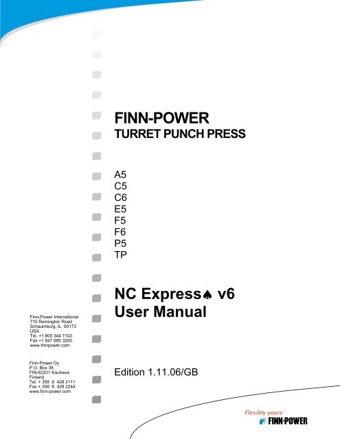
<strong>Finn</strong>-<strong>Power</strong> <strong>International</strong><br />
710 Remington Road<br />
Schaumburg, IL 60173<br />
USA<br />
Tel. +1 800 344 7143<br />
Fax +1 847 885 3200<br />
www.finnpower.com<br />
<strong>Finn</strong>-<strong>Power</strong> Oy<br />
P.O. Box 38<br />
FIN-62201 Kauhava<br />
Finland<br />
Tel. + 358 6 428 2111<br />
Fax + 358 6 428 2244<br />
www.finn-power.com<br />
FINN-POWER<br />
TURRET PUNCH PRESS<br />
A5<br />
C5<br />
C6<br />
E5<br />
F5<br />
F6<br />
P5<br />
TP<br />
NC Express♠ v6<br />
User Manual<br />
Edition 1.11.06/GB
This document contains proprietary information and trade<br />
secrets and is not to be distributed, published or copied partially or<br />
fully without prior written authorization by Lillbacka Corporation.<br />
All registered names and trademarks referred to in this<br />
documentation are sole property of their respective owners.<br />
This documentation includes listed items and their operation descriptions, procedures, and other<br />
exclusive information that are proprietary information and/or intellectual property of <strong>Finn</strong>-<strong>Power</strong><br />
Group, protected under international copyright or similar laws and/or by patents or patents<br />
pending. Listed items are defined herein to include, but not limited to: components, features,<br />
modules, methods, software, systems, technology, options and the like. Further information of<br />
said patents and patents pending can be requested in writing from:<br />
Director of Engineering, Lillbacka Corporation, P.O. Box 38, 62201 Kauhava, Finland.<br />
1-2
1 INTRODUCTION _______________________________________ 1-8<br />
2 SETTING UP NC EXPRESS ______________________________ 2-9<br />
2.1 TOOLING ________________________________________________________2-9<br />
2.1.1 TOOL LIBRARY________________________________________________________ 2-9<br />
2.1.1.1 ADD/MODIFY NORMAL TOOLS _________________________________________ 2-10<br />
2.1.1.1.1 EXERCISE- CREATING NORMAL TOOLS _______________________________ 2-10<br />
2.1.1.1.2 CALCULATION FOR STROKE LENGTH___________________________________ 2-11<br />
2.1.1.2 ADD/MODIFY SPECIAL TOOLS _________________________________________ 2-11<br />
2.1.1.2.1 EXERCISE- CREATING SPECIAL TOOLS (CENTERING GEOMETRY) ___________ 2-12<br />
2.1.1.2.2 MODIFYING SPECIAL TOOLS _________________________________________ 2-14<br />
2.1.2 SETTING DIE CLEARANCES _____________________________________________ 2-15<br />
2.1.3 NETWORKING TOOL LIBRARY (SHARING) __________________________________ 2-17<br />
2.1.4 BACKING UP TOOL LIBRARY ____________________________________________ 2-18<br />
2.1.5 RESTORING OLD TOOL LIBRARY _________________________________________ 2-18<br />
2.2 TURRET SETUP __________________________________________________2-18<br />
2.2.1 TURRET(S) WITHIN NC EXPRESS _________________________________________ 2-19<br />
2.2.1.1 TEMPLATE TURRET __________________________________________________ 2-19<br />
2.2.1.2 MULTIPLE TURRET LAYOUTS __________________________________________ 2-19<br />
2.2.1.3 SHARING TURRET LAYOUTS ___________________________________________ 2-20<br />
2.2.1.4 IMPORTING A TURRET LAYOUT ________________________________________ 2-20<br />
2.2.2 EDIT STATION SETTINGS (LOADING TOOLS) ________________________________ 2-20<br />
2.2.2.1 STATION TYPE______________________________________________________ 2-21<br />
2.2.2.2 KEYS _____________________________________________________________ 2-21<br />
2.2.2.3 LOAD ANGLE_______________________________________________________ 2-21<br />
2.2.2.4 DIE CLEARANCE ____________________________________________________ 2-21<br />
2.2.2.5 OPEN STATION _____________________________________________________ 2-21<br />
2.2.2.6 TOOL LOCKED______________________________________________________ 2-22<br />
2.2.2.7 CLAMP PROTECTION AREA ____________________________________________ 2-22<br />
2.2.2.8 SLEEVES USED FOR TOOLING/NORMAL TOOLS IN AUTO INDEX STATIONS _______ 2-22<br />
2.2.3 EXERCISE- SETTING UP A TURRET ______________________________________ 2-23<br />
2.2.4 TAPPING TURRET (OPTIONAL) ___________________________________________ 2-24<br />
2.3 MACHINE PARAMETERS ___________________________________________2-24<br />
3 STARTING TO USE NC EXPRESS _______________________ 3-25<br />
3.1 LOADING MACHINE WITHIN NC EXPRESS _____________________________3-25<br />
3.2 STARTING NC EXPRESS (ENVIRONMENT) _____________________________3-25<br />
3.3 MATERIALS DATABASE (CAM.MDB) _________________________________3-26<br />
3.3.1 MATERIAL __________________________________________________________ 3-27<br />
3.3.2 UPDATING MATERIALS ________________________________________________ 3-27<br />
3.4 CREATE NEW PART_______________________________________________3-28<br />
1-3
4 PART PREPARATION _________________________________ 4-30<br />
4.1 CAD FEATURES__________________________________________________4-30<br />
4.2 IMPORT DXF ____________________________________________________4-30<br />
4.2.1 IMPORT GOOD DXF ___________________________________________________ 4-30<br />
4.2.2 DXF FILES THAT ARE NOT OK __________________________________________ 4-31<br />
4.2.2.1 DUPLICATE LINE SEGMENTS___________________________________________ 4-31<br />
4.2.2.2 DUPLICATE LINES (AUTOMATICALLY TAKEN OUT)_________________________ 4-32<br />
4.2.2.3 OPEN CONTOUR_____________________________________________________ 4-33<br />
4.2.3 EXERCISE- DXF IMPORT ______________________________________________ 4-34<br />
4.3 CP FILE (PART FILE) _____________________________________________4-35<br />
4.3.1 PART PROPERTIES ____________________________________________________ 4-35<br />
4.3.1.1 EXERCISE- PART PROPERTIES ________________________________________ 4-35<br />
4.3.2 IMPORTING A DXF FROM FLAT __________________________________________ 4-37<br />
4.3.2.1 EXERCISE- IMPORT DXF 2 ___________________________________________ 4-37<br />
4.3.3 STORING CP FILES ____________________________________________________ 4-38<br />
4.3.3.1 EXERCISE- CHANGING DEFAULT PART DIRECTORY _______________________ 4-38<br />
4.3.3.2 NETWORKING PART DIRECTORY (SHARING) ______________________________ 4-39<br />
4.3.4 PARTS DATABASE ____________________________________________________ 4-39<br />
4.3.4.1 ADDING PARTS TO THE DATABASE______________________________________ 4-40<br />
4.3.4.2 CLEANING DATA WITHIN THE DATABASE ________________________________ 4-41<br />
4.3.4.3 EDITING PARTS WITHIN THE DATABASE__________________________________ 4-41<br />
4.3.4.4 SORTING PART INFORMATION WITHIN THE DATABASE ______________________ 4-42<br />
4.3.5 SUPER PART REPORTING (GRID PARTS FEATURE)____________________________ 4-42<br />
4.4 AUTOMATIC TOOLING (AUTOTOOL) _________________________________4-43<br />
4.4.1 CAM DATABASE (CAM.MDB)___________________________________________ 4-43<br />
4.4.1.1 SAVING SETTINGS TO CAM DATABASE __________________________________ 4-43<br />
4.4.2 SETTINGS ___________________________________________________________ 4-44<br />
4.4.2.1 GENERAL TAB ______________________________________________________ 4-44<br />
4.4.2.2 DESTRUCT TAB _____________________________________________________ 4-44<br />
4.4.2.3 MICROJOINT TAB ___________________________________________________ 4-44<br />
4.4.2.4 SETTINGS TAB ______________________________________________________ 4-45<br />
4.4.3 VARIATIONAL TOOLING________________________________________________ 4-45<br />
4.4.4 SORTING ____________________________________________________________ 4-46<br />
4.4.4.1 AUTOMATIC ROBOT PLACEMENT _______________________________________ 4-46<br />
4.4.5 PRESHEARED PARTS (SIZED PARTS)_______________________________________ 4-47<br />
4.4.6 COMMON LINE PARTS _________________________________________________ 4-47<br />
4.4.7 SINGLE PART ________________________________________________________ 4-47<br />
4.4.7.1 EXERCISES- AUTOTOOLING A PART ___________________________________ 4-47<br />
4.4.7.1.1 EXERCISE 1- APPLY TOOLING _______________________________________ 4-48<br />
4.4.7.1.2 EXERCISE 2- DESTRUCT CUTOUT/NOTCH______________________________ 4-50<br />
4.4.7.1.3 EXERCISE 3- APPLYING MICROJOINTS ________________________________ 4-52<br />
4.5 TEACH CYCLES __________________________________________________4-54<br />
4.5.1 EXERCISE- TEACH CYCLES ____________________________________________ 4-57<br />
4.6 INTERACTIVE TOOLING (MANUAL) __________________________________4-60<br />
4.6.1 INTERACTIVE TOOLING ________________________________________________ 4-60<br />
4.6.1.1 EXERCISE- PUNCH ON SEGMENT (SINGLE PUNCH) ________________________ 4-60<br />
4.6.1.1.1 REPLACE TOOLING (EDIT – REPLACE)__________________________________ 4-62<br />
4.6.1.2 EXERCISE- NIBBLING _______________________________________________ 4-62<br />
1-4
4.6.1.3 DESTRUCT _______________________________________________________ 4-65<br />
4.6.2 TEXT MARKING ______________________________________________________ 4-68<br />
4.6.3 MANUAL CYCLING____________________________________________________ 4-69<br />
4.6.4 ROBOT UNLOADING (OPTIONAL)_________________________________________ 4-73<br />
4.6.5 MODIFY TOOLING FEATURES____________________________________________ 4-75<br />
4.6.5.1 TOOL PATH ________________________________________________________ 4-75<br />
4.6.5.2 SORTING __________________________________________________________ 4-77<br />
4.6.5.3 PUNCHING TABS ____________________________________________________ 4-77<br />
5 NESTING _____________________________________________ 5-78<br />
5.1 NC EXPRESS NESTING THEORY _____________________________________5-78<br />
5.1.1 PLATES DATABASE ___________________________________________________ 5-78<br />
5.1.2 PARTS DATABASE ____________________________________________________ 5-79<br />
5.1.3 PLATE DEFINITIONS ___________________________________________________ 5-80<br />
5.1.3.1 CLAMP INFORMATION ________________________________________________ 5-80<br />
5.1.3.1.1 SET TO DEFAULT (AUTOMATIC) ______________________________________ 5-80<br />
5.1.3.1.1.1 PIN2 (PIN3 & PIN4 ONLY C MACHINE)_______________________________ 5-80<br />
5.1.3.1.1.2 NEST UNDER CLAMPS _____________________________________________ 5-80<br />
5.1.3.1.2 MANUAL CLAMP POSITIONING _______________________________________ 5-81<br />
5.1.3.2 PLATE MARGINS ____________________________________________________ 5-81<br />
5.1.4 NESTING THEORY SUMMARY____________________________________________ 5-82<br />
5.2 SETTINGS WITHIN NEST DIALOG ____________________________________5-82<br />
5.2.1 PART SEPARATION ____________________________________________________ 5-82<br />
5.2.2 NEST ACCURACY _____________________________________________________ 5-82<br />
5.2.3 TEMPLATE TURRET ___________________________________________________ 5-83<br />
5.2.4 NEST DIRECTION _____________________________________________________ 5-83<br />
5.2.5 NEST IN ZONES_______________________________________________________ 5-83<br />
5.2.6 GRID NESTING _______________________________________________________ 5-83<br />
5.2.7 NEST BY WORK ORDER ________________________________________________ 5-83<br />
5.2.8 NEST IN HOLES_______________________________________________________ 5-83<br />
5.3 PART ROTATION (GRAIN RESTRICTION) ______________________________5-83<br />
5.4 VARIATIONAL NESTING (USE SMALLEST) _____________________________5-84<br />
5.4.1 PLATE LIST- SET PLATE LIMIT___________________________________________ 5-84<br />
5.5 SETTING UP NEST ENVIRONMENT____________________________________5-85<br />
5.5.1 RUN NUMBER________________________________________________________ 5-85<br />
5.5.1.1 RE-USING/OVERWRITING RUN FOLDERS (DYNAMIC NESTING) ________________ 5-85<br />
5.5.1.2 KEEPING OLD RUN FOLDERS (STATIC NESTS) _____________________________ 5-86<br />
5.5.2 NOTES______________________________________________________________ 5-86<br />
5.5.3 DIE CLEARANCES_____________________________________________________ 5-86<br />
5.6 AUTOMATIC NESTING (EXERCISE) ___________________________________5-86<br />
5.6.1 EXERCISE 1- SINGLE PART NEST _________________________________________ 5-86<br />
5.7 COMMON LINE NESTING (PUNCH TOOLING ONLY) ______________________5-92<br />
5.7.1 TYPES OF PARTS______________________________________________________ 5-92<br />
5.7.2 ACTIVATING COMMON LINE ____________________________________________ 5-92<br />
5.7.3 EXERCISE 2- COMMON LINE NESTING _____________________________________ 5-93<br />
5.8 RE-OPENING AN OLD NEST _________________________________________5-94<br />
5.9 MODIFYING PART’S/TOOLING (FOR PARTS THAT ARE ALREADY NESTED) ____5-95<br />
5.10 PRESHEARED PLATE NESTING _____________________________________5-95<br />
1-5
5.11 INTERACTIVE NESTING ___________________________________________5-95<br />
5.11.1 NESTING AN EMPTY PLATE ____________________________________________ 5-95<br />
5.11.2 DRAG AND DROP PARTS_______________________________________________ 5-96<br />
5.11.3 COPY PARTS ________________________________________________________ 5-96<br />
5.11.3.1 MOVE SELECTED___________________________________________________ 5-96<br />
5.11.4 ADD PART _________________________________________________________ 5-96<br />
5.11.5 RETOOL NEST (INTERACTIVE) __________________________________________ 5-96<br />
6 OPTIMIZATION_______________________________________ 6-97<br />
6.1 AUTOMATIC OPTIMIZATION________________________________________6-97<br />
6.1.1 PUNCH OPTIMIZER ____________________________________________________ 6-98<br />
6.1.1.1 TOOL GROUPS ______________________________________________________ 6-98<br />
6.1.1.1.1 GROUP TOOLS ORDER OPTION________________________________________ 6-99<br />
6.1.1.2 CLAMP OPTIONS FOR STANDALONES ____________________________________ 6-99<br />
6.1.1.3 SHEET UNLOAD (C5 ONLY) ___________________________________________ 6-99<br />
6.1.1.4 COMPONENT UNLOADING ORDER_______________________________________ 6-99<br />
6.1.1.5 PLATE TOOLS VIEW ________________________________________________ 6-100<br />
6.1.1.6 CONTROL PARAMETERS _____________________________________________ 6-101<br />
6.1.1.6.1 STABILITY AREA _________________________________________________ 6-101<br />
6.1.1.6.2 STYLE __________________________________________________________ 6-102<br />
6.2 EXERCISE- AUTOMATIC OPTIMIZATION ___________________________6-103<br />
6.3 BATCH OPTIMIZATION (AUTO-PROCESSING MULTIPLE SHEETS) _________6-107<br />
6.4 RETOOL NEST (AUTOMATIC) ______________________________________6-109<br />
6.4.1 DOUBLE HIT REMOVAL _______________________________________________ 6-109<br />
6.4.2 PUNCH COMMON LINE HIT REMOVAL (PUNCH ONLY) _______________________ 6-109<br />
6.5 PRESHEAR OPTIMIZER (CUT TO SIZE SHEETS) ________________________6-109<br />
6.6 INTERACTIVE OPTIMIZER_________________________________________6-109<br />
6.6.1 MODIFY ___________________________________________________________ 6-110<br />
6.6.2 VIEW ONLY ________________________________________________________ 6-110<br />
6.7 INTERACTIVE ZONES_____________________________________________6-110<br />
6.8 ADVANCED TRAINING (INTERACTIVE OPTIMIZER & INTERACTIVE ZONES) _6-111<br />
7 SIMULATOR_________________________________________ 7-113<br />
7.1 USING THE SIMULATOR___________________________________________7-113<br />
7.2 SIMULATING DESIRED TOOLS (TOOL LIST)___________________________7-114<br />
8 POST PROCESSING (CREATE NC CODE)_______________ 8-115<br />
8.1 CREATE NC CODE_______________________________________________8-115<br />
8.1.1 MODIFYING NC FILE NAME AND LOCATION _______________________________ 8-115<br />
8.1.2 EXTRA TIME SETTINGS _______________________________________________ 8-116<br />
9 OPTIONS AND REPORTS _____________________________ 9-117<br />
1-6
9.1 USE SPLIT-SCREEN PART DIALOG __________________________________9-119<br />
9.1.1 REMOVING PARTS FROM LIST __________________________________________ 9-119<br />
9.1.2 SAVING MODIFIED PART LIST __________________________________________ 9-119<br />
9.1.3 CLOSING THE SPLIT-SCREEN ___________________________________________ 9-120<br />
9.2 REPORTS (SETUP SHEET) _________________________________________9-120<br />
9.2.1 NEST REPORT _______________________________________________________ 9-120<br />
9.2.2 JOB SHEET _________________________________________________________ 9-120<br />
9.2.3 REPORT____________________________________________________________ 9-120<br />
9.2.3.1 SELECTING A REPORT TYPE __________________________________________ 9-120<br />
9.2.3.2 SAVING A REPORT__________________________________________________ 9-120<br />
9.2.3.3 PRINTING THE REPORT ______________________________________________ 9-121<br />
9.2.3.4 COPY THE REPORT _________________________________________________ 9-121<br />
10 ORDERS MANAGEMENT SYSTEM (MRP NESTING)___ 10-122<br />
10.1 DATABASE ORDERS DIALOG_____________________________________10-122<br />
10.2 ADDING/MODIFYING PARTS IN ORDERS DATABASE __________________10-123<br />
10.3 EXERCISE- USING ORDERS DATABASE_____________________________10-126<br />
11 APPENDIX A- MODIFY TOOLING ___________________ 11-129<br />
12 APPENDIX B- SPECIAL TOOL INFORMATION _______ 12-135<br />
13 APPENDIX C- DIE CLEARANCE SUGGESTIONS ______ 13-138<br />
14 APPENDIX D- AUTOTOOL SETTINGS________________ 14-140<br />
15 APPENDIX E- INTERACTIVE OPTIMIZER ___________ 15-144<br />
16 APPENDIX F- INTERACTIVE ZONES SETTINGS ______ 16-147<br />
1-7
1 INTRODUCTION<br />
W elcome to NC Express integrated part creation and nesting system. NC<br />
Express is an easy to use Windows-based application. Any computer<br />
running Microsoft® Windows NT 4.0/2000/XP Professional operating systems can<br />
install and use this software*. NC Express follows the conventions of a<br />
contemporary Windows based application. Therefore, any <strong>user</strong> familiar with<br />
Microsoft® Office Suite or Windows operating systems should already have all the<br />
knowledge necessary to work with this package. Although a working knowledge of<br />
these programs is beneficial it is not a prerequisite to using NC Express.<br />
NC Express is a scalable application. It may be used as a single part drafting and<br />
tooling program or as a fully automated <strong>machine</strong> tool management system. Either<br />
way the results will be the same, automatic NC code creation. Users are easily<br />
guided through the process of creating NC code. When first started the <strong>user</strong> will<br />
notice the ease of use, with the program’s menu-driven system. Each section of the<br />
system is divided throughout the program. What makes NC Express unique is that<br />
the system is driven to form a state of automation. The NC Express <strong>user</strong> can import<br />
or draw geometry and process it into NC code without any <strong>manual</strong> intervention.<br />
*NC Express does not run on Windows 95/98/Me.<br />
1-8
2 SETTING UP NC EXPRESS<br />
The initial setup of NC Express is very important to the customer. There are three<br />
important items in NC Express that work together to create the working environment<br />
for the <strong>user</strong>. Tool library, Turret setup, and Machine Parameters must be setup<br />
correctly to output the desired NC code.<br />
There is also a correlation between tool setup (potential of using tool), the turret setup<br />
(capability to use tools) and optimization process (execution of tooling). In tool<br />
setup, parameters and characteristics are assigned that define where and how a tool<br />
can be used. In turret setup a configuration of <strong>machine</strong> capability is viewable in<br />
terms of quantity of stations, their sizes and their unique functions (forming,<br />
punching, indexablity…). Optimization uses the information from both of these and<br />
creates <strong>machine</strong> able results.<br />
The <strong>user</strong>, in order to get desired results from NC Express, must understand this<br />
correlation and define the machining conditions properly. The first item to define is a<br />
tool library. The <strong>user</strong> begins by building a tool library. Each tool to be used must be<br />
entered within. When done building the tool library, the tools must be assigned to<br />
where they will be used in the physical <strong>machine</strong> turret. The following section will<br />
cover setting up basic tools, special tools, and multi-tools; and how to place them into<br />
NC Express turret layout. Once tooling and turret information is explained the<br />
following section will explain starting to use NC Express.<br />
2.1 Tooling<br />
Within NC Express there are two types of tools defined- normal tools and special<br />
tools. Normal tools consist of Round, Rectangle, Square, Obround, Square radius,<br />
Rectangle radius, Shear, and Laser. Some special tools can be created through NC<br />
Express’ parametric tool creation or a DXF file containing the geometry of the tool<br />
can be imported.<br />
If NC Express asks for Die Clearance when first opened please go to Die<br />
Clearances section before setting tools.<br />
2.1.1 Tool Library<br />
The NC Express Tool library is a database format (.mdb) file created to store all<br />
pertinent data about tools loaded within the system. All information for tools is in<br />
database format to create a more stable working environment. More database<br />
information will be covered later in this chapter.<br />
The following two sections (2.1.1.1 & 2.1.1.2) will cover adding normal and special<br />
tools into the tool library.<br />
2-9
2.1.1.1 Add/Modify Normal Tools<br />
To open the tool library in NC Express go to Settings menu | select Tool library.<br />
Again normal tools consist of Round, Rectangle, Square, Obround, Square<br />
radius, Rectangle radius, Shear, and Laser. Normal tools can be created or<br />
modified within the tool library in NC Express by selecting New, to create, or<br />
highlight tool and select Modify, to modify. If tool no longer exists this tool<br />
may be easily deleted out of the tool library by clicking Delete button when<br />
specified tool is selected.<br />
Parameters<br />
(See appendix A for all definitions of parameters in Modify Tool screen.<br />
Additional information can be found in NC Express Help documentation<br />
by pressing F1.)<br />
2.1.1.1.1 EXERCISE- Creating Normal Tools<br />
In the following exercise two tools will be created: one square and one<br />
rectangle.<br />
Step 1: Open Tool Library<br />
Go to Settings menu | Tool library…<br />
Step 2: Create new tools, follow bullet points below:<br />
Select New…<br />
Tool ID- RECT_0.250X1.000 (5mmX25mm)<br />
Tool type- Rect<br />
Length- 1.0” (25.0mm)<br />
Width- 0.25” (5.0mm)<br />
Tool size- B<br />
Set keys/slot to 0 and 90<br />
Index- Auto index<br />
Dies- click Add die…<br />
o Type 0.006” (0.15mm), click OK<br />
o Click Add again, Type 0.012” (0.30mm)<br />
Nibble/<strong>Punch</strong> priority- 5<br />
Stripper Height, RAM speed, Acceleration, <strong>Punch</strong> Depth-0<br />
o Note- setting zero for these values will use default values output<br />
in the NC program*<br />
<strong>Punch</strong> count- 1 (how many of these tools exist)<br />
Give optimizing group- REGULAR<br />
Select punching from control mechanism<br />
Click OK. Then save.<br />
*Default values for RAM Speed and Acceleration are calculated using the<br />
sheet weight (thickness * L * W). Stroke length will be output<br />
automatically based on material thickness. If these values are changed<br />
within the Tool library the values will be output in the NC program for that<br />
tool when it is used.<br />
2-10
2.1.1.1.2 Calculation for Stroke Length<br />
Within <strong>machine</strong> parameters are values that allow for the calculation of the<br />
stroke length within the code. The two parameters are ‘Fixed Offset’ and<br />
‘Multiplication Factor’. The multiplication factor is multiplied by the<br />
thickness of the material and then the Offset factor is added to give the final<br />
stroke length for the program.<br />
[(Stroke Length Multiplication Factor X material thickness (metric value) +<br />
Stroke Length Fixed Offset = Stroke Length]<br />
Exercise Con’t…<br />
Step 3: Reopen Tool library…<br />
Select New…<br />
Tool ID- SQ_0.500 (SQ_12.0)<br />
Tool type- Sqr<br />
Length- 0.5” (12mm)<br />
Corner radius/Design angle- 0<br />
Tool size- B<br />
Dies- click Add die…<br />
o Type 0.006” (0.15mm), click OK.<br />
o Again click Add die, Type 0.012” (0.30mm) click OK.<br />
Nibble/<strong>Punch</strong> priority- 5<br />
Stripper Height- 200<br />
RAM Speed- 80*<br />
Acceleration- 80<br />
<strong>Punch</strong> Depth- 0<br />
Give optimizing group- REGULAR<br />
Select PUNCHING from control mechanism*<br />
Click OK. Then save.<br />
*RAM Speed is controlled from the control mechanisms list on 11<br />
series and up <strong>machine</strong>s as PUNCH_SPEED. Two values are entered<br />
for PUNCH_SPEED.<br />
2.1.1.2 Add/Modify Special Tools<br />
Special tools can easily be created in NC Express through an easy to use dialog.<br />
Go to File menu | Add special tool. Dialog will ask which type of special tool<br />
will be added, select tool type, and then input the settings. For more intricate<br />
special tools (arbitrary), a DXF file can be used to import a special tool.<br />
A special tool is a tool that does not conform to the following regular shapes:<br />
Round, Square, Obround, Rectangle. NC Express defines more commonly<br />
used special tools in a parametric library viewable when ‘add special tool’ is<br />
selected. NC Express parametric tools are defined for 4 way radius, Banana, Dtool,<br />
Micro-joint (trapezoid), multi-radius, Tapping, wheel tools, and triangle.<br />
For all other shapes a drawing must be provided in the form of a DXF or drawn<br />
within NC Express.<br />
2-11
(Note- For arbitrary tool, new drawing or DXF must be on the screen before<br />
selecting arbitrary. In addition all arbitrary shapes must have the center of the<br />
tool at the 0,0 origin and must contain a single external contour with no open or<br />
internal contours.)<br />
Automatic create<br />
Import DXF<br />
Parameters<br />
(See Appendix B for settings of special tools. Additional information can also<br />
be found in Help documentation in NC Express by pressing F1.)<br />
2.1.1.2.1 EXERCISE- Creating Special Tools (Centering<br />
Geometry)<br />
The following exercise will walk through the process of adding special tools<br />
to the tool library. First two examples will demonstrate how to add a special<br />
tool using parametric add special tool. Second, will show the ability to<br />
import a DXF file, center geometry, and add geometry as special tool.<br />
Step 1: New Special Tool<br />
Go to File menu | Add special tool<br />
Step 2: Creating new special tools:<br />
Step 2a: 4 Way Radius tool, follow bullet points:<br />
Select 4 Way Radius<br />
Enter values shown on next page<br />
L- 1” (25mm)- Length of tool<br />
R- 0.2” (5mm)- radius of arc<br />
D- 0.1” (2.5mm)- length of extension from arc to edge of tool.<br />
Click OK.<br />
Next screen will allow settings for special tool.<br />
Tool name- 4RAD_1.0 (for mm 4RAD_25.0)<br />
Select square symmetry click OK.<br />
Note- there is no need to change exit direction, these settings are for<br />
forming tools.<br />
Setup tool to specifics below:<br />
o Tool size- B<br />
o Add die- 0.006 (0.15mm)<br />
2-12
o Optimization group- REGULAR<br />
o Control- PUNCHING<br />
Click OK<br />
Step 2b: Multi-radius tool<br />
Go to File menu | Add special tool…<br />
Select Multi-radius<br />
Enter values from picture below…<br />
Click OK.<br />
Next screen will allow settings for special tool<br />
Tool name- MRAD_0.25 (MRAD_6)<br />
Select No symmetry<br />
Click OK.<br />
Set settings for tool<br />
o Tool size- B<br />
o Add die- 0.006 (0.15mm)<br />
o Optimization group- REGULAR<br />
o PUNCHING<br />
Click OK.<br />
Step 2c: Import DXF and center tool’s geometry:<br />
Note- When importing DXF files as special tools it is important to make<br />
sure the center point of the geometry is correct. The center point of the<br />
geometry will be actual center point of the tool at the <strong>machine</strong>. The<br />
following will show how to make the change within NC Express; this can be<br />
done more than one time if a special tool needs to be fixed.<br />
Create New Part<br />
Import DXF Louver.dxf<br />
When Louver.dxf is imported find the origin point. Origin point is<br />
defined by yellow diamond (shown below).<br />
2-13
Where the origin is within the geometry of the tool is where the center<br />
point of the tool will be defined. (Center point of the physical punch<br />
tool)<br />
Go to File menu | add special tool<br />
Click Arbitrary (this will only work if geometry [closed single<br />
contour] is on the screen.)<br />
Setup special tool:<br />
o Tool name- LOUVER<br />
o No symmetry<br />
o Leave DUMMY for alternatives to the tool<br />
o (A) Exit direction Angle- 90<br />
o (B) Exit Path length- .2 (5mm)<br />
o (C) Protection Area Length- 2.8 (71mm)<br />
o (D) Protection Area Width- 0.4 (10mm)<br />
o No offsets<br />
o Click OK.<br />
Setup tool settings:<br />
o Tool size- C<br />
o Add die- 0.006 (0.15mm)<br />
o Add die- 0.012 (0.30mm)<br />
o Stripper Height- 200<br />
o RAM Speed- 70<br />
o Acceleration- 50<br />
o Optimization group- FORMING<br />
o Control Mechanism- PUNCHING<br />
Each different type of control mechanism has specific parameters for its<br />
type; a description of each mechanism exists in Appendix A<br />
Click OK.<br />
2.1.1.2.2 Modifying Special Tools<br />
To modify special tool information, as far as, symmetry, form protection<br />
area, or alternatives to the tool you must go to File menu | open part. Then<br />
go to SPTOOLS folder, within current <strong>machine</strong> folder, and open special tool<br />
CP file that will be modified. Once opened, go to File menu | add special<br />
tool, click Arbitrary. This will bring Special Tool Information screen up to<br />
change settings, then click OK when finished.<br />
If a special tool’s center point needs to be modified after it has been entered<br />
into NC Express. Open special tool CP file and make proper modification.<br />
When finished modifying center point go to File menu | select Add special<br />
tool, click Arbitrary and then click OK on special tool information dialog.<br />
2-14
NOTE- If the tool’s center point has been changed all parts that have used<br />
the tool will need to be re-tooled for only the special tool that has changed.<br />
2.1.2 Setting Die Clearances<br />
NC Express keeps track of die clearances for each tool in the tool library. Each tool<br />
will have dies declared and each material type will have a die clearance range set.<br />
Setting the die clearance range will allow for use of tools which have a die that falls<br />
between the lower and upper limit set for the die range. The following explains<br />
how the dies can be set in NC Express and how to set the die range.<br />
Step 1: Setting Dies for each tool<br />
If no Tool library database exists, on first<br />
open of NC Express you will be asked to<br />
enter a die clearance (shown right). What<br />
will happen when you click OK is that the<br />
die clearance you entered will be added as<br />
default for all tools in the tool library. At this point, choose a die clearance that will<br />
work for all or most tools in your tool library. More than one default die clearance<br />
may be added at this point, click Yes to add another die clearance. Note- Adding a<br />
default die clearance adds to all tools. If you have added the die clearance to all and<br />
some may not have that die you will have to open the tool library and delete the<br />
undesired die per tool.<br />
Remember- The first time you open NC Express after the update will ask for the<br />
die clearances. Die clearances can be added <strong>manual</strong>ly also.<br />
Manually editing<br />
Adding- Above shows how to add a die to a tool <strong>manual</strong>ly. Open a tool in the tool<br />
library, click add die, then type the value for the die. Two similar tools can be setup<br />
2-15
once in NC Express tool library, example, two rectangle 0.25x1.00 with two of the<br />
same dies- Open RE_0.250x1.000 (5mmx25mm) highlight the die quantity and<br />
change the quantity value to two (2). Also, change punch count on bottom of<br />
modify tool to two (2). You now just told NC Express that there are two<br />
RE_0.250X1.000 (5mmx25mm) tools to be loaded in the turret; one can be loaded<br />
in the turret at 0° and one at 90° if desired.<br />
<strong>Punch</strong> count determines the amount of one specific tool in the tool library. Tool<br />
library may have a tool with 4 different die clearances and only 3 punch counts-<br />
This means that the tool can only be loaded in the turret a maximum of three (3)<br />
times.<br />
Removing- To remove a die clearance for a tool select the die, for the specific die<br />
value that will be removed, and click remove die.<br />
Remember- When using this feature in NC Express this requires proper setup<br />
initially. Each tool in the tool library will need to have all the correct physical dies<br />
(meaning at the <strong>machine</strong> which type of die the tool physically has).<br />
After die clearances are set, open the tool library and click Save. (Note- If NC<br />
Express asks for a default die clearance every time it is opened <strong>user</strong> did not save the<br />
tool library, clicking save will create tool library database (*.mdb) which will allow<br />
for editing in Microsoft Access.)<br />
Step 2: Setting die range for materials<br />
At this point all dies should be entered for tools. What needs to be done now is to<br />
set the die clearance range for all material types and thickness. (At the end of this<br />
document Appendix C shows recommended die clearances and ranges for all<br />
materials)<br />
2-16
Go to Settings menu | Machine Parameters - Environment. Below shows a picture<br />
of setting die clearance ranges:<br />
Above the left number is the lower limit and the right is the upper limit.<br />
Above, assume the current die clearance set for each tool is 0.005” (0.12mm), this<br />
value falls within the range for this specific material thickness. All tools with a die<br />
clearance between 0.004-0.009 (0.1mm-0.22mm) can be used. If all tools would<br />
have a 0.003 (0.08mm) die clearance no tools would be used at all. The theory- if a<br />
tool does not have a die clearance set to fall within the range (per thickness) in the<br />
Environment screen; it will not be used when tooling a part at that specific<br />
thickness.<br />
Remember- If the tooling die doesn’t fall between the lower and upper limit of the<br />
die clearance range, the tool will not be seen in the select tool screen and will not be<br />
used from the turret/tool library.<br />
Note- To bypass the use of dies in NC Express one die must be set for all tooling<br />
and the die range for all material thickness must be set to open the specific die.<br />
2.1.3 Networking Tool Library (Sharing)<br />
Because the tool library within NC Express exists as a Microsoft Access database,<br />
the database and files that pertain to it may be transferred to a desired location (i.e.<br />
network drive) to be shared amongst one to many <strong>user</strong>s. To share the database one<br />
must copy the LIB and SPTOOLS folders, which holds the tool library database and<br />
special tool settings, to shared folder (i.e. on network or PC). The two folders<br />
reside in the <strong>machine</strong> specific folder in NC Express. (Note- Network Administrator<br />
should be involved in this process.)<br />
2-17
Process of sharing<br />
Step 1: Decide on where files will be shared to other <strong>user</strong>s.<br />
a. Network drive (Network administrator will map this location.)<br />
b.Or, Main programming computer (note- if sharing from main computer the<br />
folder must be shared for others to see. Speak with network administrator<br />
to handle this function.)<br />
Step 2: Copy LIB and SPTOOLS folders to shared location.<br />
Go to C:\fms\ncexpress\”<strong>machine</strong>”.<br />
Copy the LIB and SPTOOLS folder (all contents) from the “<strong>machine</strong>” folder.<br />
Paste the contents into the shared location.<br />
Step 3: Map NC Express tool library to database location.<br />
Open NC Express, go to Settings menu | Machine Parameters – select<br />
Environment…<br />
Select Browse… within the Tool library directory section.<br />
Find shared location through windows file structure then select database, click<br />
open.<br />
Step 4: Click Save, to save tool library.<br />
Repeat for all <strong>user</strong>s.<br />
The reason the whole LIB and SPTOOLS folder are copied is that there are special<br />
tool files that are called up when a special tool is used from the tool library.<br />
Without these files the tool library does not know the geometry of these files.<br />
2.1.4 Backing Up Tool Library<br />
It is very important to backup tool library database environment if not already done<br />
by network admin. Copy the LIB and SPTOOLS folders back to main<br />
programming computer or floppy disk. The reason for this is if there is a network<br />
faiLSRe the NC Express <strong>user</strong> still has the ability to continue working on his/her<br />
own computer. Backup can be placed on all other computers when needed, if saved<br />
to a floppy. If the network happens to fail, the database would need to be remapped<br />
back to the LIB and SPTOOLS folders on the PC (see Process above).<br />
2.1.5 Restoring Old Tool Library<br />
If the database has been corrupted by any means and was not backed up there is a<br />
way to restore. Within the LIB folder there is a file named toollib (no file<br />
extension). With this file there and no database, open NC Express. You will have<br />
to set all dies and keys again.<br />
2.2 Turret Setup<br />
In NC Express you will find flexibility and ease of use when setting up the turret for<br />
use in the system. Tools are <strong>manual</strong>ly setup in the system by the <strong>user</strong> within the Tool<br />
library. Using the interactive screens of the turret setup, the <strong>user</strong> can visualize where<br />
the tools lay in the turret. Tools can be added to the turret <strong>manual</strong>ly, or if setup<br />
properly the <strong>user</strong> can opt to load stations automatically when optimizing a plate.<br />
2-18
2.2.1 Turret(s) within NC Express<br />
To find the turret layout within NC Express <strong>user</strong> must go to Settings menu | select<br />
Turret… Once opened the dialog shown below is opened.<br />
Screen shot above shows that there is one turret setup, named ‘turret’. When NC<br />
Express is first installed there is a default empty turret ‘turret’, which has the correct<br />
station layout relevant to the customer <strong>machine</strong>. Current turret displays each turret<br />
created within NC Express; and Turret/Multi-tool setup displays the ‘Main’ layout<br />
as well as multi-tool stations within (which can be viewed by selecting them). To<br />
view a turret, first select a ‘Current turret’ and then select which station type to<br />
view (main being all stations within turret) and click View. Clicking View will<br />
display a bird’s eye view of the turret layout for the <strong>user</strong> (selecting Modify will<br />
view a list instead of graphical view).<br />
2.2.1.1 Template Turret<br />
The ‘turret’ within the system is the template turret, base turret layout. The<br />
template turret is always where tool station information is taken from when<br />
nesting and optimizing, even when using multiple turret layouts (explained in<br />
the next section). In the case where multiple turrets are used information from<br />
the turret is copied to the template turret and used in nesting and optimizing. If<br />
there is no need for multiple turret layouts then the template turret will be the<br />
turret that is used to input tools and station information.<br />
Note- The template turret ‘turret’ should never be deleted from NC Express.<br />
2.2.1.2 Multiple Turret Layouts<br />
Available within NC Express is the ability to create multiple turret layouts.<br />
Customer specific jobs, Die clearances, or special turret layouts would be some<br />
of the reasons why multiple turret layouts are needed. The ability to have<br />
multiple turrets can save the programmer time when tooling or nesting parts.<br />
For example, if a customer specific job always used the same tools in the same<br />
stations the programmer would then just select the turret within Autotool to<br />
only use tools loaded within the “customer” turret.<br />
2-19
When using multiple turret layouts the template turret ‘turret’ can never be used<br />
as one of the multiple layouts. The ‘turret’ is always the template turret. The<br />
meaning of template turret is that the ‘turret’ will always change when a<br />
different turret layout is used (explained in previous section). Example, if a<br />
new turret was created named ‘CustomerA’ and was used to nest and optimize<br />
plates, the template turret ‘turret’ will have the same tool setup as turret<br />
‘CustomerA’. In the case where template turret has some stations locked is<br />
when ‘CustomerA’ turret would not completely be copied to the template turret.<br />
2.2.1.3 Sharing Turret Layouts<br />
If NC Express is installed on more than one computer the programmer(s) can<br />
share turret layouts amongst each other to alleviate any confusion when<br />
programming parts/plates. Sharing the turret(s) is similar to sharing the Tool<br />
library. User will copy all *.tur files within the <strong>machine</strong> work directory<br />
(C:\fms\(<strong>machine</strong> name)\work) to the shared directory on either PC or network.<br />
Within the Environment (Settings menu | Machine parameters – Environment)<br />
dialog the <strong>user</strong> will find Turret directory…click Browse to find shared directory<br />
where *.tur files were copied to. Once found a *.tur file in the directory will be<br />
selected and then click Open.<br />
All *.tur layouts within the shared directory will be displayed in the Current<br />
turret of Turret Selection. In the case that there are multiple <strong>machine</strong> setups<br />
used in NC Express the *.tur for each <strong>machine</strong> setup should be placed into<br />
separate directories.<br />
2.2.1.4 Importing a Turret Layout<br />
If turret layouts are not shared amongst multiple <strong>user</strong>s or if a backup of a *.tur<br />
file is needed to be brought into the system there is the ability to import turret<br />
layouts. Click Import on Turret Selection dialog and find the *.tur file to be<br />
imported.<br />
2.2.2 Edit Station Settings (Loading Tools)<br />
When a tool is being added to the turret there are settings to modify to create the<br />
correct working environment. Each station has modifications done when placing<br />
tools into them. Below is a screen shot of the Edit Station dialog. The following<br />
items in section 1.2.2 will explain the settings and expected outcomes when used.<br />
2-20
2.2.2.1 Station Type<br />
Station type will never be changed for a specific station. The option is only<br />
available if the administrator <strong>user</strong> ID is entered within the environment. So, if<br />
the <strong>machine</strong>’s actual stations change contact applications support to have this<br />
change made as well.<br />
2.2.2.2 Keys<br />
Displays physical keys of the station. Each station size has set keys within<br />
them. Keys for station will not be changed within NC Express unless<br />
physically changed on the <strong>machine</strong>.<br />
2.2.2.3 Load Angle<br />
Changing the load angle for a tool allows the tool to be used at different<br />
rotations (ex. 0°, 45° or 90°). Keys set for a specific tool within the tool library<br />
in conjunction with the keys in the turret station determine which load angles<br />
are listed in the Load Angle drop down.<br />
Remember- Keys set for tools need to be the same as how the physical tool is<br />
or can be keyed at the <strong>machine</strong>.<br />
2.2.2.4 Die Clearance<br />
Setting the die clearance for a tool loaded in the turret will set the die clearance<br />
for that tool when the turret is used. In the case that the tool has multiple die<br />
clearance set in the Tool library then NC Express will automatically set the die<br />
clearance that is needed for that tool. If multiple tools reside within the turret<br />
and have different die clearances set for them then NC Express will choose the<br />
correct die needed and use that station.<br />
2.2.2.5 Open Station<br />
Clears current tool loaded in the station and opens the station. Removes tool<br />
from station.<br />
2-21
2.2.2.6 Tool Locked<br />
The tool locked feature will lock the station’s currently loaded tool within NC<br />
Express. This does not mean that the tool is physically locked in the <strong>machine</strong>.<br />
When viewing the turret layout the <strong>user</strong> can easily see if a station is locked or<br />
unlocked by the red ring that is placed around the station (shown below).<br />
When Optimization is processing a plate the tools being used on the plate are<br />
checked against the current turret. If all tools in the plate are loaded in the<br />
current turret already the post generates using stations from the current turret.<br />
If a tool is not loaded in the turret, example C auto index station, and all C auto<br />
index stations are locked within the current turret then NC Express will give an<br />
error stating ‘No stations available’. Optimization will be canceled.<br />
Tool locked is typically used in cases where tools will not be changed at the<br />
<strong>machine</strong>. The programmer should have a good line of communication with the<br />
<strong>machine</strong> operator to find which tools primarily will stay in the turret. Once this<br />
is found out the programmer will then lock the selected tools in their respective<br />
stations.<br />
2.2.2.7 Clamp Protection Area<br />
Each station size has it’s own clamp protection area set. The values for the<br />
protection area are preset values done by <strong>Finn</strong>-<strong>Power</strong>, but can be viewed when<br />
opening each different station size. The clamp protection area allows NC<br />
Express to nest tooling near the clamps, which when optimized will recognize<br />
that there is a punch hit within the protection area. When a punch hit is within<br />
the protection area a clamp reposition, move of the clamp carriage, will be done<br />
automatically to make the punch hit.<br />
Note- At the <strong>machine</strong> if a punch hit is found in the clamp protection area the<br />
<strong>machine</strong> will not do this punch hit and would stop the program giving an alarm.<br />
Program would need to be re-created.<br />
The protection area forms an imaginary box around the clamps for each tool<br />
selected/used. The station size is set for each tool within the Tool library.<br />
2.2.2.8 Sleeves Used for Tooling/Normal Tools in Auto Index<br />
Stations<br />
Sleeves<br />
In the case where a smaller tool will be loaded into a larger station (ex. B size<br />
tool will be loaded into a C station). At the <strong>machine</strong> there is a sleeve that will<br />
2-22
e used to allow the B tool to be placed into the turret. When a small tool is<br />
loaded into a larger station NC Express will ask if there is a suitable sleeve for<br />
the tool.<br />
Normal tools in Auto Index station<br />
In the case where a <strong>user</strong> will want to place a defined (in Tool library) nonindexable<br />
tool into an Auto Index station NC Express will ask if this is correct.<br />
2.2.3 EXERCISE- Setting Up a Turret<br />
For the following exercise you will need a printout of the current turret layout of the<br />
<strong>machine</strong>’s turret if you would like to set up a turret of <strong>machine</strong> purchased. Once<br />
printout is obtained all stations can be assigned properly.<br />
The following tutorial will show how to create, setup, and add tools to a new turret<br />
layout in NC Express. Creating a new ‘TEST’ turret will show how to implement<br />
the use of multiple turret setups in NC Express.<br />
Setting up stations<br />
Multi-tool stations<br />
Die clearances in turret<br />
Tapping<br />
Step 1: Open Turret screen<br />
Go to Settings menu | select Turret…<br />
Step 2: Create new turret<br />
Select turret from current turret<br />
Click Save as…<br />
Type name of new turret- TEST<br />
Step 3: Adding a Multi-tool station<br />
The following will demonstrate how to load your multi-tool stations into<br />
the turret accordingly. If not done correctly incorrect clamp protection<br />
areas will be set.<br />
With Main highlighted, click Modify… (There should be 20 stations<br />
set for this turret)<br />
o Select station no. 3<br />
o Set station type- Multi-tool<br />
o Change station name- MT24_8<br />
o Click OK, and then OK again to return to Turret Selection dialog<br />
Highlight newly created- station 3 MT24_8, click Modify…<br />
o Click default setup<br />
o MT24_8.sta file will be automatically loaded into Default file<br />
field. (MT24_8.sta file stores clamp protection area<br />
information for MT24_8 station)<br />
o Set station sizes- MT24_8<br />
o Click OK<br />
2-23
You should now have MT24_8 for station size, meaning that only<br />
MT24_8 type tools will be loaded into this station.<br />
Step 4: Placing tools in turret<br />
For exercise load only 6 tools into the turret to demonstrate how this is<br />
done. Load (1) B size tool, (1) C size tool, (1) special tool, and (3) multitools.<br />
These tools should already exist in the tool library.<br />
Tools can be loaded two different ways:<br />
o One-<br />
Open turret from settings menu<br />
Highlight current turret (TEST)<br />
Highlight main for turret, then click View<br />
Select station by clicking button that says Open<br />
Click Select Tool…<br />
o Two-<br />
Open turret from settings menu<br />
Highlight current turret (TEST)<br />
Highlight main for turret, then click Modify<br />
Highlight station no., click Modify<br />
Click Select Tool…<br />
2.2.4 Tapping Turret (Optional)<br />
Following will demonstrate the process of creating a tapping turret in NC Express.<br />
To activate tapping turret go to Settings menu | Machine parameters > Machine…<br />
Check Tap Head and enter correct settings. Click OK. Restart NC Express. Now<br />
go to Settings menu | Machine parameters and tapping turret will now be available<br />
to select.<br />
Configuring tapping turret<br />
(Tapping turret is very similar to the setup of a Multi-tool station.)<br />
Open tapping turret…<br />
Highlight desired current turret, click Modify.<br />
Click default setup<br />
o The .sta file should automatically be in the Default file field<br />
o Select station sizes- TAP<br />
Tapping is now ready to have tools loaded.<br />
Note- If there is more than one tapping units you may create a turret for each in<br />
NC Express the same way as creating a new turret.<br />
2.3 Machine Parameters<br />
The Machine Setup is essentially a simulation of the working <strong>machine</strong>. This is the<br />
most important part of the system setup. If done incorrectly this can create problems<br />
in the end result. This setup must be done in order to create a template for the system<br />
to follow. The <strong>machine</strong> setup is and will be already done by <strong>Finn</strong>-<strong>Power</strong>.<br />
Information pertaining to each tab in the <strong>machine</strong> parameters setup can be found in<br />
the help documentation in NC Express by pressing F1.<br />
2-24
3 STARTING TO USE NC EXPRESS<br />
Starting to use NC Express requires a few functions by the end <strong>user</strong> after tool and<br />
turret setup. The <strong>machine</strong> parameters are setup by <strong>Finn</strong>-<strong>Power</strong> to declare working<br />
areas of the <strong>machine</strong>, as well as clamp settings and other options of the <strong>machine</strong>. The<br />
<strong>machine</strong> parameters should need no adjusting by the customer.<br />
When the customer has installed NC Express on desired computer* there is a<br />
directory created- C:\fms\ncexpress. Within this directory there is a bin directory,<br />
which holds all pertinent files for NC Express to run. Customer <strong>machine</strong> (ex.<br />
laser_mm or ‘customer name’) will be stored in the C:\fms\ncexpress directory.<br />
When working within NC Express the parameters set to create code for specific<br />
<strong>machine</strong>ry comes from the customer <strong>machine</strong> folder within C:\fms\ncexpress.<br />
*NC Express is not supported nor will not run on Windows 95/98 or Me.<br />
3.1 Loading Machine within NC Express<br />
Copy customer <strong>machine</strong>, given with software, is stored in C:\fms\ncexpress. Place<br />
the dongle on parallel port of computer. Open NC Express from either the shortcut<br />
on the desktop or go to Start menu then programs, NC Express. Go to File menu |<br />
Open → Machine if <strong>machine</strong> name appears on list do not follow the following<br />
‘Loading <strong>machine</strong>’, the <strong>machine</strong> has already been loaded.<br />
Loading <strong>machine</strong>: Go to File menu | New → Machine. (Note- if grayed out call<br />
<strong>Finn</strong>-<strong>Power</strong> support) Type exact <strong>machine</strong> name of folder/directory that is stored in<br />
C:\fms\ncexpress directory, then click OK. NC Express will ask ‘Do you want to add<br />
this <strong>machine</strong> folder to the system’, click OK and <strong>machine</strong> is now added.<br />
3.2 Starting NC Express (Environment)<br />
Open NC Express by double clicking NC<br />
Express icon on desktop, or by going to<br />
Start menu | Programs then NC Express<br />
folder. On first open check the settings of<br />
where the part directory is being defaulted:<br />
Go<br />
to Settings menu | Machine parameters<br />
- Environment:<br />
Run<br />
ID is the current work folder (last<br />
nest) displayed when Open – Plate is<br />
chosen.<br />
Material<br />
Database explained later in this<br />
section.<br />
Tolerance is the acceptable distance of open geometry for automatic tooling. This<br />
number is unit dependent. Tolerance is used primarily as a CAD tolerance during<br />
3-25
geometry import. It is also used in the Autotool portion of the program as a tooling<br />
tolerance except for the cases where greater tolerance value was explicitly set in<br />
Autotool dialog.<br />
System tolerance could be set in a certain range without affecting system<br />
performance but should always be greater than finest detail in the drawing (shortest<br />
distance between to holes, smallest radius, etc.). Sometimes tolerance can be<br />
increased to correct an error in part drawing but we strongly advise against it because<br />
geometry download program in this case would simply shift vertices and distort<br />
geometry.<br />
Default value for the tolerance (0.0001 inch or .0025 mm) will serve fine for most<br />
applications and seldom has to be changed.<br />
Directories:<br />
Part directory is where the parts will<br />
reside. Not only is this the location of<br />
where the parts reside but also the location<br />
where each run folder looks for parts to be<br />
nested. To be able to save parts to the<br />
correct directory make sure the correct<br />
directory is listed. To select a path the<br />
path can be typed in <strong>manual</strong>ly or <strong>user</strong> can<br />
browse to find correct location (cp file<br />
must reside in the desired location in order<br />
to select directory). (Note- This directory<br />
can be on the network.)<br />
Orders & Plate database directory is the default location of the Orders and Plates<br />
databases to be shared amongst multiple <strong>user</strong>s.<br />
Turret directory is the default location of the turret files.<br />
Tool library directory is the default location of the tool library.<br />
Zip Machine Data allows you to quickly zip up the <strong>machine</strong> setup along with<br />
databases. This allows for quick and easy way to send information on the current<br />
nest that is in question. The current nest listed within the Environment Run ID<br />
window will be zipped up along with the <strong>machine</strong> setup. This file is saved within<br />
C:\fms\ncexpress as a default.<br />
3.3 Materials Database (CAM.mdb)<br />
When creating parts within NC Express <strong>user</strong> (programmer) must use the same<br />
material code and thickness that will be used at the <strong>machine</strong>. The Cam.mdb holds all<br />
data set for each material code and thickness within NC Express. Cam.mdb data<br />
3-26
eing Autotool settings, Nest settings, and Optimization settings. All materials that<br />
are used on the <strong>machine</strong> are to be setup within the Materials Database in order for<br />
proper code creation.<br />
Cam.mdb- stores data for each material code and thickness. This helps automate the<br />
software. For example, when an Autotool setting is changed, for a particular material<br />
code and thickness, it is saved in the database to be used at a later time.<br />
3.3.1 Material<br />
Shown below is a screen shot of material code and thickness selections. When a<br />
part or nest is created the material code and thickness needs to be correct for each<br />
particular part or nest in order to properly run at the <strong>machine</strong>. For each code type<br />
there may be one or more thickness set. When clicking on each material code the<br />
thickness will change within the thickness dialog pertaining to each thickness set<br />
for the selected code.<br />
3.3.2 Updating Materials<br />
Clicking on Update materials… on above screen shot will allow editing of materials<br />
loading within NC Express.<br />
By opening the update materials dialog <strong>user</strong> has ability to edit material names,<br />
delete materials, or add new.<br />
Remember- Code names can be edited, but should not be. For a Night Train<br />
system the material code and thickness will need to be exactly the same in name<br />
(letter for letter) that is setup within the Night Train.<br />
3-27
Manually enter material<br />
When adding a material through NC Express by copying an already existing type,<br />
all of the parameters set will be copied to the new material type and thickness being<br />
created. It is best to select a material that is thicker than the new one being entered.<br />
Type over<br />
currently<br />
selected<br />
material name<br />
Note- Creating a new material in NC Express will copy an already existing material<br />
loaded within the Cam.mdb. When this is done all parameters set for the material<br />
type and thickness will be transferred to the new one being created. Select a<br />
material thickness that is thicker than what is being created.<br />
EXAMPLE:<br />
You want to create Aluminum 0.048” (1.2mm)<br />
Step 1: Click on Update materials<br />
Step 2: Select material type and thickness closes to 0.048” (1.2mm)<br />
Step 3 Change the Material name (Add new material) and Thickness (Add new<br />
material) to new material name and thickness (Aluminum 0.048” (1.2mm)).<br />
Step 4: Click on Add<br />
Step 5: Click OK and you can see that the material is added to the list<br />
Now we want to delete a material:<br />
Step 1: Click on Update materials<br />
Step 2: Select a material from the list<br />
Step 3: Click on Delete<br />
Step 4: Click OK and you can see that the material is deleted from the list<br />
3.4 Create New Part<br />
Each time a new part is created within NC Express there are important settings that<br />
need attention when starting. Below describes the settings of creating a new part<br />
within NC Express.<br />
Two ways to create a part:<br />
1.Go to File menu | New → Part<br />
2.Click Icon on toolbar<br />
3-28
Once a new part has been selected a dialog box will<br />
appear that is similar to the environment dialog,<br />
select the correct material code and thickness from<br />
the list.<br />
The rest of the items within the New Part dialog<br />
will be explained within the CP file section within<br />
Part Preparation section.<br />
Once the tooling, turret, and material codes have<br />
been setup the system is ready to create parts and<br />
nests.<br />
3-29
4 PART PREPARATION<br />
The following section will cover the process of preparing parts within NC Express.<br />
Importing DXF files, CAD features, and tooling parts (interactively and<br />
automatically) will be explained within this section. Importing DXF files or utilizing<br />
CAD features will allow the <strong>user</strong> to create a CP file (*.cp) within NC Express. A CP<br />
file is an actual part file, CP being the file extension.<br />
Within a CP file there are many items that are remembered, these items are as<br />
follows:<br />
Geometry<br />
Tool information (used tools & locations within part)<br />
Sorting address<br />
Material type & thickness<br />
Turret used to tool part<br />
Correct creation of a CP file within NC Express is important in order to create proper<br />
nests & NC files. Once a CP file is created from DXF or from CAD features it is then<br />
ready to be tooled, either automatically or interactively. The following will cover all<br />
aspects of part creation and modification within NC Express.<br />
4.1 CAD Features<br />
Information pertaining to all of the CAD features can be found within document<br />
CAD_Training_Manual.pdf. Both feature information and exercises can be found<br />
within.<br />
4.2 Import DXF<br />
The following section will cover how to import a DXF file. Along with importing<br />
DXF files, problems will be shown that may occur when importing. Problems that<br />
are shown will help in fixing DXF files when these problems may occur. It is<br />
important to remember that when NC Express imports a DXF file there are many<br />
items checked related to the environmental tolerances and the geometry of the part.<br />
At the end of the section exporting a DXF will briefly be covered.<br />
4.2.1 Import Good DXF<br />
To import a good DXF file is very simple.<br />
Once a New Part has been created there are two ways to import a DXF file:<br />
1. File menu | Select Import…<br />
2. Click on toolbar<br />
Select DXF file through Windows directory DXFOK\Drawing1.dxf<br />
4-30
To save part either go to File menu | click Save, or click on toolbar. Once<br />
saved directory where the part resides and name of part will appear on top of the<br />
screen.<br />
Note- When saving part, the DXF file name will now be the part name. If<br />
part will be named differently click Save as… in File menu.<br />
4.2.2 DXF Files that are Not OK<br />
When importing DXF files into NC Express they are automatically checked to see if<br />
there are any open contours or duplicate lines. The following explains how NC<br />
Express will notify the <strong>user</strong> when there are these types of errors within the DXF<br />
files.<br />
4.2.2.1 Duplicate Line Segments<br />
Some DXF files may contain line segments that are duplicated. In the case<br />
where there is a line segment that is only partially as long as the main line<br />
segment, NC Express will give the warning shown below. The partial line<br />
segment will need to be deleted <strong>manual</strong>ly; the following will explain how to<br />
handle this situation within NC Express.<br />
4-31
For the following exercise create a new part, material type and thickness does<br />
not matter.<br />
Step 1: Import DXF file from- DXF NOK/duplicate contour dado.dxf<br />
The error message below will appear:<br />
What this means is that there are unclosed contours found. It can be one of two<br />
things: unclosed contour or duplicate lines.<br />
Step 2: To view what is wrong in this drawing go to View menu | select<br />
Display → DADO end points. This will give <strong>user</strong> the ability to see where the<br />
problem area is. Below shows circles with crosses through them to display the<br />
problem.<br />
For this particular part there are two different duplicate lines found. Select the<br />
duplicated lines and delete them. When there is a duplicated line that is the<br />
same length NC Express will delete this line automatically. When there is<br />
duplicate lines partial length of another it needs to be deleted <strong>manual</strong>ly.<br />
4.2.2.2 Duplicate Lines (Automatically Taken Out)<br />
Step 1: Import DXF file- DXF NOK/duplicate contour non.dxf<br />
For this particular DXF file there are duplicate lines that will be automatically<br />
taken out. NC Express will warn that there are duplicate lines to be<br />
automatically ignored and removed.<br />
4-32
The duplicate lines were ignored here when importing. When file is saved and<br />
reopened the duplicate lines are removed automatically within the CP file.<br />
4.2.2.3 Open Contour<br />
The following demonstrated an open contour found within a part. The error<br />
message shown below is displayed when this occurs:<br />
Step 1: Create a new part.<br />
Step 2: Import DXF file from- DXF NOK/OpenContour1.dxf<br />
Go to View menu | Display → DADO end points<br />
4-33
As seen in picture above, there is an unclosed contour that needs to be trimmed<br />
to make corners meet. To trim go to Edit menu | select Trim.<br />
Trim- click first vertical line and then the diagonal line but click it on the side<br />
that cannot be cut.<br />
NC Express uses a tolerance value to check for open contours when importing<br />
DXF files. This tolerance value is set at a default value 0.0025 (metric). The<br />
value set for the tolerance can be found within the Environment dialog.<br />
4.2.3 EXERCISE- DXF Import<br />
Import the following DXF files and determine the problems within:<br />
Step 1: Training/dxf nok/troubles.dxf<br />
Step 2: There are many different problems here. Fix all the problems and save the<br />
part with no error messages.<br />
4-34
4.3 CP File (Part File)<br />
In NC Express to create a part file you are able to import a DXF file, or by using the<br />
CAD functions create a new part and save it as a CP file. There is also the ability to<br />
export a CP file as a DXF file. A CP file is how a part’s information is stored within<br />
NC Express. CP file is stored in ASCII text format and holds part profile and tooling<br />
information. Information stored within a CP file is as follows:<br />
Part name (ID) Geometry<br />
Material type and thickness Sorting type & Address<br />
Revision Level Tooling<br />
4.3.1 Part Properties<br />
When creating a new DXF or cp file, there are part properties to take into<br />
consideration. Many of the properties a part retains are listed above, in the bullet list<br />
of the opening paragraph of this section. NC Express will use, throughout the<br />
application, the properties that are set in the Part properties dialog box. The<br />
following exercises will describe the properties for a new part.<br />
4.3.1.1 EXERCISE- Part Properties<br />
Step 1: Go to File menu | New | Part or click on the New Part button on the<br />
toolbar . Both of these options will open the New Part dialog box.<br />
(See picture below)<br />
Nesting frame:<br />
o Commonline: Allows the part to be commonlined in the<br />
nest. Only select Commonline for parts that will be<br />
commonlined. This applies to parts that will nested using<br />
Laser or <strong>Punch</strong> tooling.<br />
o Initial rotation: The initial rotation when nesting the part.<br />
4-35
o Allowed nest rotation: Part degree rotation allowed while<br />
nesting (0/180, 90/270).<br />
Information frame:<br />
Items listed in this frame are displayed after the part has been tooled and<br />
saved.<br />
o Turret: Shows the current turret information.<br />
o Sorting device: Shows the sorting device information.<br />
Material frame:<br />
o Code: Allows you to select the material type for the part.<br />
o Thickness: Allows you to select the material thickness for<br />
the part.<br />
o Die clearance: Lower and Upper limit of die clearance of<br />
punching tools that can be used for the selected material. NC<br />
Express uses and shows only tools that have a die clearance<br />
that falls between the lower and upper die limits set here.<br />
o Update materials button: Clicking this will open a dialog<br />
box allowing you to add or delete material from the database.<br />
(See picture below)<br />
Current materials list box: Shows list of current materials in the<br />
database.<br />
Delete button: Deletes current selected material from the material<br />
database. When you delete a material, it must not be active in the<br />
Environment. If it is, a message box will be displayed telling you<br />
that the current material cannot be deleted from the database.<br />
Material name: Allows you to enter a new material code.<br />
Thickness: Allows you to enter a new material thickness.<br />
Add button: Adds the material you entered, into the database.<br />
Settings (Autotool, nesting, etc…) for material that is currently<br />
selected in current materials list will be copied to the newly<br />
added material.<br />
(*Note – After adding a new material, to change the Die Clearance<br />
for that material, type in the values in the Die Clearance text boxes<br />
that will be used and click the OK button on the New Part dialog)<br />
4-36
Note: Allows you to type in information about the part for later use<br />
or output into a report.<br />
Alias: Regular part name. Used for Super Part reporting.<br />
Revision value: Revision number of the part.<br />
Quantity: Number of regular parts. Used for Super Part reporting.<br />
Step 2: Click the OK button. The NC Express screen will now be blank. You<br />
are ready to create a new part.<br />
(*Note – Part properties for a part that were set in the New Part dialog can be<br />
viewed by going to Settings menu | Properties. Ex. If a part was created and<br />
part properties were set for that part, when you open the part in NC Express,<br />
you are able to view the properties from the Settings menu | Properties.)<br />
4.3.2 Importing a DXF from Flat<br />
If the part you are going to use exists as a DXF file and you want to modify or<br />
create a cp file from the DXF, you will have to import the DXF from the folder<br />
where it is stored. In NC Express, under C:\fms\ncexpress directory, there is a<br />
folder called ‘geomdir’. The ‘geomdir’ folder is the default location for DXF files.<br />
The default DXF directory will automatically change to the last directory where a<br />
DXF file was imported.<br />
The following exercises will demonstrate how to import a DXF into NC Express.<br />
4.3.2.1 EXERCISE- Import DXF 2<br />
Step 1: Go to File menu | Import or click on the Import DXF button on the<br />
toolbar . Both of these options will bring you to the Open dialog box<br />
with the ‘geomdir’ folder. If the DXF is not located in the ‘geomdir’, navigate<br />
to where the DXF is located on your <strong>machine</strong> or on a network.<br />
Step 2: Once you have found the DXF, click on it and click the Open button in<br />
the dialog box. The DXF should now be displayed on the screen.<br />
(*Note – If there are other layers (numbers, letters, or other characters) on the<br />
DXF, they will be disposed of later when Autotooled, leaving only the part<br />
geometry).<br />
In the case where a DXF file is being imported from the flat, NC Express will<br />
import all layers of the DXF file. It is important that all part geometry (internal<br />
& external contours) is on it’s own separate layer(s) when doing this. All<br />
unwanted layers (ex. Dimensions) can be filtered out of the file when<br />
Autotooling the part. Picture below shows a part that would be imported with<br />
many different layers within.<br />
4-37
4.3.3 Storing CP Files<br />
Part files (CP Files) are stored, by default, in the PARTDIR folder under the<br />
<strong>machine</strong> being used. When you click save on the toolbar, the file is saved with a .cp<br />
extension in the PARTDIR folder under the current <strong>machine</strong> being used<br />
(C:\fms\ncexpress\’<strong>machine</strong> name’\PARTDIR).<br />
There is the ability to have multiple folders under the PARTDIR folder. (Ex. You<br />
may have a folder for each material type under the PARTDIR folder. In each of the<br />
material type folders, you may also have a folder for each material size). It is<br />
important that parts are stored properly within the default part directory because<br />
when nesting the nest engine searches the default part directory for the parts being<br />
nested. The default part directory set is the base of the tree hierarchy, nesting will<br />
search through all folders within the default part directory until the part(s) is/are<br />
found.<br />
The default part directory can be changed to a different location either on the PC or<br />
Network. The following will demonstrate how this is done:<br />
4.3.3.1 EXERCISE- Changing Default Part Directory<br />
Step 1: Go to Settings menu | Machine parameters - Environment. The<br />
Environment dialog box will now be displayed. (See picture below).<br />
Step 2: Click the Browse button next to the Part directory text box. This will<br />
display the Open dialog box allowing you to change to a different directory.<br />
4-38
Step 3: Navigate to a different folder either on your computer or on a network<br />
where the cp files are located or will be saved.<br />
(*Note – When changing to a different part directory, a cp file must exist in the<br />
directory you will be changing to)<br />
Step 4: Click on one of the cp files and then click the Open button. The Part<br />
directory text box will now display the path that you have selected.<br />
(Ex. \\SERVER\TURRET\CPFiles)<br />
Step 5: Click the OK button in the Environment dialog to accept the changes.<br />
(*Note – As described before, you may have several folders under the<br />
PARTDIR folder. Ex. C:\fms\ncexpress\E5_MM\PARTDIR\CRS\030. When<br />
you click the Open button on the toolbar, the Open dialog box appears<br />
displaying the contents of the folder that you set in the Environment. As shown<br />
in the path location example above, the contents of folder 030 will be displayed)<br />
Remember – When working with multiple folders, make sure to save the cp file<br />
in the correct folder. This is easily done by going to File menu | Save As and<br />
navigating to the folder where the cp file is to be saved. Once you have done<br />
this, every time you want to save the file again, you can use the save icon on the<br />
toolbar and the file will be saved in the same location.<br />
4.3.3.2 Networking Part Directory (Sharing)<br />
The ability to change the default part directory location is the same as sharing<br />
amongst multiple <strong>user</strong>s. The PARTDIR folder can be transferred to a desired<br />
location (Ex. network or Main PC) to be shared amongst one to many <strong>user</strong>s.<br />
Sharing the PARTDIR folder is useful if there are changes made quite often or<br />
if many parts need to be added to the system. To share the PARTDIR folder,<br />
copy the PARTDIR folder to a shared location (Ex. on network or Main PC).<br />
If the part directory will be stored on the network it is a good idea to make sure<br />
the network administrator is involved with this process. Once parts are stored<br />
correctly on the network (or Main PC) the process to set the default part<br />
directory is the same as the exercise 2.3.3.1 in the previous topic. Please follow<br />
the steps of the exercise for each <strong>user</strong> that will be attached to the part directory.<br />
Remember - Each time a part is modified by a <strong>user</strong>, any other <strong>user</strong> working on<br />
the same part should re-open the part. This will refresh any changes or new<br />
editions made to the part.<br />
4.3.4 Parts Database<br />
Used to efficiently display part information pertaining to how parts were<br />
programmed. Parts database is used to library parts from one or many part<br />
directory(s) of one or many <strong>machine</strong>(s). The part information has the ability to be<br />
4-39
sorted by <strong>machine</strong> or even by each field. Information stored within the Parts<br />
database is listed below:<br />
Field Description<br />
Part ID ID # of part within database, ID # will change if part is<br />
removed & added again.<br />
Name Part name<br />
Machine Machine part is programmed for<br />
Material Material type<br />
Thickness Material thickness<br />
“CP” File Directory in which part is stored<br />
Sorting Type Sorting type applied to part<br />
Sorting Address Sorting address applied to part<br />
Turret Turret used when tooling part<br />
Slug Hole Ash hole used (LP combination only)<br />
Revision Revision level of current part<br />
Comments Notes entered by programmer<br />
When a part ID is selected within the Parts database the part geometry is displayed<br />
in a viewer next to the Parts database dialog.<br />
4.3.4.1 Adding Parts to the Database<br />
When NC Express is first used the Parts database is empty. Adding parts to the<br />
database can be done three different ways: save part, Add part through dialog,<br />
or Load from part loading directory.<br />
Save Part- When a DXF file is brought into NC Express and saved as a CP file<br />
it will automatically be added to the Parts database. Part property information<br />
for the file is read and input into the database. This is done for each part that is<br />
saved and not already in the database.<br />
Add Part- When the Parts database is opened there is a button on the bottom of<br />
the dialog, Add. Clicking this button will allow the <strong>user</strong> to add parts from any<br />
directory where parts are stored. This process can only add parts on a part-bypart<br />
basis. Part properties that can be changed when adding a part: Machine,<br />
Material type and thickness, Revision, and Comments.<br />
4-40
Load Parts- In the case where the Parts database is empty because it was<br />
cleaned or is new to an already existing <strong>user</strong>, there is an option to load many<br />
parts from a selected part directory at once. To Load multiple parts at once the<br />
‘Part loading directory’ needs to be changed to the location of desired parts.<br />
Once ‘Part loading directory’ is set click Load on Parts Database dialog and all<br />
parts within will be loaded within. All part property information will be loaded<br />
automatically for each part. Each part directory will need to be loaded<br />
separately.<br />
4.3.4.2 Cleaning Data within the Database<br />
On the Parts database dialog there is a button ‘Clean’. This button allows the<br />
<strong>user</strong> to remove all data from the database. There can be many reasons why this<br />
would be needed (ex. part deleted in explorer) but once cleaned the database<br />
will need to be reloaded if desired. On the top right of the dialog the directory<br />
shown is the default part directory. When you click ‘Load’ on the dialog NC<br />
Express will read through the default part directory and all sub directories to<br />
find any cp files that exist there. While reading the directory(s) part<br />
information will be updated within the list (database). This will allow for up to<br />
date info to be shown.<br />
4.3.4.3 Editing Parts within the Database<br />
Any part within the Parts database can be modified within. There are only<br />
certain fields that can be modified. These fields include: Machine, Material<br />
type and thickness, Revision, and Comments. To edit a part within the<br />
database, highlight the part and click Edit to view and modify fields available.<br />
Edit dialog is the same as Add dialog, with the exception of Select part option.<br />
Reasons to edit, if a part is needed on another <strong>machine</strong> then it was programmed<br />
for. Part <strong>machine</strong> would be changed as well as respective material type and<br />
thickness. Comments or revision level can be changed for parts by highlighting<br />
parts and clicking Edit.<br />
4-41
4.3.4.4 Sorting Part Information within the Database<br />
Information within the Parts database has the ability to be sorted to easily<br />
display what the <strong>user</strong> is looking for. All fields displayed can be sorted by<br />
clicking in the header (field name) within the dialog. Parts for specific<br />
<strong>machine</strong>s (if multiple <strong>machine</strong> <strong>user</strong>) can be sorted by <strong>machine</strong> by selecting the<br />
desired <strong>machine</strong> from Machine drop down box.<br />
4.3.5 Super Part Reporting (Grid Parts Feature)<br />
Super Part defined is a grid (multiple parts) of one single part. Within Drawing<br />
menu | Features is a feature Grid Parts that will create a grid of parts using one<br />
single geometry external contour to be processed within NC Express. When the<br />
Grid of Parts uses the main part, the original part name (Alias) and how many parts<br />
created (Quantity) is added to the Part properties page automatically for the new<br />
Super Part (Grid of Parts part).<br />
After a Grid Part is created the part properties can be opened through the settings<br />
menu to view the original part name as well as how many parts will be created<br />
within the Super Part. The original part name is found in the ‘Alias’ field and<br />
quantity of parts within Super Part is found in ‘Quantity’ field. When the Super<br />
Part is nested the Alias part name will be output in the report as well as the Super<br />
Part name. More report information will be found later in this document for Super<br />
Part reporting.<br />
4-42
4.4 Automatic Tooling (Autotool)<br />
The Autotooling function is a fully automatic tooling system that works in<br />
conjunction with the CAM database to place tooling on geometric entities. Autotool<br />
breaks the part geometry into predefined features (geometric entities). It then<br />
proceeds to tool these geometric entities according to tolerance settings and priority<br />
of tools set in the Tool library. Autotool requires minimum input from the <strong>user</strong>; at the<br />
same time, it gives enormous flexibility in tooling the parts. Nibbling and punching<br />
priorities from the Tool library are used to distinguish which tools will be used first.<br />
Tolerance levels are used to set tolerance limits for each type of geometric shape.<br />
The information within this section is tailored to the application of tooling parts for a<br />
<strong>Finn</strong>-<strong>Power</strong> <strong>Stand</strong>alone <strong>machine</strong> utilizing the Autotool feature within NC Express.<br />
CAM Database<br />
Settings<br />
Variational Tooling<br />
Sorting<br />
Preshear part<br />
Common line Part<br />
Single part<br />
Autotool Exercise<br />
4.4.1 CAM Database (CAM.mdb)<br />
Autotool has a variety of settings (Autotool, Nesting, Optimization, and Post<br />
processing parameters) that can be edited for each material type and thickness<br />
loaded for a particular <strong>machine</strong>. In order to remember each of the settings per<br />
material type and thickness there is a database in the background that stores the<br />
settings within for each type and thickness. The database that holds this<br />
information is named CAM.mdb. Each time a part is created or opened, the<br />
material type and thickness settings are then accessed from the database. When<br />
Autotool is opened the settings that were saved to the database last are then opened<br />
and loaded in Autotool dialog. Settings for each material type and thickness are<br />
saved when switching between them or closing NC Express (explained in next<br />
section).<br />
4.4.1.1 Saving Settings to CAM Database<br />
When a setting within NC Express (ex. Autotool parameter) has been changed<br />
that is stored within the CAM database NC Express will ask if the <strong>user</strong> wants to<br />
save the settings for the material type and thickness that was being used. NC<br />
Express will ask to save when material type and thickness is being changed<br />
within the system or when NC Express is being closed. Below is a screen shot<br />
of the message that will appear when the system will ask to save settings.<br />
4-43
The goal in using a CAM database is to find settings that will work for overall<br />
use for each material type and thickness. For example, a specific material<br />
requires certain size parts to be tabbed into place, you would set the microjoints<br />
to be applied each time for that specific part geometry dimensions. If a<br />
parameter is for a one-time use then when the system asks to save settings click<br />
‘No’.<br />
Again, a suggestion is to first find settings that will work for each material type<br />
and thickness. Once these settings have been established they will not have to<br />
be changed by the <strong>user</strong>, unless for a unique case. The Cam.mdb given with the<br />
<strong>machine</strong> installation is a starter database with default materials loaded within. It<br />
is up to the customer to add new and set parameters for all materials.<br />
4.4.2 Settings<br />
Each individual setting for Autotool dialog can be found in the Appendix D at the<br />
end of this <strong>manual</strong>. There is also more information that can be found in help<br />
documentation by pressing F1 while in NC Express.<br />
4.4.2.1 General Tab<br />
General tab gives the <strong>user</strong> the ability to set all major functions of Autotool,<br />
when Autotool is first opened. Functions Machining mode, tooling (alternative<br />
& where tools are used from), and Sorting applied are found here. DXF file<br />
CAD layers can be filtered from parts here.<br />
4.4.2.2 Destruct Tab<br />
Destruct settings allows <strong>user</strong> to set restrictions on what will be destructed within<br />
a part. Destruct will apply tooling to consume the entire material of either<br />
internal (Destruct) or external contour (Notch). Restrictions are set here which<br />
determine what will be destructed.<br />
4.4.2.3 Microjoint Tab<br />
Microjoints (tabs) are applied when a piece of material will be left within the<br />
sheet or within a part. When a microjoint is applied there is a small gap<br />
between two punch hits or in the corner of a part, allowing the material to stay<br />
in place. Microjoints can be applied to either internal or external contours.<br />
Settings within Autotool allow the <strong>user</strong> to set restrictions on which line<br />
segments will have microjoints applied. The size of the gap (joint width) or<br />
microjoint tools can be used also. All values here can or will change depending<br />
on material type and thickness.<br />
4-44
4.4.2.4 Settings Tab<br />
Settings tab holds values to control the way tools are used. Avoid side loading,<br />
control tooling overlap, and apply tolerances are a few items controlled from the<br />
settings tab. Parameters within the settings tab are typically setup during the<br />
setup process of the <strong>machine</strong> and NC Express. The values within this tab are<br />
usually set and left as is unless a change is needed. All values here can or will<br />
change depending on material type and thickness.<br />
4.4.3 Variational Tooling<br />
Variational tooling is used in Autotool to give the ability to automatically tool parts<br />
up to four different orientations to allow part rotation within nesting. 0°, 90°, 180°,<br />
270° part rotations are automatically created within one CP file. The idea here is if<br />
a part is being rotated in a nest and tooling is not capable of being rotated at that<br />
particular angle the part will then be tooled properly before nesting. This is decided<br />
before nesting and is set within part properties by enabling respective nest rotations.<br />
Also, when applying sorting to parts the last hit needs to stop in the correct location<br />
for the LUR, Trap Door, or Manual pick-up (Sorting explained in next section).<br />
There is no need to use variational tooling with parts that are microjointed, unless<br />
the part contains geometric entities that require non-indexable tools to be rotated<br />
(Ex. Obround).<br />
In the general tab of Autotool <strong>user</strong> may select from four different options to tool<br />
parts with the different rotations. Remember- To allow part rotation within nesting<br />
Variational tooling needs to be applied according to which rotation in the nest.<br />
Use only 1 tooling- tool part with only one rotation.<br />
Create 0° & 90° tooling- tool part with 0° & 90° rotations.<br />
Create 0° & 180° tooling- tool part with 0° & 180° rotations.<br />
Create 4 tooling orientations- 0°, 90°, 180°, 270° rotations are used here.<br />
Tool this orientation only- Part will be tooled only for the orientation being<br />
viewed. Below is screenshot from toolbar where you select which orientation to be<br />
viewed.<br />
4-45
0-360°- Shows how tooling is on all orientations of the part. Select 0-360° and<br />
delete a tool from the part, this tool will be removed from all. Select any other<br />
orientation to remove/change tooling for that specific rotation.<br />
4.4.4 Sorting<br />
Each part programmed within NC Express requires sorting to be applied. Within a<br />
<strong>Finn</strong>-<strong>Power</strong> <strong>Stand</strong>alone <strong>machine</strong> there are up to four options to sort parts:<br />
Load/Unload Robot (LUR), Microjoints (tabs), Manual, or through a Trap Door.<br />
Not all <strong>Finn</strong>-<strong>Power</strong> <strong>Stand</strong>alone <strong>machine</strong>s will have an LUR attached, but all will<br />
have the ability to utilize Microjoints, Manual, or Trap Door sorting.<br />
When sorting is applied to a part, whether it is an internal or external contour, the<br />
last hit for all contours will have sorting applied. An orientation setting within<br />
Machine Parameters Sorting Device setup controls where the last hit will be. This<br />
setting tells NC Express to apply the selected sorting at a certain rotation<br />
(orientation- Ex. 90°) each time Autotool is ran. The last hit will be displayed on a<br />
part by displaying a yellow arrow on the tool that has last hit applied.<br />
When using Autotool to apply sorting the Unloading – Sorting Device selected will<br />
be applied to the part external and internal (if needed) contour. Part dimensions are<br />
taken into consideration when displaying all available sorting devices. Trap door<br />
for most <strong>Stand</strong>alone <strong>machine</strong>s will only allow small parts to be dropped down them,<br />
which means (if no LUR) the majority of parts programmed for a <strong>Stand</strong>alone<br />
<strong>machine</strong> will utilize either Manual or Microjoints.<br />
4.4.4.1 Automatic Robot Placement<br />
In the case that a <strong>Stand</strong>alone <strong>machine</strong> has an LUR attached, Autotool can apply<br />
the robot suction cups automatically within a part.<br />
Placement of the suction cup groups and bars of robot are determined by the<br />
margins that are set within ‘Component Edge Hanging Area’. Other options can<br />
be activated, for example, Sheet Detector or Y-Centralization. Y-Centralization<br />
sets the center bar of the robot to be placed centralized in the Y-axis for skinny<br />
parts. Suction cup groups are activated only on the part; if even one suction cup<br />
of a group is hanging off the edge of the part, the cup’s group will not be<br />
activated.<br />
4-46
4.4.5 Presheared Parts (Sized parts)<br />
Presheared relates to parts that will be nested on a plate that<br />
has the same dimensions as the part. Parts are tooled using<br />
‘Preshear’ machining mode through Autotool to be processed<br />
into NC code. Processing the NC code will be covered more<br />
in Optimizing section.<br />
4.4.6 Common Line Parts<br />
Commonline parts are determined by the part edges. If a part has straight edges and<br />
can share a common edge when nesting many of the same part within a sheet, the<br />
part can be commonlined. Commonline parts are tooled the same as any other part,<br />
but will use microjoints in each of the part’s corners. For long parts, there may be a<br />
need to have a microjoint within the middle of the line segment.<br />
Before nesting a part that will be commonlined, go to Settings menu | select<br />
Properties… Enable Commonline, this will allow the part to be commonlined<br />
within the nest.<br />
4.4.7 Single Part<br />
Using Autotool is a very simple task. The thought is to create your geometry either<br />
through NC Express CAD or by importing a DXF file. Once you have geometry on<br />
the screen you are ready to use Autotool. Because Autotool breaks part geometry<br />
into separate entities, Autotool has the capability to tool each contour of a part<br />
independently.<br />
For example, if an internal cutout was tooled using microjoints and needed to be<br />
changed to allow piece to drop through trap door; one line segment of the cutout<br />
would need to be selected, Autotool would be opened and ran changing the sorting<br />
device to trap door. This example is explaining that when a line segment is selected<br />
for a specific contour, the contour that is selected is the only item that will be tooled<br />
within the part when Autotool is ran. If no line segments are chosen when Autotool<br />
is opened the entire part will be tooled.<br />
The following exercise will demonstrate how to utilize the Autotool feature within<br />
NC Express.<br />
4.4.7.1 EXERCISES- Autotooling a Part<br />
The following three exercises will demonstrate the use of the Autotool function.<br />
Each exercise will show different applications of Autotool, giving insight on<br />
how to utilize the tooling feature to the best of its ability.<br />
4-47
The above picture shows the part that will be used in the following exercises.<br />
4.4.7.1.1 EXERCISE 1- Apply Tooling<br />
Exercise 1 will show the initial process of applying Autotool to a new part<br />
within NC Express. All tools from the Tool library will be applied to find<br />
the best tool utilization. All tools will be applied using the same tool<br />
priority for punching and nibbling which means that all tools can be tried at<br />
once, instead of Autotool trying to use higher priority tools first.<br />
Step 1: Create new part by going to File menu | New Part, select<br />
desired material. Enable both nest rotations.<br />
Step 2: Import DXF file- AutotoolSA.dxf<br />
Step 3: Open Autotool dialog by clicking<br />
Step 4: Apply the parameters shown in tabs below, General and<br />
Settings. Make sure Destruct and Microjoint tab have all options<br />
disabled.<br />
4-48
Step 5: Click OK when done modifying settings.<br />
Step 6: Save part, go to File menu | select Save.<br />
(Notice how the part directory and part name appears on top of screen.)<br />
4-49
The part should look similar to picture above. Notice the yellow arrows<br />
placed on the external and two internal (square and round cutouts) contours,<br />
this is displaying that sorting is applied to the part for each of the contours.<br />
This particular part has <strong>manual</strong> sorting applied which means that the last hit<br />
of that contour has the sorting applied to remove the piece. When <strong>manual</strong><br />
sorting is applied to a part, M00 is applied to the NC file automatically when<br />
the last hit is punched for that contour. To display what type of sorting is<br />
applied when yellow arrow appears go to Edit menu | select Unloaders.<br />
4.4.7.1.2 EXERCISE 2- Destruct Cutout/Notch<br />
Exercise 2 will demonstrate how Destruct will be applied to internal round<br />
or rectangular contours and external contours within AutotoolSA.cp. Along<br />
with destructing the internal contours, outside expansion will be used to<br />
place square tooling to the outside contour notch of the part.<br />
Step 1: Use/Open AutotoolSA.cp<br />
Step 2: Before opening Autotool two lines will need to be selected.<br />
Select one line segment from the large internal cutout, hold down shift,<br />
then select one line segment from external contour.<br />
Step 3: Open Autotool dialog<br />
Step 4: For this exercise, only one tab will be modified in the Autotool<br />
dialog- Destruct, follow screenshot below. Use same values for all other<br />
tabs and keep microjoints de-activated.<br />
4-50
Step 5: Click OK to run Autotool.<br />
Notice, after running Autotool that the external notch and large internal<br />
contour tooling has changed. The settings for destruct are set at 10” for<br />
rectangular and 10” for round holes. What this means is that any<br />
geometry of a rectangular (square) or round object that have a value<br />
smaller than the value entered will be destructed. The outside expansion<br />
was set to 0.25 (5mm) to allow for tools to destruct notches and overlap<br />
the external edges of the part by a ¼” (5mm), this value can be changed<br />
to desired value of overlap on edges.<br />
4-51
There are still two contours that need to be destructed:<br />
Step 6: Open Autotool dialog and go to Destruct tab, modify:<br />
Max. Rectangle hole- 6<br />
De-activate External Contour Notch Destruct<br />
Step 7: Click OK on Autotool<br />
After making changes within the Destruct tab, the final outcome for the part<br />
is more suitable for a <strong>Stand</strong>alone <strong>machine</strong>. The outside is nibbled with a<br />
rectangle tool as well as the large internal cutout. When the Destruct was<br />
used to destroy (remove) all material from cutout or notch, there was an<br />
excess punch hits involved. The smaller cutouts, above picture- round and<br />
square, can still use the destruct to destroy all material from cutout.<br />
4.4.7.1.3 EXERCISE 3- Applying Microjoints<br />
Exercise 3 will demonstrate how to add microjoints to external and internal<br />
contour to keep part leave all parts within plate. Once plate is finished with<br />
all punching the parts will need to be removed by the operator.<br />
Step 1: Use/Open AutotoolSA.cp<br />
Step 2: Open Autotool dialog<br />
Step 3: There will be only one tab modified within this exercise-<br />
Microjoint. Modify Microjoint tab in accordance with screen shot.<br />
4-52
Step 4: Click Apply then OK.<br />
Step 5: Save part.<br />
Above, the part is tooled in a typical manner to be run on a <strong>Stand</strong>alone<br />
<strong>machine</strong>. The part’s large internal cutout and external contour are<br />
microjointed (tabbed) into the sheet. Tabbing both of the contours in<br />
place will allow the <strong>machine</strong> to run the complete program without<br />
stopping to remove parts. The use of the trapezoid microjoint tool will<br />
allow for a cleaner tab to be made.<br />
4-53
4.5 Teach Cycles<br />
This feature allows a <strong>user</strong> to store tooled geometrical shapes so that Autotool<br />
remembers them and applies the same tooling again when it sees the same geometry.<br />
Tooling and geometry are selected together to apply this feature. When running<br />
Autotool with teach cycles selected it will look for the same geometrical shapes that<br />
have a cycle taught and apply the tooling at any rotation (any rotation if the taught<br />
cycle has the rotation turned on).<br />
Teach cycles also has the ability to create cycles (pattern) when applying tooling to a<br />
part. When a part has many tool hits you may teach the first hit then repeat this in<br />
direction of your choice to create a cycle (pattern). Also, <strong>manual</strong> cycles can also be<br />
set before applying teach cycles. Example, a part requires a punch-form-tap for 3mm<br />
holes within a part. Part will have all three tools applied to the hole. If desired the<br />
operation can be <strong>manual</strong> cycled with sync settings, meaning that the order would<br />
occur with tool changes. Apply teach cycle to the tooling and geometry. Autotool<br />
part and each 3mm hole within the part will have this same tooling applied.<br />
Example 1<br />
Below shows the use of pattern and rotation:<br />
Pattern dictates outcome of cycle. Selecting X+, then Y+ will allow cycle to start moving positive<br />
in the X axis then one level up in the Y axis then again move positive in the X axis.<br />
Selecting Y+, then X+ will do just the opposite. Cycle will be created positive in<br />
the Y-axis then move one row positive in the X-axis then continue positive in the<br />
Y-axis.<br />
Pictured below is an example of a teach cycle created with pattern First X+, then Y-.<br />
4-54
Example 2<br />
Below shows example of rotation of teach cycles<br />
Creating a teach cycle with rotation can be a nice time saver. This allows you to<br />
create a teach cycle for tooling in a corner which may be very difficult to tool<br />
<strong>manual</strong>ly, this may be repeated for each corner of the part every time Autotool<br />
is ran with teach cycles turned on.<br />
Free rotation- Allows teach cycle to be rotated freely. (Note- when tooling<br />
corner with non-indexable tool and free rotation is turned on tool’s<br />
characteristics will be overridden in teach cycles allowing tool to rotate.)<br />
Rectangle symmetry- Can be rotated 180° and mirrored around Y-axis.<br />
Square symmetry- Can be rotated 90°, 180°, and 270° and mirrored around Yaxis.<br />
Don’t rotate- Allows taught cycle to be used only in original design.<br />
4-55
Below is a screenshot of a part using free rotation of a taught cycle to<br />
be applied to each corner notch of the part.<br />
Example 3<br />
Below shows the use of scaling on part.<br />
Scaling is used to apply a teach cycle to geometry that can vary in size throughout different parts.<br />
There are three ways a geometrical shape can vary when using this: change in X dimension,<br />
change in Y dimension, and change in X and Y dimension. To use scaling a geometrical shape<br />
will need to maintain the same shape but can change in size both directions X and Y.<br />
Below starting on the left, the DADO lines will be tooled with a wheel tool. In a case where the<br />
wheel tool is used on an arc that maintains the same radius, but changes length. Scaling can be<br />
applied in both directions X and Y to the tool and DADO line. This will apply the teach cycle to<br />
be used each time there are DADO lines within a drawing maintaining the same radius.<br />
4-56
Description- important to name taught cycles properly in the beginning to be able<br />
to remember the cycles taught and easy to organize.<br />
Priority- will allow you to have more than one teach cycle for one set of<br />
geometry. Changing the priority levels will tell which taught cycle to use.<br />
Thickness- will restrict use of teach cycle for defined thickness’ in this field.<br />
Tolerance- if geometry is not accurate <strong>user</strong> can create a custom tolerance for the<br />
teach cycle. This is used if the geometry is not accurate and the teach cycle will<br />
not work; too large of a tolerance may place the tooling in the wrong placement.<br />
Teach cycles is a time saving function of NC Express that will allow the <strong>user</strong> to<br />
create a memory of tooling functions to be created automatically. The following<br />
are some reasons to utilize the feature of Teach Cycles:<br />
Geometry that requires multiple tooling (i.e. punch, form, tap)<br />
Forming operations on DADO line for repeated use (ex. Foot tool,<br />
corner Foot tool, etc.)<br />
Unique geometrical shapes (i.e. unique corner notches, internal<br />
unusual geometry)<br />
Create auto cycles within a part (ex. louver tool throughout part, create<br />
an automatic directional pattern to suit needs)<br />
4.5.1 EXERCISE- Teach Cycles<br />
The following exercise will demonstrate the use of applying teach cycles. The<br />
exercise shows how to apply a pattern to repeated geometry throughout a part. First<br />
the part will be Autotooled to apply hits to part, then teach cycle will be applied to<br />
create desired pattern of punching.<br />
Note- There will also be another exercise after <strong>manual</strong> tooling utilizing teach cycles<br />
with <strong>manual</strong> cycling.<br />
Step 1: Create new part with no allowed nest rotation.<br />
Step 2: Import DXF file, Drssn6.dxf<br />
Step 3: Open Autotool dialog, make sure destruct and microjoints are disabled.<br />
As you can see in the screenshot all the round tools are placed on the part to be<br />
optimized as a single punch in the order in which the optimizer chooses is the<br />
4-57
est possible path. The next portion of this exercise will demonstrate how to<br />
use teach cycles to create a cycle (pattern) of choice automatically.<br />
Step 4: Zoom in on one of the holes with round tooling on it. (Doesn’t<br />
matter which hole is selected.)<br />
Step 5: Select only one round tool and it’s geometry simultaneous.<br />
Step 6: Go to Tooling menu | select Teach cycles…<br />
Step 7: Creating new cycle within Teach cycles:<br />
Select Add… (Note- Add will not available if the geometry and/or<br />
tooling was not selected at the same time)<br />
Description- Hole1<br />
Priority- 5 [normal] (used if more than one cycle is taught to switch<br />
between cycles or set to (0) to disable cycle instead of deleting)<br />
Rotation- Don’t rotate (used for indexable tooling)<br />
Pattern- First X+, then Y+<br />
Scaling- No scaling<br />
Thickness- 0-20 (allows for use on selected thickness’)<br />
Use environment tolerance<br />
Click OK, then Save<br />
Step 8: Once teach cycle has been taught the part will need to be Autotooled<br />
again. Open Autotool dialog and enable ‘Use taught cycles’ to apply teach<br />
cycles to a drawing. Run Autotool and then save the file as Drssn6.cp.<br />
As seen in screenshot below the louver starts in the bottom left works X+ then back to left of<br />
part and Y+, then X+.<br />
Step 9: Change pattern of teach cycle to bi-directional.<br />
4-58
Go to Tooling menu | select Teach Cycles<br />
Highlight ‘Hole1’ taught cycle, click Edit<br />
Change pattern- Bidirectional X+, then Y+<br />
Step 10: Re-Autotool Drssn6.cp again applying ‘use taught cycle’.<br />
The louvers are now starting at bottom left working X+, then up Y+, moving<br />
back X-.<br />
4-59
4.6 Interactive Tooling (Manual)<br />
Interactive tooling (<strong>manual</strong> tooling) features are used to tool intricate part/contour or<br />
can be used to tool an entire part. Sometimes Autotool will not tool the part in the<br />
desired fashion so Interactive tooling features will be used to apply tools as needed.<br />
The following section will cover all items that can be utilized when <strong>manual</strong>ly<br />
modifying tooling for a part. The items listed below are all of the items that will be<br />
covered:<br />
Interactive Tooling<br />
o <strong>Punch</strong>ing, Nibbling, Destruct and Shear<br />
Text Marking<br />
Manual Cycling<br />
Robot Unloading<br />
Modify Tooling<br />
o Tool Path, Sorting and <strong>Punch</strong>ing Tabs<br />
It is important to remember when using the Manual Tooling features that the values<br />
set for each function can be remembered within the CAM database (explained in the<br />
Autotool section). When selecting a different material type or thickness within NC<br />
Express there is a message that will appear asking to save settings for ‘current<br />
material type and thickness’ in use before switching to another type or thickness. In<br />
order to retain the same settings for next times use click Yes to save them to the<br />
database.<br />
4.6.1 Interactive Tooling<br />
Interactive Tooling consists of three separate functions- single punch placement,<br />
nibbling and destruct. NC Express Interactive Tooling features are designed to<br />
allow efficient tool placement. The features, once active (selected), allow the <strong>user</strong><br />
to click each geometric entity to place tools an unlimited number of times until deactivation<br />
or closing the feature.<br />
Before starting the following features import DXF file Intertool.dxf. (Use inch or<br />
metric DXF file respectively) Intertool.dxf will demonstrate simple uses of<br />
Interactive Tooling features.<br />
4.6.1.1 EXERCISE- <strong>Punch</strong> on Segment (Single <strong>Punch</strong>)<br />
<strong>Punch</strong>ing places a single tool hit to a desired location of a part. Below will<br />
demonstrate how to add single punch hits to the part Intertool.dxf, mainly round<br />
tooling within the holes using Interactive Tooling <strong>Punch</strong>.<br />
1. Select (<strong>Punch</strong>) from the toolbar.<br />
2. Select round tool 0.250” (7mm)-<br />
a. If no tool is currently selected the system will ask to select a tool<br />
from the library. (Note- if tool does not appear in list select-<br />
4-60
‘Show the whole tool library’. This means the tool is not loaded<br />
within the current turret. To load tool automatically in the<br />
correct open station highlight the tool and select ‘Add to turret’)<br />
b. To select tool from <strong>Punch</strong> dialog click on Parameters>> and then<br />
click select tool following the same tool selection convention as<br />
listed above in (a.).<br />
3. Select ‘Location’ ‘Center Shape’ from dialog. (Center Shape- best<br />
option when placing round tools in holes.)<br />
4. Add tooling to part (two methods)-<br />
a. Click desired hole geometry.<br />
b. Using mouse, draw window around geometry. Hold left mouse<br />
button and move mouse to draw a window around desired<br />
geometry. (Note- all geometry within the window will have<br />
tooling applied)<br />
Remember- when using window method any geometry within<br />
window will have tooling applied, but using this method can allow for<br />
quicker placement of tooling on geometric entities.<br />
Next, tool second smallest holes on part:<br />
5. Select round tool 0.375” (9mm).<br />
6. Use ‘Location’ ‘Center Shape’.<br />
7. Select geometry for untooled holes on left side of part by using mouse<br />
to draw a window around them, selecting both at the same time.<br />
8. Tool the rest of the holes<br />
Next few steps will utilize all of the Location features to understand how<br />
they are used. A square tool will be selected and the line segment on top<br />
edge of the part will used to demonstrate.<br />
1. Select any square tool from the library.<br />
2. Select ‘Location’ Nearest Vertex (defined- vertex (end point) is found<br />
automatically when clicking on a line segment). Using nearest vertex<br />
will allow the punch to be placed to the closest edge of the line<br />
chosen.<br />
3. Click in the middle of the line segment. Tool will be placed on the<br />
edge of the line depending on which end point was closer. Click<br />
Undo.<br />
4. Next select ‘Location’ Center Segment (defined- place tool on center<br />
of the line segment).<br />
4-61
5. Click on end of line segment. Tool will be placed in the middle of the<br />
line segment. Click Undo.<br />
6. Next select ‘Location’ Closest point on segment (defined- place tool<br />
closest to the location of the click point on the line segment).<br />
7. Click in between an end and middle point of the line segment. Tool<br />
will be placed in between the end and middle point of the line<br />
segment, closest to where click was made. Click Undo.<br />
8. Next select ‘Location’ Center Shape (defined- place tool in the center<br />
of geometric contour).<br />
9. Click anywhere on line segment (make sure outside contour line<br />
segment is used). Tool will be placed inside the actual part, doesn’t<br />
matter what part of the line segment is chosen.<br />
4.6.1.1.1 Replace Tooling (Edit – Replace)<br />
Within NC Express is a feature to replace or remove tooling within a part.<br />
This feature can be found by going to Edit menu | select Replace. The<br />
feature will allow tools to be replaced by other tools or a certain tool can be<br />
selected and removed from the part.<br />
4.6.1.2 EXERCISE- Nibbling<br />
Nibbling applies tooling nibble paths to geometry. The following will<br />
demonstrate how to add nibble paths to line segments within a part using<br />
Interactive Tooling Nibble.<br />
1. Select (Nibble) from the toolbar.<br />
2. Select rectangle tool 0.25”x3.00” (5mmx80mm)<br />
3. Set Nibble Properties<br />
a. Extension 1: 0.25” (5mm)<br />
b. Extension 2: 0.25” (5mm)<br />
c. Overlap min: 0.08” (2mm)<br />
d. Scallop max: 0.008” (0.2mm)<br />
e. Hit point: Offset<br />
f. Tool position: Long<br />
Adding Microjoints to Part Edge<br />
The following tool the part adding microjoints on the part edges as well as<br />
internal contour.<br />
4. Select Micro-Joints from Nibble dialog.<br />
5. Click on ‘Setting micro-joints properties on bottom of dialog.<br />
a. Disable ‘Use micro-joints tool’<br />
b. Set joint width: 0.012” (0.3mm)<br />
c. Set Minimum distance between joints: 8” (200mm)<br />
d. Click OK.<br />
6. Click Default>> to minimize Nibble dialog, start adding tooling:<br />
4-62
a. Click outside contour top edge and right side line segments.<br />
7. Select a different rectangle tool, select rectangle 0.25”x1.00”<br />
(5mmx30mm)<br />
a. Choose only the line segments that are outside contour, don’t<br />
select notch line segments. Select line segment on left side of<br />
part, then bottom right, and finally bottom left.<br />
When the bottom left segment is chosen there is a warning message that<br />
will appear asking if it is okay to still place the desired tooling. This is<br />
because the extensions and overlap will be placed incorrectly relating to<br />
defined Nibble properties. Click No on warning message.<br />
b. Using the mouse draw a window around square cutout inside<br />
the part to add microjoint tooling.<br />
8. Disable micro-joints in Nibble dialog to place tooling on bottom left<br />
line segment.<br />
So far, the part should look similar to the picture below.<br />
Adding Microjoints To Corners<br />
In some cases <strong>user</strong>s will apply microjoints to the corners of a part.<br />
Microjointing the corners will allow the entire edge of the part to be nibbled<br />
allowing a smooth edge, no deburring to be done for the part. Interactively<br />
adding microjoints to the corners requires changing the nibble priorities-<br />
extensions.<br />
Strike Point at Segment Start and End Point-<br />
Using this option allows the use of a smaller tool to be used at the starting<br />
and end point of the chosen segment. Enable this option and then choose<br />
4-63
the desired tool to be used on the start and end points. Extensions can be<br />
modified to change the overlap outside the edge of the vertex of the tool that<br />
is used to nibble.<br />
Delete rectangle tooling within part:<br />
Replace- (Edit menu | Replace) Select each of the rectangle tools in the<br />
‘Find tool ID’ drop down, then click Remove. Both rectangle tools will be<br />
removed separately.<br />
1. Click Setting Nibble Priorities in the Nibble dialog.<br />
2. Modify Extension 1 & Extension 2: -0.006” (-0.15mm)<br />
3. Click on each of the outside contour line segments to add rectangle<br />
tooling. (Also tool the inside cutout)<br />
Part should look similar to picture below.<br />
Nibbling Radius Contours<br />
When adding a round tool nibble path to a radius contour the most important<br />
Nibble Property is the Scallop Maximum. The scallop maximum will<br />
adjust the size of the teeth left when nibbling with a round tool.<br />
1. From the Nibble dialog select a round tool- 0.5” (12mm)<br />
2. Click Setting Nibble Properties<br />
a. Change Scallop Max: 0.03” (0.8mm)<br />
3. Click on Round cutout on right side of the part to add nibble path.<br />
(Go to View menu | Display – select Expand Nibbles, to view single<br />
hits made. Zoom in to get a better view of hole.)<br />
4-64
4. Click Undo, on Nibble dialog, to remove tooling that was just<br />
placed.<br />
5. Change Scallop Max: 0.008” (0.2mm)<br />
6. Click Round cutout to add tooling. The punches added will increase<br />
as well as decreasing the size of the “teeth” left after punching.<br />
A smaller Scallop Maximum value will add more punches to a radius<br />
nibble path.<br />
4.6.1.3 DESTRUCT<br />
Destruct applies tooling to destruct material either in a notch or internal contour.<br />
Only square or round (special tool Multi-radius) tools can be used in<br />
conjunction with Destruct. The following will demonstrate how to destruct<br />
notches as well as internal cutouts (round and square) using Interactive Tooling<br />
Destruct.<br />
1. Select (Destruct) from the toolbar.<br />
2. Click Parameter>> to set property values:<br />
a. Set Scallop: 0.007” (0.1mm)<br />
b. Set Overlap: 0.04” (1mm)<br />
c. Set Notch expansion: 0” (0mm)<br />
Destructing Notches<br />
4-65
Destructing corner notches is typically only done when applying tooling for a<br />
shear <strong>machine</strong>. When tooling parts for LP or <strong>Stand</strong>alone equipment Destruct<br />
will typically only be used for internal contours.<br />
3. Select a square tool 0.75” (20mm)<br />
4. Add tooling to destruct:<br />
a. Top left corner notch- use mouse to draw window around two<br />
internal lines of notch.<br />
b. Bottom left notch- use mouse to draw window around two<br />
internal lines of notch.<br />
c. Bottom middle notch- use mouse to draw window around three<br />
internal lines of notch.<br />
5. Once the tooling is added it will be noticeable that the tooling does not<br />
extend outside the part external contour. This is because 0 (zero) was<br />
set as Notch Expansion value.<br />
6. Click Undo three times or until tooling is removed from the notches.<br />
7. Change Notch Expansion- 0.25” (5mm)<br />
8. Add tooling to notches once again.<br />
When finished the part should look similar to picture below.<br />
Adding Destruct Using Two Points<br />
When adding tooling to destruct there is a need to select desired points of where<br />
destruct tooling will be placed. When using this function within the Destruct<br />
feature the tooling will only be placed within the two click points.<br />
1. Zoom in on the top left corner notch.<br />
2. In Destruct dialog, select ‘Click points destruct only’<br />
4-66
3. Add tooling to corner notch<br />
a. First click select bottom left corner of destruct area- click on<br />
left end of horizontal line of notch. (Point will snap to end of<br />
line if click point is close to end point of line segment)<br />
b. Second click select top right corner of destruct area- click on<br />
top end of vertical line of notch.<br />
Notch will be tooled with square tooling to destruct material.<br />
When using ‘Click point destruct only’ the only property that can modify how<br />
the tooling is placed is the Overlap value.<br />
Destruct Internal Contour (Square & Radius)<br />
In the case that a cutout within a part is too large to be sorted or too small to<br />
waste time microjointing, the cutout can be destructed allowing a material free<br />
cutout when part is finished.<br />
Before starting this exercise the tooling on the square and round internal cutout<br />
will need to be removed. Lock the geometry by selecting from the<br />
toolbar and select tooling to be deleted by drawing a window around select<br />
tooling. Be sure to unlock the geometry by clicking the same icon on the<br />
toolbar.<br />
Square Cutout<br />
1. Select square tool: 2” (50mm)<br />
2. Click on any one line segment of the square internal cutout.<br />
Tooling will destruct the material within the cutout. If a smaller tool was being<br />
used to destruct this area the Overlap value would need to be modified to<br />
choose the correct tooling overlap. But, because the square tool selected is<br />
proportional to the size of the hole the set overlap value worked fine.<br />
Round Cutout<br />
3. Select round tool: 0.5” (12mm)<br />
4. Set Scallop value to 0.03” (0.8mm)<br />
5. Click on large round hole within part to add tooling.<br />
The tooling added is enough to destruct, but will leave too large of “teeth” once<br />
done. The Scallop will be lowered to modify the “teeth”.<br />
6. Change the Scallop to 0.008” (0.2mm)<br />
7. Click Undo on Destruct dialog.<br />
8. Click on large round hole to add tooling.<br />
Functions done within the exercises of Destruct should look similar to the<br />
picture below.<br />
4-67
4.6.2 Text Marking<br />
Two features are available for text marking within NC Express. The two features<br />
that are<br />
Feature used to add text to a part using laser or a punch tool (scribe or center<br />
punch). Go to Tooling menu | select Text Marking.<br />
How It Works<br />
Once opened, the desired text is entered into the Text field. Font size is the actual<br />
height of the text. When the dialog is first opened the 9000 tool (laser tool) will<br />
always appear as the Scribing tool, as a default. Clicking Select and then selecting<br />
the proper tool for the text marking can change scribing tool. Step value is used<br />
when applying a center punch (dimple) tool as a text marking tool. The value<br />
entered for the step changes the distance between the punch hits- from center to<br />
center.<br />
4-68
Clicking will automatically fill in as the text to<br />
be added to the part. is used in conjunction with nesting.<br />
When the part that has is nested, the text from the work order<br />
field (nest- part setup) is automatically used as the text on the part instead of<br />
. This allows the part to be stored in the part directory and used<br />
for many different orders.<br />
There is only one type of text used within NC Express. Any other types of text will<br />
need to be imported from the DXF file and tooled interactively with any of the text<br />
marking tools.<br />
4.6.3 Manual Cycling<br />
Manual cycling is the function of creating a cycle (path) for tools to follow. When<br />
a part has been tooled a cycle can be created <strong>manual</strong>ly for all tools to follow a<br />
certain path when the part is ran in nesting and optimizing. Manual cycling can<br />
also arrange which tools to use in which order also, meaning a <strong>manual</strong> cycle order<br />
tool changes to carry out a certain function.<br />
Not to be confused with Teach cycles, <strong>manual</strong> cycles is a separate feature from<br />
Teach cycles, but can be used in conjunction with Teach cycles.<br />
Exercise below will demonstrate tooling a part with round holes requiring punch,<br />
form, and tap. <strong>Punch</strong>, form, and tap can be <strong>manual</strong>ly cycled for a particular<br />
geometrical hole then use Teach cycles to repeat this for each time the Autotooling<br />
sees the same geometrical shape.<br />
The following will cover the process of applying a cycle to punch and nibble<br />
hits in Intertool.cp.<br />
Create a Cycle<br />
Step 1: Open part Intertool.cp<br />
Step 2: Click on toolbar to open Manual Cycling dialog.<br />
Step 3: Add hits to dialog:<br />
4-69
a. Add all small round hits [0.25” (7mm)]- Hits are added one by<br />
one. Left click on a small round hit and then right click to add to<br />
dialog. Repeat until all small round hits appear in cycling dialog.<br />
b. Add 0.375” (9mm) hits- left click on hit and then right click to<br />
add into dialog. Repeat for each hit of this type.<br />
Step 4: Save cycle. Click Save on dialog. Next screen will appear with three<br />
selections (Create, Destroy, or Break), select Create and click OK.<br />
A cycle was created for all round singe punch hits in the part. This means that<br />
the punches will be carried out in that order. The next steps will re-order the<br />
way the punches will be done.<br />
Re-ordering Hits<br />
Step 5: Open <strong>manual</strong> cycling dialog, left click on a tool that is in the newly<br />
created cycle. (All tools should be highlighted) Right click to add cycle to<br />
dialog.<br />
Step 6: Change the order so that all 0.375” (9mm) tools at the top of list:<br />
a. Within the list highlight all desired tools, either by holding down<br />
CTL key and selecting each one or by selecting one, holding left<br />
mouse button down and dragging cursor over each item.<br />
b. Once all desired tools are selected, click Switch Up. All selected<br />
tools will be moved up one tool. Repeat until tools are at the top<br />
of the list.<br />
Step 7: Change the order of round 0.25” (7mm) tools:<br />
a. Select bottom two tools on list.<br />
b. Click Switch Up six times to change tool order, so that the 0.25”<br />
(7mm) tools are cycled within the 0.375” (9mm) tool.<br />
4-70
The order of tools was changed to make the 0.25” (7mm) tool punch within the<br />
cycle of 0.375” (9mm) tools, but will not actually be processed making a tool<br />
change. When the optimizer sees this the actual order in which the tools are<br />
processed solely depends on the optimization groups. Thus saving time with<br />
tool changes. If the need arose where a tool change was needed the process of<br />
this can be done here also. Below will show how to allow a tool change in<br />
between tool hits.<br />
Activating a Tool Change<br />
Step 8: Highlight all tools in the dialog list.<br />
Step 9: Click SyncSettings button on dialog.<br />
Activating SyncSettings for the hits allows, within the NC program, a tool<br />
change in between tools. Basically SyncSettings is telling NC Express that the<br />
order in which the tools appear in this list is how the operation will be carried<br />
out.<br />
Modify Tool Settings for Tool within Cycle<br />
In the case that a certain function cycled creates an unusual operation at the<br />
<strong>machine</strong>, the tool settings (RAM Speed, Acceleration, Stripper Height, or Add a<br />
pause) can be modified within the cycle and only for the cycle. For the<br />
following example the same cycle will be used and one of the tools within will<br />
have the tool settings modified to be output to the code.<br />
4-71
Note- In the case that this is being applied to an E <strong>machine</strong> the RAM Speed,<br />
Acceleration, or Stripper Height will not be accessible to be modified.<br />
Step 10: Select the first tool listed and click Control Mechanism button on the<br />
dialog. (This will open the tool setup, similar to the Tool library setup)<br />
Step 11: Modify the settings:<br />
a. Signals- Select DWELLA from the drop down, and then enter 45<br />
at the end of DWELLA. (Should look like DWELLA45)<br />
b. Stripper Height- Enter 60<br />
c. RAM Speed- Enter 50<br />
d. Acceleration- Enter 40<br />
Click OK when done.<br />
The values should be listed as below.<br />
For the first tool used in this cycle there will be a 45 millisecond pause after the<br />
hit, the stripper height will be set to 60, RAM Speed set at 50%, and<br />
Acceleration set at 40%. Any tool within a cycle can have these values<br />
modified. When the values are modified within a cycle the actual values set for<br />
the tool are not actually changed within the Tool library. The values are only<br />
used for the cycle that was created.<br />
Click Save and then select Create and click OK.<br />
Break a Cycle<br />
Break is defined as splitting a cycle into two separate cycles. The following<br />
will demonstrate how to break a cycle into two separate cycles, as well as how<br />
to rejoin them after the fact.<br />
Break the cycle<br />
Step 1: Open cycling from toolbar.<br />
Step 2: Left click on cycle and right click to add to dialog.<br />
Step 3: Select hit No. 7 in the list, click Save, select Break from three items,<br />
and then click OK. Cycle will be split into two different identities.<br />
4-72
Rejoin the cycle<br />
Step 4: Left click on one of the two cycles and then right click to add to the<br />
list.<br />
Step 5: After adding the first split cycle, left click on the other cycle and right<br />
click to append to then end of the list.<br />
The order in which the cycles are added back into the cycling dialog will<br />
determine how the cycle will be carried out.<br />
Destroying a Cycle<br />
Destroying a cycle will delete the cycle all together. Select Destroy when Save<br />
is clicked to destroy a cycle.<br />
4.6.4 Robot Unloading (Optional)<br />
Interactive robot unloading will allow placement of robot suction cups for sorting of<br />
parts. Part size limits are taken into consideration for each type of sorting, as well<br />
as type of tooling on contour to be sorted.<br />
As seen above the robot suction cups that are activated are shown green,<br />
inactive cups are shown as red. To activate suction cups right click on desired<br />
group of cups. Single suction cups cannot be activated one by one, this is<br />
replicating which groups of suction cups that will actually be used at the<br />
<strong>machine</strong>.<br />
Remember- Each contour of a part that needs robot sorting needs to have robot<br />
placed and saved in that location by clicking OK once placed.<br />
4-73
Increase robot arm distance- Enter a percentage value to adjust<br />
percent of incremental increase/decrease of arms on robot.<br />
Decrease- Click to decrease arms by percentage.<br />
Increase- Click to increase arms by percentage.<br />
Change Lead placement- To change a placement of a lead for laser<br />
path, click Change Lead button on robot unloading toolbar then select new<br />
location of lead. Robot safety areas will be automatically accounted for. Also<br />
used to choose last punch hit when punched only part is being sorted to the<br />
robot.<br />
Pick Contour- Select contour to be sorted. Used when more than one<br />
contour will be sorted within a part. Click Pick Contour then select lead-in<br />
point of desired contour to be sorted. Robot suction cups will be automatically<br />
moved to this location, as well as safety areas.<br />
Activate/De-activate suction cups- When the robot has been relocated<br />
<strong>manual</strong>ly some suction cups may not be active over a part, or some may be<br />
active and not be over a part. Click this button to activate or de-activate cups<br />
which may or may not be over a part. This works only when an entire group of<br />
suction cups is covering a part, and vice versa.<br />
Sorting type-<br />
Select the sorting type of choice for a part. System will<br />
automatically display sorting types that can be used for a<br />
part, by checking it’s part size. Restrictions of part sizes for<br />
sorting are set in Machine Parameters. When robot is placed<br />
clicking radio buttons on the toolbar can easily make<br />
selections.<br />
Note- Last hit unload and Suction last hit unload are for<br />
punch only parts.<br />
Saving- When a robot placement is selected click OK to save.<br />
Delete Data- For particular placement of robot cups click delete data to remove<br />
from part data. Used if incorrect placement of robot was used, or if not needed.<br />
Contour can then use <strong>manual</strong> sorting to edit where it will be sorted.<br />
Drop sensor- Enable/Disable drop sensor in NC code for sorting. Sensor<br />
informing <strong>machine</strong> part has been released or dropped.<br />
4-74
Sheet detection- Enable/Disable sheet detection in NC code for sorting. Sheet<br />
detection sensor detects material is picked up and attached to the robot.<br />
Cancel- Cancels robot unloading. Exits without saving any placements of robot<br />
suction cups.<br />
Exit- Exit after saving all robot placements. Error message will appear if an unsorted<br />
contour was left.<br />
Print- Print screen area of where robot is being placed on part.<br />
4.6.5 Modify Tooling Features<br />
The following features are within the Tooling menu under Modify. These features<br />
can be used to edit the smallest or even largest details of a part.<br />
4.6.5.1 Tool Path<br />
Tool Path is used to modify the length of nibble paths.<br />
Gives the ability to increase or decrease a tool path at<br />
each end.<br />
Modify Tool Path<br />
The following exercise will utilize part Intertool.cp to<br />
demonstrate the use of Tool Path.<br />
Make sure the outside of the part has rectangle nibble<br />
path tooling applied.<br />
Step 1: Open part Intertool.cp<br />
Step 2: Open Tool Path by going to Tooling menu | Modify – select Tool Path.<br />
Step 3: Select the nibble path on the top edge of the part.<br />
Step 4: Click Next to until red diamond appears on right end of tool path.<br />
Step 5: Enter a value into Tool Path dialog of 0.25” (5mm), and then click<br />
Apply. (Right end of tool path will be extended 0.25” (5mm) from the edge of<br />
the part contour)<br />
Step 6: Click Next to change diamond to left side of tool path, and then click<br />
Apply.<br />
Step 7: Change value to 0 (zero) and click Apply, and then click Next and<br />
Apply again. (Each tool path will end exactly at the edge of the part)<br />
Step 8: Change value to –0.012” (0.3mm) and click Apply, and then click Next<br />
and Apply again. (Each tool path will have a microjoint applied, of 0.012”<br />
(0.3mm), at each end of the line segment.<br />
The value entered within the Tool Path will modify the extensions of the tool.<br />
A positive value will extend the tool outside the part edge. A negative value<br />
will allow for a microjoint to be applied at corners <strong>manual</strong>ly.<br />
4-75
Expand Tool Path<br />
Expanding a tool path will change a nibble path from a single entity to single<br />
punch hits. The size of tool used and length of line segment will determine how<br />
many hits are involved. Once expanded the hits are available for editing.<br />
Step 1: Select the nibble path on the top of the part.<br />
Step 2: Click Expand button on Tool Path dialog.<br />
Expanding nibble hits is useful when modifying sorting <strong>manual</strong>ly, to apply the<br />
sorting hit (last hit operation) within the middle of a nibble path.<br />
4-76
4.6.5.2 Sorting<br />
Sorting is used to <strong>manual</strong>ly edit the sorting options of a<br />
part. All aspects of the <strong>machine</strong> sorting devices loaded<br />
into the <strong>machine</strong> parameters can be selected within the<br />
<strong>manual</strong> sorting feature.<br />
Use part Intertool.cp.<br />
Step 1: Open Sorting by going to Tooling menu |<br />
Modify – select Sorting.<br />
Step 2: Select last hit tool. For Intertool.cp select tool<br />
in middle of expanded nibble path from top of part.<br />
Step 3: Once the hit is selected the current sorting assigned will be displayed.<br />
Select Manual from the drop down menu. (Last Operation will be checked, if a<br />
drop sensor for a sorting device is need 1 can be entered into this field)<br />
Step 4: Click OK, then save part.<br />
To view sorting for any part go to View menu | select Unloaders to view which<br />
sorting options the part is utilizing.<br />
4.6.5.3 <strong>Punch</strong>ing Tabs<br />
<strong>Punch</strong>ing tabs allows for a <strong>user</strong> to easily apply tabs to a part<br />
without re-tooling the entire part. Parameters, tab width and<br />
extensions, are easily applied to add the tab to a nibble path<br />
internally or externally. Undo will undo all tabs added<br />
returning them to original state.<br />
4-77
5 NESTING<br />
Proper nesting yields savings in material. NC Express’ nesting engine will<br />
automatically layout the most complex part onto a defined plate in the most efficient<br />
manner possible by means of True Shape Nesting. Plate information, such as<br />
dimensions, material type and thickness are defined; once the properties are setup the<br />
plate definitions are defined to then create a nest. NC Express will automatically<br />
determine the optimum placement of a part, or multiple parts, within the defined<br />
plate.<br />
NC Express’ goal of nesting is to automatically provide an efficient arrangement of<br />
shapes within the context of the <strong>machine</strong> on which a part is to be produced according<br />
to the parameters specified by the <strong>user</strong>. Parameters are available within the nesting<br />
engine to assist the <strong>user</strong> in modifying the nest result. Varying these parameters will<br />
significantly affect the outcome of the plate, allowing a <strong>user</strong> to conform to certain<br />
nest situations. Along with parameters set, when nesting there are automatic features<br />
of the nest engine that will check for proper tool usage and placement within the<br />
<strong>machine</strong>s working area. In unison, once properties are setup and parameters are<br />
chosen nesting parts should be a very efficient process.<br />
Within the following section many features, either automatic or parameters to set, will<br />
be covered to understand how to attain automation when creating <strong>machine</strong> efficient<br />
nests.<br />
5.1 NC Express Nesting Theory<br />
Plate size, material type and thickness, and plate definitions are the main items<br />
required to create a nest. NC Express gives the ability to store this information to be<br />
retrieved automatically when nesting. NC Express, in its entirety, is solely based on<br />
material type and thickness from start (part creation) to finish (NC file). Multiple<br />
plate sizes (raw material) are defined within a database for each material type and<br />
thickness setup within NC Express; in addition to plates defined, parts are stored<br />
within a parts database. When nesting, parts and plates that have been defined with a<br />
specific material type and thickness are only available within the current nest<br />
according to the nest properties. Plate definitions (clamp information and plate<br />
margins) are set accordingly to create a working area within a given plate.<br />
Overall, the ultimate goal is to allow easy setup when creating a nest. The following<br />
three sections will explain the application of features within NC Express to produce<br />
an optimal level of efficiency during the nesting process.<br />
5.1.1 Plates Database<br />
Before nesting, plate information can be stored within a database to be retrieved<br />
when creating nests. Stored plate information, within the Plates Database, is the<br />
actual raw material on hand. Within the Plates Database, a plate is setup according<br />
to dimensions, quantity on hand, material type and thickness, priority as well as<br />
more useful information. When a nest is created, NC Express searches the Plates<br />
5-78
Database for stored plate information containing the nest’s material type and<br />
thickness. If a plate(s) is found that shares the same material type and thickness, the<br />
plate(s) is entered into the Nest dialog plate list automatically.<br />
Additional information is available for use within the plate setup- Utilization, Cost,<br />
CS storage address. Utilization percentage is entered to display the desired<br />
utilization value. Cost is the cost of a single sheet, once parts are nested material<br />
used for the part is calculated from the cost defined. If a CS storage tower is<br />
present within the <strong>Finn</strong>-<strong>Power</strong> system, CS storage address can be stored for each<br />
plate to be output within the code accordingly; this allows quicker and less hassle<br />
program loading at the <strong>machine</strong>. Finally, if a plate is stored within the Plates<br />
Database as a remnant may be defined here.<br />
Plates defined within the Plates Database do not actually need to be on hand (raw<br />
material). Plates Database can be used to load plate sizes for material types and<br />
thickness’ that are typically used. This feature is used to save time when creating<br />
nests.<br />
5.1.2 Parts Database<br />
When parts are created within NC Express, necessary information is stored within<br />
the CP file. Therefore, each separate part has it’s own properties which are used<br />
throughout the entire system. The most important information stored within a part<br />
for nesting is the material type and thickness, part rotations, and turret used. Why<br />
this information is important is to allow for quick part selection and processing,<br />
meaning that all three of these pieces of information can be sorted or modified<br />
when selecting parts in nesting.<br />
In addition to the three items mentioned, more items are available to help select<br />
parts. Within the nest dialog information from the Parts Database is viewable. The<br />
following items can be viewed: part name, file location, sorting type and address,<br />
turret used, slug hole (laser) and revision level. Part name, sorting device, turret<br />
used and slug hole can be sorted within the Parts Database list to allow grouping of<br />
similar parts. These items are used to save time when nesting parts.<br />
5-79
5.1.3 Plate Definitions<br />
Plate definitions are defined within the nest dialog in the Global Parameters tab.<br />
Clamp information and plate margins are used to define the working area of the<br />
selected plate(s).<br />
5.1.3.1 Clamp Information<br />
There are two ways to set the clamp information within a nest, either-<br />
automatically or <strong>manual</strong>ly. Clamps within a plate can play an important role<br />
when trying to achieve a very high material utilization. Accuracy of parts can<br />
also be related to clamp placement, this is in relation to sheet stability. The<br />
choice to automatically or <strong>manual</strong>ly place clamps is up to <strong>user</strong> depending on<br />
plate size, it is something that is learned through practice.<br />
5.1.3.1.1 Set To Default (Automatic)<br />
When utilizing Set to default the clamps will be positioned on the plate in<br />
the most effective placement, an equal amount of spacing between centers<br />
of each clamp is always placed when using set to default. Each size of plate<br />
will employ a different clamp location relative to the dimensions of the<br />
plate.<br />
5.1.3.1.1.1 PIN2 (PIN3 & PIN4 Only C Machine)<br />
At the <strong>machine</strong> when smaller plate sizes are used there is a different<br />
loading style needed- PIN2. The <strong>machine</strong> has two options to load a<br />
plate PIN1 and PIN2. Pins are used to square the plate when loading<br />
within the clamps. PIN1 is located on the table within (under) the<br />
frame of the <strong>machine</strong> and is used for larger plates. PIN2 is outside<br />
the actual frame and allows easy access to load small plates. Within<br />
the <strong>machine</strong> parameters setup of NC Express there is a default length<br />
(x-axis) value for plates that will utilize PIN2. PIN2 is set active<br />
automatically when the length of the plate is less than the value in the<br />
<strong>machine</strong> parameters.<br />
PIN3 & PIN4 will only be used on the C <strong>machine</strong>. This is defined<br />
within the <strong>machine</strong> parameters of NC Express. Plates defined that<br />
fall below the maximum X size for these pins NC Express will<br />
automatically select the correct pin within the nesting dialog.<br />
5.1.3.1.1.2 Nest Under Clamps<br />
When Nest Under Clamps is enabled, within the nest dialog, tool hits<br />
will have the ability to be nested within the clamp protection area.<br />
Tool restrictions and margins set will affect how close to the bottom<br />
of the plate the tool hits can be nested.<br />
Tool restrictions are automatically calculated within the software<br />
depending on the station type. Normal tools will use the bottom<br />
margin value when nesting as low as possible in the Y-axis. Multi-<br />
5-80
tools will have restrictions depending on which type of multi-tool and<br />
which station location within the multi-tool.<br />
Think of a multi-tool as a non-rotary turret within the actual turret.<br />
Stations within a multi-tool are offset from the center point of the<br />
tool, meaning that the location of a tool within the multi-tool will<br />
determine how low the tool hit can be nested or how close the clamp<br />
carriage can move to the turret. Example, if a tool is loaded within a<br />
MT24 multi-tool station 4 (12 o’clock position- furthest tool inside<br />
the turret) and nest under clamps is selected the lowest the tool center<br />
point could be nested is around 0.9” (23mm) using a 0 value for the<br />
bottom margin. This is because the actual turret, thus needing some<br />
protection when nesting low in the Y-axis, restricts the carriage<br />
movement into the turret. If the tool were to be loaded within station<br />
10 (6 o’clock position- outer most position of the turret) it could be<br />
used on the sheet edge if needed.<br />
It is really important when loading the multi-tools within the physical<br />
turret to analyze the most commonly used multi-tools and place these<br />
in the outer most positions (3 o’clock to 9 o’clock) of the multi-tool<br />
turret. This is also true for the top edge of the sheet. If multi-tools<br />
are nested close to the top margin (when <strong>machine</strong> largest Y-axis<br />
value used for plate size) the location of the tool within the multi-tool<br />
will determine how close it will be placed to top edge.<br />
5.1.3.1.2 Manual Clamp Positioning<br />
Defining clamp positions <strong>manual</strong>ly can be done in two different methods.<br />
First, after nesting a plate of parts the clamp positions can be modified by<br />
highlighting the clamp and moving to desired location. Second, by<br />
modifying the clamp location within the nest dialog. When modifying the<br />
clamp locations within the nest dialog a value must be entered for each<br />
clamp available. PIN2 can only be set when the sheet length falls within the<br />
parameter set in the <strong>machine</strong> parameters of NC Express.<br />
When <strong>manual</strong> clamp positions are utilized in the nest it is important to<br />
remember when optimizing that ‘automatic initial clamp positions’, within<br />
the optimizer, is de-activated. This will allow the <strong>manual</strong> clamp settings to<br />
be utilized for the nest. ‘Automatic initial clamp positions’ within the<br />
optimizer finds the optimal clamp locations when optimization is done.<br />
5.1.3.2 Plate Margins<br />
Setting the plate margins is in essence setting the working area within the plate.<br />
Size of plate margins generally varies from company to company, but never is<br />
too small to where parts are very close to the plate edge. Parts being removed<br />
too close to plate edge will create a flimsy skeleton, which can cause problems<br />
at the <strong>machine</strong> or even cause problems for parts.<br />
5-81
Plate margins can be set to a default value by clicking on ‘Use as default’ button<br />
on bottom left of dialog.<br />
5.1.4 Nesting Theory Summary<br />
Overall, the theory of nesting is to push the <strong>user</strong> to reach a state of automation when<br />
creating nests. All together, the items that are used to make a nest work correctly<br />
are easy to set or edit. Plates database stores information for plates and can be done<br />
in a one-time setup with many plates, only modifying quantities of plates or adding<br />
a new material type or thickness if needed. Parts database is used to sort the parts<br />
that have been created and stored in one or more part directories, allows easy access<br />
to part information. Plate definitions can be either used automatically or modified<br />
to liking, either way they are easy to set.<br />
Once the above items have been setup the ability to nest parts should be an easy<br />
task. The rest of the settings within the nest dialog are available to modify the<br />
outcome of a nest.<br />
5.2 Settings within Nest Dialog<br />
When the nest dialog is opened there are quite a few settings to enable or disable to<br />
change a nest’s outcome. The right combination can allow for the desired nest to be<br />
achieved.<br />
5.2.1 Part Separation<br />
Part separation is set both in the X-axis and the Y-axis. The values used within the<br />
nest dialog will be used to add spacing between tooling on parts. When a part is<br />
tooled within NC Express the geometry is no longer the outside of the part, the nest<br />
engine considers the outside edge of the tooling is to be the actual outside perimeter<br />
of the part. Within NC Express this is termed as “tooling envelope”. When tools<br />
are placed on the outside of the part, the amount of distance the tool is outside the<br />
external geometry of the part forms this imaginary envelope (window) around the<br />
outside of the part. This allows the parts to be nested as close as possible, but still<br />
not allowing tools to overlap onto other parts. True shape nesting is still used<br />
depending on the shape of the parts or tools used.<br />
When applying common line within a nest the X and Y value for spacing is used to<br />
apply the width of the tools used that are being common lined.<br />
5.2.2 Nest Accuracy<br />
Adjustments made to nest accuracy edit the step size for nesting parts. The value is<br />
an adjustment made by the end <strong>user</strong>. Increasing the accuracy will allow the nest<br />
engine to produce a nest much faster; also, using a large value, the part spacing may<br />
be larger than actual values entered. Decreasing the accuracy will make the nest<br />
engine run much slower, but will increase the potential for a higher quality nest. To<br />
achieve acceptable nest accuracy the end <strong>user</strong> should experiment with this value.<br />
5-82
5.2.3 Template Turret<br />
Template turret allows the ability to specify a turret before creating a plate. Once a<br />
template turret has been selected for the nest, the selected turret will be used for<br />
optimization and post processing. This is useful when multiple turrets have been<br />
created. If a nest is being created with parts that share the same turret the actual<br />
turret should not need to be selected from Template Turret.<br />
5.2.4 Nest Direction<br />
Nest Direction determines the starting position of placement of parts in a sequence.<br />
When nesting parts, the parts are placed on the plate one at a time. So, the nest<br />
direction position chosen within the dialog will determine the starting point of the<br />
nest and work its way from the specified location to fill out the plate. For example,<br />
if upper left is chosen the first part will be placed in the upper left corner of the<br />
plate and will fill out the rest of the sheet from there.<br />
Typically for all <strong>Finn</strong>-<strong>Power</strong> <strong>machine</strong>s upper left corner is used because this is the<br />
side closest to the sheet removal when plate is being processed at the <strong>machine</strong>.<br />
Other directions can be utilized to find a more suitable nest outcome.<br />
5.2.5 Nest in Zones<br />
Splits parts into separate reposition zones if needed.<br />
5.2.6 Grid Nesting<br />
Grid Nesting is used to nest parts in a grid like manner. The parts are arranged<br />
within the plate in a uniform fashion. When using this option the part quantities<br />
may change within the plate. Grid Nesting will allow for a better looking nest and<br />
is generally well suited for use with square or rectangular parts.<br />
5.2.7 Nest by Work Order<br />
If parts are nested using a work order number the parts can be sorted within the<br />
plate(s) by the work order entered. Work order’s can be used in nesting by either<br />
entering the work order when adding the part to the part list or by utilizing Orders<br />
database.<br />
5.2.8 Nest in Holes<br />
Within NC Express’ nesting engine Nest in Holes allows parts to be nested within a<br />
cutout of another part. If a nest has small parts that will be nested along with large<br />
parts with cutouts big enough for the small parts to fit, Nest in Holes activated will<br />
nest the small parts within the cutouts. Requirement of Nest in Holes is that the<br />
cutout is to be microjointed (tabbed) into place.<br />
5.3 Part Rotation (Grain Restriction)<br />
When a part is first created the nest rotation is set. There are two different nest<br />
rotation options- 0/180 and 90/270. Activating either one of the nest rotations within<br />
the part properties will allow the part to rotate when nesting. Even though the part<br />
5-83
properties allow this change when first created, the nest rotations can be modified for<br />
the part or within the part list of the nest dialog at any time.<br />
Depending on the type of part(s) being nested, nest rotation can allow for either<br />
positive or negative results. The positive result can give a better material utilization<br />
within a plate, allowing intricate parts to interlock in a better fashion. The negative is<br />
that if special tools or non-indexable tools are used within the part, tool restrictions<br />
can cause problems when processing the plate. So, when using nest rotations on parts<br />
it is important to know if all tools within the part are allowed to rotate or can be used<br />
at any of the rotations selected (ex. Square tool can be used at all four rotations even<br />
if in a non-indexable station).<br />
Grain restrictions for certain types of material are set through the nest rotation.<br />
5.4 Variational Nesting (Use Smallest)<br />
Within the plate list of the nest dialog is an option to utilize any size sheet defined.<br />
Use smallest is used when multiple plate sizes are available for nesting. The logic<br />
when nesting is that preference is given to the smallest plate that can fit the largest<br />
part ordered. Below is an example of how Use Smallest works:<br />
Parts Ordered Quantity Plates Defined<br />
PART 1 [20”X25” (508MMX635MM)] 6 #1- 96”x48” (2500mmx1250mm)<br />
Part 2 [30”x12” (762mmx304mm)] 6 #2- 80”x40” (2000mmx1000mm)<br />
Part 3 [85”x18” (2150mmx458mm)] 4<br />
When the parts from above were nested using the Use Smallest command plate #1 is<br />
used only for Part 3 (2 sheets used) and plate #2 was used for both Part 1 & 2. Once<br />
Use Smallest was selected the sheet utilizations for the nests was increased for<br />
accommodate a more suitable nests.<br />
USE<br />
SMALLEST<br />
Utilization<br />
%<br />
USE FIRST LISTED [96”X48”<br />
(2500X1250MM)]<br />
UTILIZATION<br />
%<br />
Plate 1 (#1) 63.0% Plate 1 (#1) 63.0%<br />
Plate 2 (#2) 79.4% Plate 2 (#1) 54.7%<br />
Plate 3 (#2) 55.2% Plate 3 (#1) 41.2%<br />
- - Plate 4 (#1) 10.3%<br />
The above displays the results after utilizing Use Smallest compared to Use first<br />
listed plate. Plate #1 could be the only plate used to nest all the parts when using Use<br />
first listed part because of part size restriction.<br />
5.4.1 Plate List- Set Plate Limit<br />
Sets a limit of nest patterns NC Express will create when nesting parts. Example of<br />
this being used is if you wanted to generate only nest pattern to run out a large<br />
amount of parts that need to be nested. Activate this function and enter a value of 1<br />
5-84
to create only one nest pattern. A possibility of this being used when making a<br />
static nest and the additional sheet is then eliminated.<br />
5.5 Setting up Nest Environment<br />
The first procedure before setting up the nest properties is to actually create the nest.<br />
This is done by going to the File menu | New – select Nest. Once new nest is selected<br />
a dialog will appear to set the nest run number and material type and thickness.<br />
5.5.1 Run Number<br />
Run number is the ID of the nest; a folder named as the run number is created and<br />
can be found in the following directory C:\fms\ncexpress\(your <strong>machine</strong>)\work.<br />
The run folder is where all plate information for the nested and optimized part(s)<br />
resides. These folders are very important to keep organized. These folders are<br />
stored on the local PC of the NC Express setup. The folder can be named with<br />
alphanumeric values up to 18 characters.<br />
A benefit of having the run folders is the ability to go back, at any point, and reopen<br />
an old nest of parts using the same exact environment that was set at time of<br />
creation.<br />
5.5.1.1 Re-using/Overwriting Run Folders (Dynamic Nesting)<br />
In the case that dynamic nests are created the reason to save old nests is very<br />
minimal. Dynamic nesting is the ability to create nests on the fly. A run folder<br />
is created and parts are scheduled as needed and the nest is created to liking.<br />
When dynamic nests are used the use of old run folders is very minimal,<br />
meaning that run numbers can be re-used or overwritten. To overwrite a run<br />
folder all that is done is the old run folder name is entered as the run number<br />
when creating a new nest. When OK is clicked a warning message will appear<br />
and ask if it is okay to overwrite the old folder.<br />
5-85
5.5.1.2 Keeping old Run Folders (Static Nests)<br />
In the case that nests that have been created in the past and will be ran over and<br />
over at the <strong>machine</strong>, this means that static nesting will be utilized and old run<br />
folders will need to be saved. Run folders are perfect for static nests, but the<br />
only thing that is needed is to remember which run folder is the actual old nest.<br />
This can be done two ways- rename the run folder or write down the run<br />
number in a log.<br />
The actual run number folder can be renamed within the windows environment<br />
to either a customer name or Order ID. When adding this folder back into NC<br />
Express, the folder will need to be renamed back to it’s original run number ID.<br />
The original ID of the run folder can be found by opening the renamed folder<br />
and viewing the .nst file name, the first three numbers are always the original<br />
run folder name.<br />
A log can also be kept to track run numbers per customer nest or Order ID.<br />
5.5.2 Notes<br />
After a nest has been created and parts have been nested the notes field of the nest<br />
properties will allow entry. A note for a nest is used to output within the report.<br />
Nest notes are used to specify special instructions for the operator, if needed.<br />
5.5.3 Die Clearances<br />
The die clearances within the setup of a nest are the same values used for each<br />
material type and thickness for part setup. If the values are changed within the nest<br />
environment the changes are made globally throughout the system.<br />
5.6 Automatic Nesting (Exercise)<br />
The following will demonstrate the fundamentals of nesting within NC Express. The<br />
basic functions of finding a suitable nest will be shown.<br />
5.6.1 Exercise 1- Single part nest<br />
The following exercise will be nesting AutotoolSA.cp part from the Autotool<br />
exercise. The process will show how to nest a single part modifying options within<br />
the nest dialog to find an optimal outcome.<br />
Before starting the exercise there are a few steps to follow to properly run the<br />
exercise.<br />
Step 1: Setup plates within the Plates Database<br />
a. Add two plates for material used for AutotoolSA.cp.- 80”x40”<br />
(2000mmx1000mm) & 100”x50” (2500mmx1250mm).<br />
(Opening the Parts Database and searching for the part within the list<br />
can find Material used for part, then viewing the material type and<br />
thickness.)<br />
b. Use a priority of 5 for 100x50 and priority of 4 for 80x40 plates.<br />
5-86
Step 2: Setup of part. Open AutotoolSA.cp within NC Express.<br />
a. Make sure that part is tooled the same as the last exercise, Exercise<br />
2, from Autotool section. (Shown below)<br />
b. De-activate nest rotations for the part by going to Settings menu |<br />
Properties.<br />
For the steps below the part AutotoolSA.cp will be added to the nest dialog and<br />
nested using the plates setup within the Plates Database. Settings will be<br />
modified throughout each of the steps to demonstrate the uses.<br />
Step 1: Create run folder 100<br />
a. Go to File menu | New Nest<br />
b. Use Run number 100<br />
Note- if run folder 100 already exists NC Express will ask if you<br />
would like to overwrite the existing folder, Click OK to overwrite.<br />
Step 2: Adding parts to nest dialog<br />
a. Click Nest Parts on toolbar to open Nest dialog<br />
5-87
. Adding part to Part List. There are two ways to add parts to the<br />
Part List- from database list or from browsing the current part<br />
directory.<br />
1. From the database list- parts listed in the database window are<br />
for the nest’s material set. Find part AutotoolSA.cp, select part<br />
and click the arrow pointing to Scheduled Parts.<br />
2. Browse the current part directory- click Parts browse… and<br />
search through Windows file structure to find AutotoolSA.cp.<br />
c. Enter a quantity of 100 parts<br />
Step 3: Setting up Plate List<br />
a. The plates listed are from the Plate Database. When the plates<br />
were setup there was a priority set for each. The100”x50”<br />
(2500mmx1250mm) plate will be listed at the top of the list<br />
automatically.<br />
b. Use Plate Utilization Option- Use only the first plate size<br />
Initial Parameter Setup<br />
Step 4: Setting parameters for the nest will affect the outcome of the nest.<br />
a. Spacing- both X and Y=0.25” (5mm)<br />
b. Nest accuracy- 0.06” (1.5mm)<br />
c. Direction- top left<br />
d. Uncheck options- Nest in zones, Grid Nesting, Nest by work order<br />
and Nest in holes.<br />
e. Common line- No<br />
f. Plate margins- 0.25” (5mm) for all four<br />
g. Enable Nest under clamps<br />
h. Enable Set to default<br />
5-88
When parameters are set click OK to nest parts.<br />
The above nest has 16 parts nested using 59% of the 100”x50”<br />
(2500mmx1250mm) sheet. Because the parts have no rotation set and<br />
dimensions of part the sheet utilization will not be desirable.<br />
Modifying Nest Rotations<br />
Step 5: Activate Nest rotations to allow part rotation within the nest.<br />
a. Open Nest dialog<br />
b. Part List- Double click on AutotoolSA.cp, from Scheduled parts<br />
list, to modify part nest settings.<br />
c. Activate nest rotation- 0/180<br />
d. Click OK and then OK again to nest parts<br />
Once the parts are nested the quantity within the sheet as well as utilization %<br />
should not change. The differences within the nest will that the part will be<br />
rotated 180° versus 0°. Next change the rotation to 90/270.<br />
a. Open Nest dialog<br />
b. Modify AutotoolSA.cp from Part list.<br />
c. De-activate- 0/180<br />
d. Activate- 90/270<br />
e. Click OK and then OK again to nest parts.<br />
After activating the rotation of 90/270 and de-activating 0/180 the nest of<br />
parts should be less than first nest. Changing the rotation to 90/270 only<br />
allows parts to be nested at either 90° or 270° within the plate.<br />
a. Open Nest dialog and Modify AutotoolSA.cp nest rotations<br />
activating both rotations.<br />
b. Click OK and then OK again to nest parts.<br />
Once both nest rotations were set active the outcome of quantity of parts<br />
within the plate will now increase as well as the utilization %. 18 parts<br />
utilizing 67% of the sheet.<br />
5-89
Modifying Nest Accuracy<br />
Step 6: Change the nest accuracy to allow Nest engine to ‘think’ more when<br />
nesting the parts.<br />
a. Open the Nest dialog<br />
b. Modify Nest accuracy- 0.5” (12mm), and then Click OK.<br />
Once the value was changed to a larger value the nest was created much<br />
quicker than using a value of 1.5. The actual outcome of quantity of parts and<br />
utilization % will also change with a larger accuracy.<br />
c. Open the Nest dialog<br />
d. Modify Nest accuracy- 0.1” (0.3mm)<br />
After decreasing the nest accuracy the amount of time to nest the parts was<br />
noticeably increased. The outcome will be the same as original nest from this<br />
section, but the nest engine will work a bit harder to attempt to find a better<br />
nesting pattern. Modifying the nest accuracy is not needed for every nest, but<br />
a suitable value should be found for each different customer situation.<br />
Modifying Nest Direction<br />
Step 7: Change the Nest Direction to allow another nest layout of parts.<br />
a. Open the Nest dialog<br />
b. Change the Nest Direction from top left to the selection directly<br />
below. Click OK.<br />
5-90
c. Open the Nest dialog<br />
d. Change the Nest Direction to the bottom left position. Click OK.<br />
Once the Nest Direction was changed for both patterns the quantity of parts<br />
and utilization % was increased for both patterns selected. The final Nest<br />
Direction selected, bottom left, allowed 20 parts to be nested utilizing 75% of<br />
the sheet.<br />
Grid Nesting<br />
Step 8: Activate Grid Nesting.<br />
a. Open the Nest dialog<br />
b. Enable Grid Nesting. Click OK.<br />
The final outcome after Grid Nesting was enabled unchanged the amount of<br />
parts and utilization %, but location of parts did. The new part locations works<br />
out better when the nest would run at the <strong>machine</strong>. The last step in this exercise<br />
created a nest that requires no need for clamp repositions to punch all parts and<br />
has the maximum number of parts that can be placed. Overall, the steps within<br />
this exercise are typical steps that are taken to achieve an acceptable nest<br />
automatically.<br />
Variational Plate Nest (Use smallest)<br />
Step 9: Activate Use smallest to allow for usage of multiple sheets to find a<br />
more suitable utilization.<br />
5-91
a. Open the Nest dialog and select the Plate list.<br />
b. Choose ‘Use smallest’ from Plate utilization and Click OK.<br />
The smaller plate was selected because the largest part (AutotoolSA.cp) was<br />
large enough to fit on the smallest plate listed- 80”x40” (2000mmx1000mm).<br />
To utilize Use smallest when nesting with multiple plates listed will allow the<br />
nest engine to find the suitable plate size for scheduled parts, but sometimes will<br />
not find the ideal plate size needed. Use smallest is typically used when nesting<br />
large parts mixed with small parts.<br />
5.7 Common Line Nesting (<strong>Punch</strong> Tooling only)<br />
The meaning of common line nesting is simple; a part that shares the same<br />
symmetrical shape will overlap external tooling within the plate when nested.<br />
Basically, when the part is nested similar sides will nest tooling directly on top of<br />
each other following a common line (using spacing entered- Part Separation).<br />
Common line allows for tighter part nesting and less punch hits, thus, saving time at<br />
the <strong>machine</strong>. Not all parts are capable of being common line nested automatically<br />
within NC Express.<br />
5.7.1 Types of Parts<br />
AutotoolSA.cp part from Autotool exercise is an example of a part that will not<br />
automatically common line. This is because the notch is not able to match up with<br />
any of the rotations. This type of part can be common lined, but requires editing<br />
with Grid Parts within the Drawing menu. Parts that are rectangular or square with<br />
symmetrical notches in the corners or edges are capable of common lining.<br />
5.7.2 Activating Common Line<br />
There are two options to enable to allow Common Line- Part Properties and Nest<br />
dialog. Within the part properties dialog is the option to enable common line for a<br />
part. Enabling this option activates common line capability for a part within the<br />
nest. Allowing this option to be activated for all parts does not mean that all parts<br />
capable of being common lined. It is important to remember that the nest engine<br />
will only common line the same part only that shares symmetrical geometric<br />
entities.<br />
The other option to activate common line is within the nest dialog. When common<br />
line is activated in the nest dialog only the same parts will be nested common lined<br />
with each other. Not all parts will be nested sharing tooled edges. When a part has<br />
common line active, the nest engine will recognize this and only nest the<br />
symmetrical parts. If a part that is not symmetrical and has common line active<br />
within the part properties, the part will not be common lined. Other parts scheduled<br />
within the nest’s part list that do not have common line enabled will not be common<br />
lined either.<br />
5-92
In general, when utilizing Common Line the nest engine decides which parts will be<br />
common lined. The next section will demonstrate how to utilize common line<br />
within NC Express.<br />
5.7.3 Exercise 2- Common line Nesting<br />
Parts that share the same symmetry are capable of automatically being nested.<br />
Below will demonstrate how to do this.<br />
Before starting this exercise there are two parts that will need to be created. When<br />
setting up the parts use the same material type and thickness.<br />
Step 1: Create a new part. Enable common line within the part properties.<br />
Disable nest rotations for the parts.<br />
Step 2: Import NESTPART1.dxf and save.<br />
Step 3: Autotool the part using only punch tooling around the outside. Set the<br />
parts to be externally microjointed in the four corners. Make sure there are no<br />
microjoints anywhere else but the corners. All tooling will need to match on<br />
each side of the part (symmetry).<br />
Step 4: Save part.<br />
Step 5: Repeat steps 1-4 for NESTPART2.dxf<br />
Once parts are created they are ready to be common line nested. The following<br />
is the process of creating a common line nest automatically.<br />
Step 1: Create a new nest by going to File menu | New – Nest, enter run<br />
number 110 and also select the same material type and thickness used to create<br />
the two parts- NESTPART1.cp and NESTPART2.cp.<br />
Step 2: Go to the Part List and schedule both of the common line parts to be<br />
nested. For NESTPART1.cp enter a quantity of 28 and for NESTPART2.cp<br />
enter a quantity of 10.<br />
Step 3: Utilize a plate size of 100”x50” (2500mmx1250mm) to nest the parts.<br />
Step 4: Global parameters.<br />
a. Enter part separation equal of tooling that was used on the outside<br />
of the parts. (Ex. 0.25”x3.00” tool used on the top and bottom Y-<br />
0.25” & 0.125”x1.50” tool used on sides X- 0.125”)<br />
b. Set Nest Direction to- Top left<br />
c. Enable Common line- Same part only<br />
Note- Notice that when common line is activated in the nest dialog some<br />
options are unavailable. This is because the nest environment has now changed<br />
to grid nesting only. Parts are nested symmetrically, and if parts are not<br />
symmetrical they are nested in a grid pattern.<br />
Step 5: Click OK to nest parts.<br />
5-93
As seen below the parts that share symmetrical shape are commonlined.<br />
NESTPART1.cp is able to commonline and NESTPART2.cp is nested as a<br />
normal part not being common lined.<br />
Step 6: Open the Nest dialog<br />
Step 7: Modify the nest rotations for both parts. NESTPART1.cp- all rotations<br />
& NESTPART2.cp- only 0/180.<br />
Step 8: Click OK to re-nest parts.<br />
Above the parts have been nested sharing a common line for tools within. Both<br />
parts are common lined separately within the nest and any tool that shares the<br />
same symmetry within the part is common lined. Nest rotation for the parts<br />
allows the capability of parts to be common lined.<br />
5.8 Re-opening an Old Nest<br />
Nest files are stored within the run folder that resides in the work directory of the<br />
<strong>machine</strong> setup. The location of the work directory is C:\fms\ncexpress\’<strong>machine</strong><br />
name’\work. To re-open an old nest go to File menu | Open – Plate and explore<br />
Windows environment to find the run number that is needed. Open the run number’s<br />
folder and then select the *.nst file (nest file).<br />
5-94
5.9 Modifying Part’s/Tooling (for parts that are already nested)<br />
If a part within a nest requires a change to tooling and re-nesting is undesired; the<br />
tooling can be changed without having to re-nest at all. The part can be opened to<br />
modify the tooling. Once the changes are saved to the part, the nest (*.nst file) can be<br />
re-opened from the run folder to be processed. When the nest is opened from the run<br />
folder it loads (reads) the CP file from the default part directory. If the part(s) doesn’t<br />
exist in the default part directory NC Express will issue a warning, and the default<br />
part directory should be checked.<br />
Nests can only utilize this function. Optimized files will need to be re-opened from<br />
the nest to change tooling.<br />
5.10 Presheared Plate Nesting<br />
NC Express allows the <strong>user</strong> to nest a part onto a plate, which shares many of the same<br />
dimensions. For nesting Preshear, a part is tooled through Autotool (see Preshear<br />
Autotool) and then ready for optimization directly after. When programming<br />
presheared parts through NC Express there is no nesting involved the part goes<br />
directly to presheared optimization (See Presheared Optimization).<br />
5.11 Interactive Nesting<br />
Along with Automatic nesting is the ability to either modify a nest or create a layout<br />
of parts interactively. Part layout can be modified within the plate to achieve the<br />
desired plate utilization <strong>manual</strong>ly. Parts can be selected to be moved around, deleted<br />
or copied within the plate. If more then one nested plate was created, parts can be<br />
copied and pasted between plates. New parts can also be added within the plate if not<br />
scheduled within the Nest dialog part list.<br />
When interactively modifying a nest, the <strong>user</strong> will save the modified nest by going to<br />
File menu | select Save. When saving the system will check the nest for part and plate<br />
boundary violations and if necessary issues a warning. After a modified plate is<br />
saved, the system automatically updates the nest report.<br />
Interactive Nesting features:<br />
Drag and drop parts within plate<br />
Copy parts from plate to plate or within plate<br />
Add tooled parts from Part directory<br />
Retool Nest<br />
5.11.1 Nesting an Empty Plate<br />
If complete interactive nesting will be done there is the ability to create an empty<br />
plate as a desired size. How this is done is by creating a nest run folder as normal,<br />
set the plate size within the Plate list, add no parts to the Part list, and then click OK<br />
on the dialog. An empty plate will be created as well as clamps placed to add parts<br />
within interactively.<br />
5-95
5.11.2 Drag and Drop Parts<br />
Parts can simply be selected in nesting screen and moved around the plate<br />
according to <strong>user</strong>s needs. Parts will only be able to be moved within parameters set<br />
for plate margins and clamp settings. If moved in illegal area an error will occur.<br />
Save after moving parts. Parts cannot be rotated <strong>manual</strong>ly in the nest because<br />
tooling may not be able to be used in that orientation.<br />
5.11.3 Copy Parts<br />
When viewing a nest of parts, parts can be copied either within a nest or from plate<br />
to plate. There are two ways to copy parts within the plate. First, is to select and<br />
copy and the second is to use the Move Selected feature.<br />
To copy a part within a plate select the part to be copied, hold down control (ctrl)<br />
key, and drag part to desired location. Save after copying. To copy to another plate<br />
highlight part to be copied, select copy from either toolbar or edit menu, open<br />
destination plate by double clicking in Nest Explorer. To paste part, select paste<br />
and click in plate desired location. Once part has been pasted in nest it may be<br />
moved to fit where needed. Save after copying.<br />
Note- Using shift + ctl key at the same time when copying a part will allow the part<br />
to be moved only in horizontal or vertical movement (0°, 90°, 180°, and 270°)<br />
5.11.3.1 Move Selected<br />
Move selected allows parts to be moved using an exact value, either absolute or<br />
relative value. When copying parts Keep selection must be enabled to actually<br />
copy the part. Click Specify to enter an X and Y value. Once the X or Y value<br />
are entered, depending on which way the part will be moved, click Move to<br />
move part. Save after moving part.<br />
5.11.4 Add Part<br />
Add part gives ability to add part <strong>manual</strong>ly to an existing nest. Open plate in which<br />
a part will be added, go to File menu | select Add Part, and then select tooled part<br />
from Partdir. When part is added to nest it is added outside the bottom left corner<br />
of the plate. Part can be moved to desired location, then copied however many<br />
times needed. Save nest after adding part.<br />
5.11.5 Retool Nest (Interactive)<br />
Retool Nest feature gives the <strong>user</strong> capability to retool parts that reside in a nest.<br />
Once parts have been nested go to Process menu | Retool Nest select Interactive.<br />
Once activated tooling can be deleted and added at will until saved. Some uses<br />
include: removing unwanted tooling to a part on the fly, ability to use a larger tool<br />
for notches allowing for less punch hits, and to be used to edit incorrect tooling.<br />
Save part after retooling.<br />
5-96
6 OPTIMIZATION<br />
Optimization is the process of combining all the tooling jobs together. It works in<br />
conjunction with nesting to bring the amount of tool changes to a minimum, thus<br />
maximizing the ability of the <strong>machine</strong> utilization. NC Express optimization will<br />
prepare a proper functioning nest for <strong>Finn</strong>-<strong>Power</strong> equipment to be processed into NC<br />
code.<br />
In a typical environment, a nested plate will utilize the Automatic Optimizer. For<br />
more complex nests, or for greater control, the use of interactive optimization can be<br />
used. The Optimizer provides automatic clamp placement prior to nesting, thus<br />
reducing repositions to a minimum. When combined with PCS clamping, it can<br />
virtually eliminate the need to reposition at all.<br />
Once parts have been nested onto a plate they are ready to be processed by the<br />
Optimizer. This step determines the most efficient path for the <strong>machine</strong> to process<br />
and produce all parts on the plate. The following section will cover items including<br />
Automatic Optimization, Interactive Optimization, and Interactive Zone creations.<br />
Automatic Optimization<br />
Presheared Parts<br />
Interactive Optimization<br />
Interactive Zones<br />
6.1 Automatic Optimization<br />
The second stage of nesting parts is the process of optimization. Even though an<br />
efficient tool path is important there are also many other <strong>machine</strong> related items that<br />
are checked during the process. Machine related items, including: clamp protection<br />
zones, <strong>machine</strong> working area, form avoidance, and proper tool usage are very<br />
important when creating error-free code for the <strong>machine</strong>. These items are all<br />
automatically checked when running the Automatic Optimizer.<br />
Within the background of NC Express, <strong>machine</strong> parameters are setup to create a<br />
complete model of the working <strong>machine</strong>. When the Automatic Optimizer is ran the<br />
items mentioned above (i.e. working area, clamp protection, etc…) are automatically<br />
checked accessing the set <strong>machine</strong> parameters. <strong>Punch</strong>es nested within the clamp<br />
protection area are seen by the optimizer and an automatic reposition of the clamps is<br />
done. Tools outside the working area of the <strong>machine</strong> (X-axis) also are given a<br />
reposition of the clamps to allow proper punching. Tool restrictions, multi-tool not<br />
capable of punching either very low or very high in the Y-axis (if placed <strong>manual</strong>ly*),<br />
will receive an error if found when optimizing. The general goal of the Automatic<br />
Optimizer is to create an automated environment when processing plates, as well as<br />
generate error free code at the <strong>machine</strong>. *Automatic Nesting will nest Multi-tools within their<br />
working area of the <strong>machine</strong>.<br />
6-97
Within the optimizer is a wide array of options to set by the <strong>user</strong> to allow different<br />
outcomes for many different situations. Some options may never be used or some<br />
may be used all the time, it depends on the type of nests that are being created by the<br />
end <strong>user</strong>. The following describes many of the options within the Automatic<br />
Optimizer.<br />
6.1.1 <strong>Punch</strong> Optimizer<br />
When processing nest for turret punch press <strong>machine</strong>s the <strong>Punch</strong> Optimizer is<br />
always utilized. Before executing the optimization process, there are options that<br />
can be set to deliver a desirable outcome. Within the <strong>Punch</strong> Optimizer is the ability<br />
to control how and when tools are used, determined by options selected.<br />
When processing nested plates the desired outcome may vary between each plate.<br />
Changes can easily be made when processing each separate plate through the <strong>Punch</strong><br />
Optimizer. Or, if all plates will be processed similarly then they are capable of<br />
being processed in a batch mode by selecting all plates nested at once. The purpose<br />
of optimization is to process and create an outcome in a timely and efficient<br />
manner, at the same time tailored to the <strong>user</strong>s needs.<br />
Parts that are to be processed on a <strong>Stand</strong>alone punch <strong>machine</strong> require that they be<br />
punched or nibbled only. Once the tools are applied to a part, either automatically<br />
or interactively, and the part(s) are nested they are ready to be optimized. Because<br />
there are no secondary operations on a <strong>Stand</strong>alone <strong>machine</strong> (ex. shear or laser) the<br />
<strong>Stand</strong>alone environment will only utilize the <strong>Punch</strong> Optimizer to process sheets.<br />
The <strong>Punch</strong> Optimizer options will control tooling and clamp placements on the<br />
sheet. Along with tooling and clamp control there is also the option to control the<br />
order in which parts are removed (unloaded) from the sheet.<br />
The following will explain many of the functions within the <strong>Punch</strong> Optimizer.<br />
6.1.1.1 Tool Groups<br />
When setting up tools within the Tool Library each tool has a specified<br />
Optimization group (tool group) applied. This is an important step in the<br />
process of setting up tools because this will control the order in which tools are<br />
used. When the optimizer is opened the Tool Groups used will be displayed<br />
within the <strong>Punch</strong> Optimizer tool group window. The set order will determine<br />
how tools will be used within the nc file.<br />
6-98
When setting the order of the Tool Groups, the group listed at the top will be<br />
used first and bottom of the list will be used last. When the optimizer is<br />
executed, tools will be used as defined within each separate zone. Meaning that<br />
if there is a reposition a new zone is created and the order of Tool Groups is<br />
repeated for the new zone.<br />
To adjust the Tool Groups the <strong>user</strong> must first select the tool group(s) that will<br />
need adjusting. Tool Groups can only be moved up; so, if a tool group is on top<br />
and needs to be on the bottom all groups below will be selected and moved up.<br />
Select any group (other than top listed) and click ‘SwitchUp’.<br />
6.1.1.1.1 Group Tools Order Option<br />
Ability to toggle between sorting of tools after the Tool Groups have been<br />
organized. ‘Tool Area’ will allow tools to be sorted by next closest station<br />
(ex. current station in use is station 4, station 6 and 1 will be used next,<br />
station 6 will be used because it is closer). ‘Station No.’ will allow tools to<br />
be sorted by station number from lowest to largest.<br />
6.1.1.2 Clamp Options for <strong>Stand</strong>alones<br />
These options will allow clamps to be controlled automatically through the<br />
optimizer. Setting ‘Automatic Initial Clamp Positions’ will allow optimizer to<br />
automatically calculate the initial clamp positions depending on sheet size. If<br />
unchecked the clamp positions from nesting will be used. If clamps were<br />
<strong>manual</strong>ly placed within the nest this setting will need to be disabled in order to<br />
keep the <strong>manual</strong> placement. ‘Use 2 Clamps’ will allow the optimizer to know<br />
that 2 clamps will be used for the sheet instead of placing all three clamps on<br />
the sheet automatically.<br />
6.1.1.3 Sheet Unload (C5 Only)<br />
In the bottom right corner of the automatic optimizer dialog there is an option<br />
for sheet unload. This allows the <strong>user</strong> to define the location of the table where<br />
the sheet will be unloaded when there is a case of no automatic load/unload on<br />
the <strong>machine</strong>. Five options are available when activated: Up left, Up right,<br />
Down left, Down right, and none. Remember when selecting a location on this<br />
dialog that the reference of the clamps would be at the bottom of this dialog.<br />
6.1.1.4 Component Unloading Order<br />
Component Unloading Order allows the ability to control the order in which<br />
parts will be removed (unloaded) from the sheet. This option will only control<br />
the order if the parts have sorting applied (ex. <strong>manual</strong>). If parts within the nest<br />
are microjointed, Component Unloading Order will have no effect on part<br />
removal.<br />
When used the order of removal will be applied to all pieces that have sorting<br />
applied (internal or external). For example, if a part is being removed <strong>manual</strong>ly<br />
6-99
and has an internal cutout with sorting applied (not microjointed), both pieces<br />
will utilize Component Unloading Order. After optimization tools will be<br />
applied in a part-by-part basis for the last operation tool in the piece. Meaning<br />
that each piece will be completely punched out in the order in which is created.<br />
The chart below displays how each option of Component Unloading Order will<br />
change the removal order of the parts in a sheet:<br />
Horizontal Vertical<br />
From left side of plate to right<br />
Right (Up)<br />
for each row of parts<br />
Right<br />
(Up)<br />
From bottom of plate to top for<br />
each column of parts<br />
Left From rigth side of plate to left Left From top of plate to bottom for<br />
(Down) for each row of parts<br />
(Down) each column of parts<br />
Snake like motion throughout<br />
Snake like motion throughout<br />
Any<br />
plate starting from left to right<br />
then right to left for each other<br />
Any<br />
plate starting from top to bottom<br />
then bottom to top for each<br />
row<br />
other column<br />
Each of the options will modify the outcome of the nest when the parts within<br />
the sheet are not being microjointed externally or internally.<br />
The part nested above has <strong>manual</strong> sorting applied to the external and internal<br />
contours. When the <strong>Punch</strong> Optimizer was executed the style was set to<br />
Horizontal and direction was set to Any. The outcome allows a snake like<br />
motion throughout the sheet to remove the parts. When ran at the <strong>machine</strong> each<br />
part will be processed individually.<br />
6.1.1.5 Plate Tools View<br />
Plate Tools View is used to view tools that will be applied within the nest. This<br />
will allow the <strong>user</strong> to check the tool group applied to a tool as well as set motion<br />
control on a specific tool. Motion control is a more advanced option within the<br />
6-100
<strong>Punch</strong> Optimizer and can be utilized in certain situations. Speak with your<br />
Applications Engineer about this feature of the software.<br />
6.1.1.6 Control Parameters<br />
Changes to the parameters will alter the manner punches and nibble paths will<br />
be optimized throughout the sheet. Zones can be created as well as changes to<br />
how the closest tool selection will be handled.<br />
6.1.1.6.1 Stability Area<br />
Within the Stability Area section of Control Parameters are two functions-<br />
zone creations and zone direction control. The zone creation (Stability<br />
Area) portion will allow a <strong>user</strong> to split a plate up in to percentage values in<br />
order to create zones within the sheet. The zone direction (Areas<br />
Alternation Order) will allow the <strong>user</strong> to control the order in which the<br />
zones will be processed.<br />
Stability Area (Height and Width %)<br />
Above the sheet was split into four separate zones (50% for both height and<br />
width). The direction in which the zones will be processed was set at<br />
Horizontal. As seen above, the first zone (top left- magenta) is followed by<br />
the second zone (top right- red), then moving down to the third zone<br />
(bottom left- green) and finishing with the fourth zone (bottom right-<br />
yellow).<br />
Areas Alternation Order<br />
6-101
Above the Areas Alternation Order was changed from Horizontal to<br />
Vertical. Now the second zone (red) follows below the first zone, using a<br />
vertical order between zones.<br />
6.1.1.6.2 Style<br />
Within the <strong>Punch</strong> Optimizer the option to modify the Style of punching and<br />
nibbling is a very important piece. This will allow the <strong>user</strong> to modify the<br />
application of punching and nibbling automatically. <strong>Punch</strong>ing will control<br />
whether or not the single punches will be put into each zone created by<br />
Stability Area. Nibbling will allow nibble paths to either nibble with a tool<br />
on the entire part or use the tool throughout the zone or sheet at a certain<br />
angle.<br />
<strong>Punch</strong>ing<br />
When Stability Area zones are created the zones split the parts into sections.<br />
This then controls which areas of the sheet the parts will be removed from.<br />
<strong>Punch</strong>ing (single punches) Style controls whether or not the single punches<br />
will split up into the separate zones that have been created by Stability Area.<br />
Below is a picture of a sheet with a part that has many single punches<br />
within. The <strong>Punch</strong>ing portion of Style is set to Whole Zone.<br />
As seen above, when using Whole Zone, the single punches are done<br />
throughout the entire sheet within the first zone (magenta), and all nibbling<br />
is done in separate zones as defined in Stability Area. Below will show the<br />
outcome when changing <strong>Punch</strong>ing from ‘Whole Zone’ to ‘Stability Area’.<br />
6-102
Once the <strong>Punch</strong>ing was changed to Stability Area the single punches will be<br />
applied in each separate zone.<br />
Nibbling<br />
Modifying the option, Nibbling Style, will give great functionality to control<br />
the optimization of a sheet. There are two options to set nibbling- Part or<br />
Angle. Depending on how the nibble path (contour) is sorted will effect<br />
how the Nibbling option will change the outcome. Contours that have<br />
nibbling, internally or externally, and have microjoints (sorting that doesn’t<br />
require removal) applied will allow for the Nibbling function to modify the<br />
outcome.<br />
When Part (Nibbling) is selected the nibble paths will be applied to be<br />
processed for each part separately. This means that it may take more time to<br />
process the sheet at the <strong>machine</strong>, because the angle of the tool will need to<br />
be rotated for each different segment.<br />
When Angle (Nibbling) is selected the nibble paths are processed<br />
throughout the sheet (or zone) at the same angle throughout all parts. This<br />
will allow for a quicker run time at the <strong>machine</strong> in most cases. Selecting<br />
Angle will also activate the ability to modify the ‘Motion Principle’ within<br />
the ‘Plate Tools View’. Motion Principle will allow the <strong>user</strong> to control the<br />
distance (range) between the next hit to be selected, which can allow for<br />
more time saved when running the sheet at the <strong>machine</strong>.<br />
6.2 EXERCISE- Automatic Optimization<br />
Within the <strong>Stand</strong>alone environment parts are nested, either automatically or<br />
interactively, and are then ready to be optimized. Automatic Optimization will<br />
process the nested sheets to allow for NC code generation. Assuming tooling, turret<br />
and <strong>machine</strong> parameters are setup correctly the automatic <strong>Punch</strong> Optimizer will<br />
create a result to be run within the <strong>machine</strong>’s capacity.<br />
When a nest is created it may create more than one sheet layout to be processed.<br />
Each sheet can be processed through the <strong>Punch</strong> Optimizer differently or alike. The<br />
<strong>Punch</strong> Optimizer will allow the <strong>user</strong> to optimize as many times needed to achieve the<br />
final result, <strong>machine</strong> ready code. The following exercise will simply walk a <strong>user</strong><br />
through the process to optimize a nest of parts by modifying options within the <strong>Punch</strong><br />
6-103
Optimizer. Clamp options and Component Unloading will not be utilized because the<br />
part within the nest is microjointed in place and clamps were placed automatically<br />
when nesting.<br />
Requirement- before running this exercise open the nest from the Nesting Exercise 1<br />
(shown below).<br />
The following steps will show how to organize tools to be used within the nest. The<br />
order created will be output the same within the NC code.<br />
Step 1: Open <strong>Punch</strong> Optimizer dialog by going to Process menu | Optimizer or<br />
by clicking on the toolbar.<br />
Step 2: Click on Plate Tools View, to view the tools within the nest. When the<br />
tools are being viewed this is where the <strong>user</strong> will see which tools belong to which<br />
groups within the Tool Group list.<br />
Step 3: Organize the Tool Groups in a manner that Multi-tools will be done first<br />
and last operation tools will be last, then regular and other types of tools will be<br />
in-between.<br />
Step 4: Once the Tool Groups have been organized select Tool Area from Group<br />
Tools Order Option, and then click OK to optimize the sheet.<br />
Step 5: There are two ways that a <strong>user</strong> can view the order in which the tools will<br />
be used- Simulation or Interactive Optimizer.<br />
Simulation- Open the simulator by going to Process menu | Simulator or<br />
click the simulator icon on the toolbar.<br />
6-104
Interactive Optimizer- Go to Process menu | Interactive Optimizer –<br />
selected ‘View Only’. This will display the order in which tools will be<br />
output within the NC code.<br />
Step 6: Next re-open the <strong>Punch</strong> Optimizer and reverse the order of the Tool<br />
Groups and then click OK to optimize. View the order now through either<br />
simulation or Interactive Optimizer.<br />
Above showed the importance of applying an Optimization Group to tools when<br />
setting up the Tool Library, as well as demonstrates the ability to modify the<br />
order in which tools will be used within the NC code. The next few steps will<br />
control the tool paths through the sheet as well as create zones for tools to work<br />
in.<br />
Controlling Nibble Paths<br />
Step 7: Open the <strong>Punch</strong> Optimizer dialog. Select ‘Part’ for Nibbling Style in<br />
bottom right corner and click OK. Simulate to see how the order of nibbling will<br />
be handled for each part within the sheet.<br />
Step 8: Re-open the <strong>Punch</strong> Optimizer dialog. Select ‘Nibble’ for Nibbling Style<br />
in bottom right corner and click OK. Simulate the results and notice how the<br />
nibble paths are now following the same angle throughout the sheet.<br />
Creating Multiple Zones within the Sheet<br />
Step 9: Re-open the <strong>Punch</strong> Optimizer dialog. Modify Stability Area % values,<br />
replacing 100 with 25 for both height and width. Click OK to optimize.<br />
Changing the values to 25% breaks the plate up into many different zones<br />
throughout. The values will allow parts to be placed in a certain zone depending<br />
on the amount it overlaps into it.<br />
Step 10: Re-open the <strong>Punch</strong> Optimizer and modify both % values to be 50%,<br />
and click OK to optimize.<br />
6-105
Now the parts are split into four separate zones and the punch starting from zone<br />
1 (top left) working to zone 2 (top right) then zone 3 (bottom left) and zone 4<br />
(bottom right). The next step will modify the order of the zones within the sheet.<br />
Step 11: Re-open the <strong>Punch</strong> Optimizer and change Areas Alternation Order to<br />
‘Vertical’. Click OK to optimize the sheet.<br />
Now the zones are handled from top left to bottom left, then top right to bottom<br />
right. The next step will change the single hits to be applied to each of the zones,<br />
instead of punching each of the single hits in the first zone.<br />
Step 12: Re-open the <strong>Punch</strong> Optimizer and change <strong>Punch</strong>ing Style to ‘Stability<br />
Area’ instead of Whole Zone.<br />
6-106
The final outcome of the nest separates the parts to be processed in four different<br />
zones. The intention of the above exercise was to show the ability to go back and<br />
re-optimize a sheet at any time, as well as the ease of use when changing options<br />
within the <strong>Punch</strong> Optimizer.<br />
6.3 Batch Optimization (Auto-Processing Multiple Sheets)<br />
In the case that a nest of multiple parts, or even single parts, has created multiple<br />
sheets it may be time consuming to go through and process each plate if they will be<br />
processed the same for each. NC Express offers the ability to process all sheets<br />
nested (that are listed in the Nest Explorer) with a click of a button. Batch<br />
Optimization requires a few items to be setup as well as options to be set within the<br />
Optimizer.<br />
Options to be set: Generate report PDF file…(optional), Print report automatically<br />
after… Show report picture with tooling (optional). (Settings menu | Options)<br />
<strong>Punch</strong> Optimizer: Open <strong>Punch</strong> Optimizer and set desired options within, and then<br />
click ‘Use as default’. Use as default will set these as default settings throughout the<br />
program, and then can be used whenever processing sheets.<br />
Post Processing: Set the correct output folder for NC, fms, and report files.<br />
To start: Make sure that settings above are set correctly.<br />
Step 1: Create a nest that will have more than one sheet within the Nest<br />
Explorer.<br />
6-107
Step 2: Setup <strong>Punch</strong> Optimizer with desired options then click ‘Use as<br />
default’.<br />
Step 3: Highlight all the sheets (825001-825004) within the Nest Explorer.<br />
Step 4: Click Process on the Nest Explorer. This will allow all plates to be<br />
optimized and then post-processed automatically with a click of a button.<br />
Step 5: When finished and everything has optimized and post processed<br />
correctly the Status will display ‘Post Processed’. The plates are ready to be<br />
Accepted. Click Accept and the reports will be printed automatically as well as<br />
plate quantities (used for the sheets within the Nest Explorer) will be subtracted<br />
from the Plates Database.<br />
Note- If there were any errors when optimizing or post processing the selected<br />
sheets, a log is displayed showing the sheet name as well as the error. If the<br />
Plates Database doesn’t have material loaded within for the particular nest an<br />
error message will appear stating that the material is not loaded within the<br />
Plates Database.<br />
Remember- This process can be done on a portion of the sheets listed. It<br />
doesn’t have to be done for all sheets within the Nest Explorer. Meaning that<br />
certain sheets can be selected within the Nest Explorer.<br />
The ability to Batch Optimize nests is an option within the software to increase<br />
the level of productivity when creating nests within NC Express.<br />
6-108
6.4 Retool Nest (Automatic)<br />
Within the Retool Nest Automatic dialog there are two options to utilize when<br />
processing nests on a standalone punch <strong>machine</strong>- Double Hit Removal and <strong>Punch</strong><br />
Common line. To open the dialog go to Process menu | Retool Nest – select<br />
Automatic. The following three sections explain each option.<br />
6.4.1 Double Hit Removal<br />
Double hit removal, when activated, will remove any hits that have the same X,Y<br />
coordinates. When parts are nested next to each other and hits will overlap double<br />
hit removal will only remove the matching hits. To activate this after nesting part<br />
go to Process menu | Retool Nest – select Automatic and then enable Double hit<br />
removal.<br />
To always leave this option active click ‘Use as Default’ within the dialog.<br />
6.4.2 <strong>Punch</strong> Common Line Hit Removal (<strong>Punch</strong> Only)<br />
When parts are nested utilizing common line feature the nibble paths or punches<br />
that overlap will need to be removed to avoid double hits. <strong>Punch</strong> Common line will<br />
need to be activated to remove the common line hits. This option is found by going<br />
to Process menu | Retool Nest – select Automatic and enable <strong>Punch</strong> common line.<br />
To always leave this option active click ‘Use as Default’ within the dialog.<br />
6.5 Preshear Optimizer (Cut to Size Sheets)<br />
Once a part has been Autotooled with Preshear selected it<br />
is ready to be optimized, skipping nesting. Orientation of<br />
plate (part) can be set at any rotation (0°-270°). Set<br />
distances between clamps, Optimal setting an optimal<br />
distance for the clamps to be spaced and Minimal for<br />
minimum distance between clamps. Opt to use Pin 2 or 3<br />
clamps if needed.<br />
6.6 Interactive Optimizer<br />
Interactive Optimizer gives <strong>user</strong>s freedom to <strong>manual</strong>ly manipulate the optimized data.<br />
This function can be found by going to Process menu | Interactive Optimizer. Using<br />
Interactive Optimizer Hits only <strong>user</strong> can delete tooling from part, split tooling<br />
packages, link same tool tooling packages, and reorganize order of tooling.<br />
Reorganize tooling can either reverse tool path or set a customized order of tool<br />
paths. Interactive Optimizer View Only gives the <strong>user</strong> the option to view when and<br />
where the clamp safety movements will be in the tool order depicting where the<br />
reposition pads will be placed on the plate.<br />
Modify<br />
View Only<br />
6-109
6.6.1 Modify<br />
Functions of Interactive Optimizer can either be done directly in the dialog box or<br />
by graphic selection mode. Switching hits up a row, move selected hits to bottom,<br />
Reverse hit orders or when using graphic mode selecting the specific tool hit<br />
directly and changing hit order on the screen are many uses of the Interactive<br />
Optimizer.<br />
6.6.2 View Only<br />
View Only is similar to Modify but doesn’t have the capabilities to edit the tooling<br />
packages. View Only is used to view motions of the carriage between tooling hits<br />
(Head up), repositions (pad placement), and sorting. View Only is used in the same<br />
fashion as Modify to view tooling packages, but remember it is to just view motions<br />
throughout the operation. Below are definitions of terms:<br />
NO HIT MOTION: Head up, motion of carriage to location. X, Y<br />
coordinates designate where starting point is. NO HIT MOTION<br />
is generally used to display a move around a clamp.<br />
REPOSIT: States reposition at this point in code. Declares<br />
location of reposition pads.<br />
“SORTING”_REMOVAL: Defines how the part is removed from<br />
the plate.<br />
6.7 Interactive Zones<br />
An additional interactive option within NC Express is the Interactive Zones feature.<br />
Interactive Zones gives the <strong>user</strong> freedom to interactively create zones on a nested<br />
plate. There are many uses of Interactive Zones that can be taken full advantage of<br />
by the <strong>user</strong>. The following are some key points of Interactive Zones:<br />
Interactive creation of zones<br />
Interactive clamp placement<br />
Interactive reposition pad placement/locating<br />
Tooling filter to select only wanted tooling<br />
Bound tools to zone by part or by specific hits<br />
6-110
Modify automatically optimized plates clamp and reposition pad locations.<br />
Interactive Zones is another way of <strong>manual</strong>ly controlling the optimization of a sheet.<br />
Interactive Zones can be found in NC Express by going to the Process menu then<br />
choose Interactive Zones. In this function the <strong>user</strong> has the freedom to adjust clamps<br />
in each zone, shown to the left, along with adjusting the repositioning pads (pressure<br />
pads). New zones can be created here, especially used for buffering on the Shear<br />
Brilliance. If <strong>user</strong> desires moving tools into a different zone, this function can release<br />
tool hits from one zone and bound them to preferred zone within each <strong>machine</strong><br />
working limitations (Interactive Zones will check <strong>machine</strong> punch or laser limitations<br />
which will not allow a <strong>user</strong> to place tool hits into a zone without a reposition). Once<br />
tools have been bound to zones, optimizing can be done through the automatic<br />
optimizer or <strong>manual</strong> optimizer.<br />
When parts are nested on a plate Interactive Zones can be used to implement one to<br />
many new zones for complex or simple part removal. Picture to the right shows parts<br />
in the top left corner of the nest being selected for the first zone. As shown a number<br />
1 appears for all tooling selected, this displays the zone to which the parts will be<br />
applied to.<br />
New zones can be created with or without a clamp reposition. This feature can be<br />
used to create zones horizontally or vertically, or even part by part if desired. One<br />
important thing to remember when using Interactive Zones is that this is not<br />
optimizing, but telling NC Express, which order zones/parts, will be removed from a<br />
plate.<br />
6.8 Advanced Training (Interactive Optimizer & Interactive Zones)<br />
The two above mentioned features of NC Express are features that are used to<br />
interactively process an optimized nest. These features require a more advanced<br />
training to learn how to use the feature based upon the application that calls for<br />
6-111
interactive processing. These features will be covered in more detail by the<br />
applications engineer/trainer. Some additional information on these two functions<br />
can be found in Appendix E and F at the end of this <strong>manual</strong>.<br />
6-112
7 Simulator<br />
To review an optimized nest the best way to do this is to simulate the movements and<br />
changes of tooling. The simulator tool within NC Express allows the <strong>user</strong> to view<br />
and verify the path of the tool, protection zones of each tool being used, the order in<br />
which tools are used and the order in which parts will be processed throughout the<br />
sheet. The simulator displays useful information about zones within a sheet and the<br />
X and Y coordinates of tool hits.<br />
7.1 Using the Simulator<br />
To start using the Simulator click on the toolbar or go to the Process menu and<br />
select Simulator.<br />
Once the simulator is opened a new toolbar will be activated. Within the simulator<br />
toolbar are a few buttons to select from, these are explained below:<br />
(Green) Starts simulation of a nest<br />
(Yellow) Pauses the simulation of a nest<br />
(Red) Stops simulation of a nest<br />
Fast Forward through a certain tool by clicking the right arrow or reverse<br />
back to beginning of a tool by clicking the left arror<br />
Speed bar, drag bar to the right to increase the speed of simulation or drag to<br />
the left to decrease the speed. This can be done while simulation is running.<br />
Close the simulator<br />
NOTE- Simulator must be closed in order to go back to ordinary NC Express.<br />
Additional information is displayed within this bar:<br />
Tool Info- The tool name, tool size and Control mechanism are displayed here for the<br />
current tool being simulated.<br />
Part- Current part being simulated is displayed here.<br />
Time- Current time information is displayed here.<br />
Additional information is available for selection by right clicking<br />
within the simulator toolbar. To the right is a screenshot of the<br />
menu that appears after right clicking on the simulator toolbar.<br />
7-113
Enabling:<br />
Clamp Protection- displays protection zone for active tool. Allows <strong>user</strong> to view if<br />
tool hits will be in clamp zone.<br />
Zoom Follow- allows center of screen to act as the location of the center of the tool.<br />
The nested sheet will move around on the screen to actually view the movement of<br />
the sheet at the <strong>machine</strong>. This is good to view any type of movement near or around<br />
the clamps. This option is only available to select when the simulator is stopped.<br />
Track Tool List- allows a marker to track down the list of tools and X and Y<br />
coordinates. Tools will be expanded when active all others will be minimized.<br />
7.2 Simulating Desired Tools (Tool List)<br />
Within the list on the right side of the screen all tooling is<br />
displayed. Each zone and tool package will be displayed.<br />
Each zone and tool package can be expanded to view single<br />
hits. Within this list a selected group of tools can be<br />
simulated to verify the correct order or tool path has been<br />
chosen. To do this follow the steps below:<br />
STEP 1: Select the first tools X and Y coordinate in the list<br />
to that requires simulation<br />
STEP 2: Right click on the X and Y coordinate and then<br />
click ‘start’<br />
STEP 3: Scroll down to the last tool needing simulation and<br />
then select and right click then select ‘end’<br />
STEP 4: Click to start the simulation of the selected<br />
group of tools.<br />
NOTE- when you right click within the tool list ‘clear’<br />
allows you to clear the selected tools.<br />
7-114
8 POST PROCESSING (Create NC Code)<br />
The final stage of processing sheets within NC Express is Post Processing. Once the<br />
steps of tooling a part, nesting, and optimization have been done the optimized sheet<br />
is then ready to be simulated and Post Processed. The following section will inform<br />
how to simulate the actions of tools throughout a plate and create NC code. When the<br />
NC code is created report files are created as well.<br />
8.1 Create NC Code<br />
100001.opm is ready to create code. With the optimized plate on the screen press<br />
on the toolbar. Post processing dialog will appear. Within the dialog, the NC<br />
file name and the location where the file will be saved is shown. The NC file name<br />
and location can be changed within this dialog. Once the NC file name is changed<br />
the fms file and report document are also changed to the name entered.<br />
8.1.1 Modifying NC file name and Location<br />
Through the Post Processing dialog the NC Code and related files can be output to<br />
any selected location, as well as modifying the name of the files. Screen shot on the<br />
previous page shows the NC file name that has been changed to the actual part<br />
name as well as the fms file and report being output. The location was also changed<br />
to a directory that was created specifically for NC file output. Within the chosen<br />
directory is where the NC code, fms file (optional), and report document (optional)<br />
are output.<br />
To change the location and name the steps below will show how to apply this<br />
within NC Express.<br />
Step 1: Open Post Process dialog by clicking on or going to Process<br />
menu and selecting NC.<br />
Step 2: Click Save as button next to ‘Save NC file to different location’.<br />
8-115
Step 3: Navigate through Windows file structure to find the desired location of<br />
where the output files will be output. Within the ‘File name’ field type in the<br />
name the NC file will be changed to, then click Save.<br />
Step 4: NC file name and Location will now be changed within the dialog.<br />
Click OK to process the code.<br />
Step 5: Go to the location where the files were directed.<br />
When the Post Process is executed the NC file, fms file, and report file where<br />
created. Some files mentioned might not have been created. The Options<br />
dialog (within Settings menu) determines which files will be created as well as<br />
some of the processes that occur during and after Post Processing. The next<br />
section will explain the options within the Options dialog.<br />
8.1.2 Extra Time Settings<br />
When creating NC code within NC<br />
Express time estimations are done at the<br />
same time, which are output within the<br />
setup report. Time estimations are based<br />
upon the nest’s environment (i.e.<br />
thickness, sheet size, control<br />
mechanisms/speeds from tool library,<br />
etc…). If a particular job is going to be<br />
run at a slower speed (feed rate) at the<br />
<strong>machine</strong>, the way to define this in NC<br />
Express is to put the same percentage rate within the Extra Time Settings tab for<br />
each feature (i.e. <strong>Punch</strong>, Sorting…). If necessary, the percentage values entered can<br />
be saved to that particular material type and thickness to be used every time a nest<br />
is processed. To save the settings enable ‘Save to Material DB’. If a static time<br />
value needs to be used enter this value within the ‘Total (sec)’.<br />
8-116
9 Options and Reports<br />
Options, within the settings menu, handles specific reporting and interface functions<br />
throughout NC Express.<br />
General<br />
Language- option to select different language for the software.<br />
Background- toggle between either black or grey CAD background.<br />
Use split-screen part dialog- activates an optional menu mode to open parts.<br />
Additional information on this feature is listed below. (see Use split-screen Part<br />
dialog section 9.1)<br />
Autotool<br />
Start Unloading Robot dialog automatically- for <strong>machine</strong>s that have a robot<br />
unloader; the software has the capabilities to place the robot automatically. In the<br />
case that a <strong>user</strong> will <strong>manual</strong>ly place the robot suction cups for a part this option<br />
will toggle on/off the display of the robot dialog after Autotooling.<br />
Start advanced CAD functionality on system start- allows CAD toolbars to be<br />
active when NC Express is first opened.<br />
9-117
Report<br />
Generate report PDF file automatically after post-processor- Automatically<br />
create a PDF file of the report, which is saved to the default location chosen in the<br />
Post Processing dialog.<br />
o To the right of this option is a drop down to select which type of report<br />
that will be created. Within the drop down is ‘Plate report’ and ‘Run<br />
report’. This will determine which report type will be created as a PDF<br />
in the background. The report type is selected at the bottom of the<br />
Report section of the Options dialog. ‘Plate report’ creates the PDF of<br />
the report selected in Plate report and ‘Run report’ creates the PDF of<br />
the report selected in Batch report.<br />
Print report automatically in nest explorer after accepting- When all sheets<br />
within the Nest Explorer are post processed they are ready to be accepted.<br />
Accepted meaning that the sheets will be ran at the <strong>machine</strong>. Post Processed<br />
sheets within the Nest Explorer can highlighted and then Accepted. When this<br />
option is enabled and Accept is executed the reports are printed for each nest<br />
selected.<br />
Show report tool station name- Displays station name from the turret setup.<br />
Each station within the turret layout can have a station name setup by the <strong>user</strong>.<br />
Open report automatically after postprocessor- open reports after creating<br />
code. User has ability to switch between reports available when opened. Report<br />
will not be opened after post processing if batch optimization is done.<br />
Show report picture within tooling- This option will allow the report to show all<br />
tools and contours within the nest. When de-activated the picture within the<br />
report will only show the external contour of the parts within the nest.<br />
Generate “.fms” file automatically after post processor- Activating this option<br />
will allow the Post Processor to create an fms file when the NC file is created.<br />
The fms file is used within <strong>Power</strong>link at the <strong>machine</strong> for queuing of programs. It<br />
has information pertaining to the NC file (run time, material used, sheet size,<br />
etc…).<br />
Show report tool order as postprocessor- Displays the order in which tools are<br />
used within the NC file. If there is a reposition within the program the tools may<br />
be displayed twice with this option enabled.<br />
Order<br />
Always open nest explorer- Nest explorer will be opened when parts are nested<br />
to view the different plates in that particular run.<br />
Always add parts with the same material as fillers- Checks that filler parts are<br />
tooled with the correct material type before adding to a nest.<br />
Default manufacturing window- Value within this field is the amount of days<br />
(ex. 5 equals 5 days behind or 5 days ahead). This is for nesting filler parts. If a<br />
part is nested with a date outside the manufacturing window and has a large<br />
quantity ordered the part will only be nested on the current sheets. No extra<br />
sheets will be created for the filler part. Basically is just used to fill in open holes<br />
within sheets, generally small parts used for this.<br />
9-118
Run Name- Enter a nest number only here (1-999998). This tells the Database<br />
Orders which nest number to start at. For example, if you enter 1022 and nest<br />
parts from Database Orders the newly created nest would start at 1023.<br />
9.1 Use Split-screen Part Dialog<br />
When activated within the options dialog the open part icon on the toolbar will now<br />
open the split-screen dialog. Once opened, the split-screen will display part data that<br />
is loaded within the Parts database (see Parts database section). The split-screen will<br />
help view libraried parts much quicker. By clicking on the column header, each<br />
column will be sorted alphabetically. Right Clicking on a selected part will open a<br />
drop down menu to allow the <strong>user</strong> to- open the part, preview (shown below), and<br />
remove selected/unselected parts from the list.<br />
9.1.1 Removing Parts from List<br />
Removing parts from the list within the split-screen does not delete the part file or<br />
delete the part data from the database. It simply allows for an easier way to sort the<br />
part data for searching. Removing parts can be done either by removing selected<br />
parts or unselected parts. Once parts are chosen right click on a selected part and<br />
then go to remove – select either selected or unselected.<br />
9.1.2 Saving Modified Part List<br />
When a list of parts has been setup and this could be used again there is an option to<br />
save this list to use at a later date. Once the parts have been removed from the list<br />
right click within the split-screen but not on a part name. Choose part list – Save.<br />
Once save has been chosen this is saved to be restored at any time. If you close out<br />
of the split-screen or NC Express and want to view the same list again right click in<br />
an open area in the dialog and go to part list – select Restore. Restore all will bring<br />
back all the parts from the database within the list.<br />
9-119
9.1.3 Closing the Split-screen<br />
When the split-screen is no longer needed it can be closed by<br />
double clicking on the bar between the scroll bar and splitscreen<br />
(shown right).<br />
9.2 Reports (Setup Sheet)<br />
Once a nest is post processed there is quite a bit of information pertaining to the<br />
nest(s) that needs to be transferred to the operator. NC Express creates a few<br />
different reports after post processing. The following covers each type of report that<br />
is created (reports can be found at File menu | Open – Document).<br />
9.2.1 Nest Report<br />
Displays sheet information as well as part quantities throughout the nests. The<br />
material type and thickness is shown as well as the sheet sizes for each plate.<br />
9.2.2 Job Sheet<br />
The job sheet could be used as a setup sheet if simple text was desired. When the<br />
job sheet is opened within NC Express the information within is related to only the<br />
nest that is currently being viewed. NC file name, run time, material type and<br />
thickness, sheet size, part info, clamp locations, and tool information makes up the<br />
job sheet.<br />
9.2.3 Report<br />
The report can be opened automatically or <strong>manual</strong>ly within NC Express. If the<br />
option is chosen within the Options dialog to ‘Open report automatically after<br />
postprocessor’ then the report will be opened automatically. If a report needs to be<br />
opened at a later date then the <strong>user</strong> can go to File menu | Open – Document and<br />
select report. Opening the report allows the ability to select each report type to<br />
view which would be ideal to use or can also be used for a one time use as well.<br />
9.2.3.1 Selecting a Report Type<br />
From the drop down any report can be selected that is available within NC<br />
Express. There are many reports that can be generated from the system to give<br />
specific information. (All reports within the system are stored within [Drive<br />
Letter]:\fms\ncexpress\report directory)<br />
9.2.3.2 Saving a Report<br />
On the top of the report dialog there is the option to Save the report as either<br />
PDF or HTML. Click on either one and then choose the location to save the<br />
file type.<br />
9-120
9.2.3.3 Printing the Report<br />
This can be done automatically if setup in the Options dialog. To <strong>manual</strong>ly<br />
print click on the Print button on the report dialog to send to a printer.<br />
9.2.3.4 Copy the Report<br />
Clicking Copy will copy the report. The report can be copied and pasted into<br />
MS Word or any other applications that can be used to edit a picture. This is<br />
useful if a note or some type of editing is necessary.<br />
9-121
10 ORDERS MANAGEMENT SYSTEM (MRP Nesting)<br />
The Orders Management System (OMS) is a feature within NC Express that allows a<br />
<strong>user</strong> to process production requirements in a more accurate and efficient manner.<br />
OMS (Orders Database) can be used to nest parts from text file created that contains<br />
all the part information to be nested. By having an order file of parts, the file can be<br />
imported into the Orders Database to be nested instead of <strong>manual</strong>ly adding each part<br />
to the nest dialog each time a nest needs to be created for an order. Once an order is<br />
imported and ran from the OMS run folders pertaining to material type and<br />
thicknesses are created automatically. This also allows integration with an MRP<br />
system to achieve more accurate and efficient nesting of parts.<br />
The following section will explore the Database Orders dialog as well as how to<br />
operate.<br />
10.1 Database Orders Dialog<br />
Go to Database menu | select Orders. The Database Orders dialog will be displayed.<br />
Tab Selection<br />
Active Tab: Displays ordered parts as well as unfinished parts ordered. If<br />
parts were not completely nested the remaining orders will stay in the active<br />
side until nested.<br />
Completed Tab: Once ordered parts are nested they will need to be<br />
optimized and post processed in order to be ‘completed’. After the parts are<br />
optimized and post processed the nests will need to be Accepted through the<br />
Nest Explorer. The acceptance will move parts that are active to the<br />
‘Completed’ tab.<br />
Sorting<br />
Machine combo-box: Allows <strong>user</strong> to select the <strong>machine</strong> that will be used. By<br />
selecting the <strong>machine</strong> from the Machine combo-box, orders for the selected<br />
<strong>machine</strong>, active or completed, will be displayed in either the Active or<br />
Completed grid.<br />
Sort by:<br />
10-122
o Order: Sort part orders by Order ID.<br />
o Assembly: Sort part orders by assembly name (kit).<br />
o Material: Sort part orders by material and thickness.<br />
o Machine: Sort part orders by NC Express <strong>machine</strong> name.<br />
General<br />
Add…: Add a new part to the order. A New Order dialog box will be<br />
displayed. (See New Order dialog picture below)<br />
Edit…: Opens the selected part for editing. (Edit dialog will be displayed.<br />
similar to the New Order dialog)<br />
Remove: Removes the selected part(s) from the order. The check box for the<br />
part(s) must be checked.<br />
Export…: Exports the orders in the list to an XML or ASCII-file (text file).<br />
Import…: Imports a part order file from an XML or ASCII-file (text file).<br />
Nesting [x]…: Transfers the selected part(s) to nesting. Multiple items can be<br />
selected by clicking [x] column, or by clicking the white area of the first field<br />
listed (ex. if sorted by Order click on the order name under the Order field).<br />
All the rows having an [x]-check will be nested. If the orders are of the<br />
dissimilar material or are going to different <strong>machine</strong> tools multiple run folders<br />
will automatically be created for each type.<br />
Close: Closes the dialog box and saves any changes that have been made.<br />
10.2 Adding/Modifying Parts in Orders Database<br />
Orders Database is setup to integrate with an MRP system in order to process ordered<br />
parts by importing a text file. The Orders Database also gives the option to <strong>manual</strong>ly<br />
add parts to be ordered. When the Add button is clicked the New Order dialog will<br />
be displayed, which allows for parts to be added one by one. Or a part is selected and<br />
Edit button is clicked the Edit Order dialog will be displayed. The information below<br />
describes the settings that appear in both of the dialogs (both dialogs have the same<br />
information).<br />
Header<br />
Order name: Order ID for the part or parts that are to be nested.<br />
Machine tool: Select the <strong>machine</strong> that will be used to nest the part(s)<br />
ordered.<br />
10-123
Assembly: Enter a name for an assembly name. A previous entered<br />
assembly name can be selected from the drop down. Assembly name can be<br />
used to sort parts belonging to the same assembly (kit) together. This field<br />
can be left empty.<br />
Part name: Type in a part name or select the part by pressing ‘Select…’button.<br />
Parts being nested in this fashion must reside in the default part<br />
directory defined within the environment.<br />
o Select: Allows <strong>user</strong> to select a part file. Order can’t created if the part file<br />
doesn’t exist. When the Select button is clicked, depending on the Option<br />
button selected in the Additional Information frame, the Open dialog will<br />
display: cp files, dxf files, or scripting files. (ex. if ‘Use existing part file’<br />
is selected within Additional Information [bottom right corner of dialog]<br />
only the .cp files will be displayed within the Open dialog.)<br />
Amount<br />
Ordered quantity: The original ordered quantity of the parts.<br />
Nested quantity: Quantity of parts nested. The amount of parts that are<br />
accepted with ‘Accept’ button in ‘Nest explorer’.<br />
Manufactured quantity: The real manufactured quantity. This field will<br />
display zero if there is no feedback from <strong>Power</strong>Link.<br />
Extra parts allowed: This is the amount of extra parts allowed to<br />
manufacture if using part as a filler. Increasing this value will, in turn,<br />
increase the sheet utilization percentage.<br />
Scheduling<br />
Due date: Displays a calendar dialog allowing <strong>user</strong> to set the due date of this<br />
order.<br />
Manufacturing window: Manufacturing window tells how many days<br />
before or after the due date this part order can be manufactured. You can still<br />
force this part order to be manufactured earlier in ‘Part orders’-window<br />
simply by selecting this order to be nested. Increasing this value helps you<br />
raise a sheet utilization factor. Any part nested that is outside the<br />
manufacturing window will be nested as a filler part.<br />
Next phase: Tells the next phase number of this part. This field can be used<br />
to keep such parts together that are going to the same next phase.<br />
Priority: Sets the priority of the order. 1 is the least urgent and 9 the most<br />
urgent.<br />
Process this order immediately: By setting the ‘forced priority’ on, you can<br />
make this order be manufactured as soon as possible. It will bypass all the<br />
other orders.<br />
Additional Information<br />
Status: Shows the current status of the order. Status can be changed for any<br />
part(s) at any time. The choices are:<br />
o New order: None of the parts are nested yet.<br />
o Order split: Some of the parts are nested, but not all.<br />
10-124
o Nested: All the parts are nested.<br />
o Manufactured: All the parts are nested and manufactured.<br />
o Program missing: Part program (.cp-file) is missing.<br />
Material code: Allows <strong>user</strong> to select the material to be used for the order.<br />
Material listed comes from the Environment (CAM.mdb). This is modified<br />
when importing from DXF or utilizing part scripting.<br />
Thickness: Allows <strong>user</strong> to select the material thickness to be used for the<br />
order. Thickness’ listed comes from the Environment (CAM.mdb). This is<br />
modified when importing from DXF or utilizing part scripting.<br />
Use existing part file: The order will use the cp part file from the default<br />
part directory when nested. When the Select button is clicked in the Header<br />
frame, cp files will be shown in the Open dialog.<br />
Autotool part from DXF: The order will use the dxf part file from default<br />
DXF directory when nesting. When you click the Select button in the Header<br />
frame, dxf files will be shown in the Open dialog.] When using this option<br />
the DXF file will be imported and create a CP file utilizing the material and<br />
thickness defined. Part will then be Autotooled using parameters set:<br />
Parameters: The parameters dialog will display parameters that<br />
Autotool will use.<br />
This is a scripted part: This option tells NC Express that the part will be<br />
created from a script. Material and Thickness will need to be selected. When<br />
the Select button is clicked in the Header frame for Part name, scripted files<br />
(.js or .vbs files only) will be shown in the Open dialog. If the ‘This is a<br />
scripted part’ option is selected and the Parameters button is clicked, the<br />
following dialog will be displayed:<br />
10-125
From this dialog, the <strong>user</strong> is able to set the scripting parameters for the part that<br />
will be created when the order is ran.<br />
10.3 Exercise- Using Orders Database<br />
The following section will describe how to utilize the Orders Database (OMS)<br />
feature. Orders Database can be used to increase productivity level when nesting<br />
parts. The following steps will show how to add parts <strong>manual</strong>ly within the Order<br />
Database, nest the parts, and then accept (complete) the order. Once the order is<br />
completed a text file will be exported to display parts that have been processed.<br />
NOTE- You can tell NC Express what nest run number to start from within the<br />
Options menu, under Run Name. Enter the run number one digit before the value you<br />
would like to have. For, example you want 1023 you will enter 1022 to achieve this.<br />
Step 1: Open Orders Database by going to Database menu | select Orders.<br />
Step 2: Select the <strong>machine</strong> that will be used from the Machine drop down menu.<br />
Step 3: Before adding order make sure the Active tab is selected.<br />
Step 4: Click Add on dialog to open New Order dialog.<br />
Step 5: Enter part order information for three parts listed below (for unidentified<br />
fields below leave the fields untouched in the New Order dialog):<br />
AutotoolSA.cp<br />
Order name: TEST<br />
Machine Tool: ‘use current <strong>machine</strong>’, select from drop down menu.<br />
Part name: Click Select to open default part directory. Select<br />
AutotoolSA.cp from previous exercises.<br />
Priority: 6<br />
Ordered Quantity: 20<br />
Extra parts allowed: 50<br />
Click OK<br />
10-126
NESTPART1.cp<br />
Order name: TEST<br />
Machine Tool: ‘use current <strong>machine</strong>’, select from drop down menu.<br />
Part name: Select NESTPART1.cp by clicking Select and finding<br />
within the default part directory.<br />
Priority: 5<br />
Ordered Quantity: 27<br />
Extra parts allowed: 0<br />
Click OK<br />
NESTPART2.cp<br />
Order name: TEST<br />
Machine Tool: ‘use current <strong>machine</strong>’, select from drop down menu.<br />
Part name: Select NESTPART2.cp by clicking Select and finding<br />
within the default part directory.<br />
Priority: 5<br />
Ordered Quantity: 8<br />
Extra parts allowed: 0<br />
Click OK<br />
Step 6: After parts have been entered into the Orders Database they are now ready to<br />
be nested. Sort parts by <strong>machine</strong> name by clicking Machine in Sort by. Select all<br />
parts to be nested (parts input from step above) by clicking on the <strong>machine</strong> name<br />
within the grid (white area). Once parts are selected click Nesting [x]…<br />
Step 7: Once the parts are nested from the Orders Database the system will start<br />
nesting from the run name that you entered within the Options menu. If the run<br />
number has already been used the system will ask if it is okay to overwrite the<br />
existing folder, click OK to overwrite or Cancel to continue to next number. Note-<br />
run folders created before NC Express was currently opened will be asked if it is okay<br />
to overwrite, and run folders created while NC Express is currently opened will<br />
automatically be skipped.<br />
Once the run folder(s) is created the nest dialog will appear. The dialog is set the<br />
same way as normal nesting.<br />
Set the settings to nest parts as normal. All parts will be scheduled. Modify the sheet<br />
size and click OK.<br />
Step 8: Once parts have been nested they will need to be optimized and post<br />
processed. The nested sheets can either be batch processed or optimized and post<br />
processed one by one.<br />
Before optimizing go to Process menu | Retool nest and select Automatic. Enable<br />
Double hit removal and <strong>Punch</strong> Common line to remove undesired extra hits within<br />
the nest.<br />
10-127
Batch Process<br />
Open the Optimizer and set the options within to create a desired output. Once<br />
options are set click ‘Use as default’, and then click Cancel to close the dialog.<br />
Highlight all sheets within the Nest Explorer and click Process to start optimization<br />
and post processing of the sheets in the nest.<br />
Processing One by One<br />
Open the Optimizer and set the options within to create a desire output. Click OK<br />
when options are set. Open Post Processor dialog and set location and file name of<br />
the nest, click OK to process sheet. Select the next sheet and click Open (or double<br />
click on the selected sheet to open). Process in the same fashion as the first, continue<br />
for each sheet listed in the Nest Explorer.<br />
Step 9: Once sheets within the Nest Explorer display Postprocessed they are ready to<br />
be accepted. Accept will move all nested parts within the Active tab of the Orders<br />
database to the completed tab. If some parts or a portion of the parts ordered were not<br />
nested or processed they will remain in the Active tab.<br />
Highlight all sheets within the Nest Explorer and click Accept. Note- if an error<br />
message appears that the raw material is not available this means that the material<br />
sheet size that was nested was not input into the Plates Database. This error is okay<br />
and files are still created.<br />
Once the sheets are accepted the Nest Explorer will display Accepted.<br />
Step 10: Open Orders Database from Database menu. Once the sheets were<br />
accepted the parts that were nested are now moved from the Active tab to Completed<br />
tab. Click on ‘Completed’ to view the parts.<br />
Step 11: To create a report (text file) that will display parts that have or will been<br />
processed through NC Express click Export on Orders Database dialog. This will<br />
bring up the Windows Save As dialog. Find a directory to output the text file, type in<br />
the name of the file, and click Save. This file will store information for parts that are<br />
both Active and Completed. Part quantities as far as how many have been nested or<br />
ordered is stored within this file. This file can be used to track what has been<br />
processed for the day.<br />
10-128
11 Appendix A- Modify tooling<br />
Tool ID- Tool name<br />
Tool type- type of tool (Rnd, Sqr, Rect, Obrd, Spec, Shr, and Path (laser)) NOTE- Spec<br />
tools can only be created through ‘Add special tool’.<br />
Characteristics:<br />
Length- length (x) of tool (Laser=Kerf, RND=diameter, SHR=thickness of the<br />
blade)<br />
Width- height (y) of tool<br />
Corner radius- corner radius of tool. (used only for Square and Rectangles)<br />
Tool size- sets size of collar size of physical tool. Defines station the tool can fit, but can<br />
fit in a larger station if necessary.<br />
Key/slots of die- Angle at which the tool can be placed within turret.<br />
Dies- Dies are added to allow tool to be used pertaining to different material thickness.<br />
Settings (Comments, Stripper height, RAM speed, Acceleration, <strong>Punch</strong> depth) can be<br />
changed per each die set, allowing for output in NC code to be utilized differently for<br />
specified thickness.<br />
Miscellaneous:<br />
Nibbling and punch priorities- designed to work in conjunction with Autotool.<br />
Value of 0-9 used to set priority. 0=not used, 1=lowest, and 9=highest.<br />
Higher priority tools will be used before lower priority tools in Autotool.<br />
Tools with the same priority will depend on waste and stroke. Typically<br />
zero (0) nibble priority will be used for smaller multitools to not allow<br />
Autotool to apply them automatically.<br />
11-129
<strong>Punch</strong> count- the maximum amount of tools of that type that can be used within<br />
one nest. Works in conjunction with dies set for that tool as well. <strong>Punch</strong><br />
count can exceed the amount of dies entered but cannot be processed via<br />
optimizer if so.<br />
Tool can be ‘Auto index’- set the tool to be used as an auto indexable tool. If turret is<br />
loaded automatically then the having this checked will only be put into an auto index<br />
station.<br />
Optimization groups- this option works in conjunction with Optimization. Tools with<br />
like features selected will be performed together in the optimizing job. Select the feature<br />
that best describes how this tool will be used.<br />
Settings:<br />
Comments- text entered here will appear within the setup sheet after post<br />
processing.<br />
Stripper height- clearance in between top of the die and the stripper face. The<br />
range is 0 – 254, 254 being the maximum opening (200 for Fanuc).<br />
Typically used for tall forming dies/tools. [1 unit = 0.1mm (0.004”)]<br />
RAM speed- decreases striking force. Used only in <strong>machine</strong>s older than 11<br />
series. All <strong>machine</strong>s 11 series and up will use the PUNCH_SPEED<br />
control mechanism.<br />
Acceleration- changes acceleration value for X and Y-axis.<br />
<strong>Punch</strong> depth- How deep the punch will go. Outputs the P value within the code<br />
overriding lower limit set in the tool table at the <strong>machine</strong>.<br />
Tool Control Mechanism- On the next page is a list of all control mechanisms that NC<br />
Express outputs.<br />
11-130
TYPE PARAMETERS DESCRIPTION<br />
BOTTOM_STROKE Description Activates punch command in NC code to<br />
allow tool to “bottom out” setting the P value<br />
to zero automatically. Used to coin or forms<br />
that require a high accuracy.<br />
Dealy<br />
Enter amount of dealy, 1-2000 milliseconds<br />
(Milliseconds) (0.1 seconds = 100 miliseconds)<br />
DEEP_DRAW Description Similar to BOTTOM_STROKE but the<br />
punch is “drawn” into the programmed lower<br />
limit (P value in NC code of controller).<br />
DEEP_DRAW makes it possible to make the<br />
stroke lower limit as accurate as possible<br />
with the added delay. (Used when tool<br />
cannot be bottomed out)<br />
Dealy<br />
Enter amount of delay, 1-320 milliseconds<br />
(Milliseconds) (0.1 seconds = 100 milliseconds<br />
EASY_TAP Description Supports the Easy Tap tool from Mate<br />
12 series and up Tapping Pitch This value is entered in millimeters or<br />
inches.<br />
12 series and up Tapping Start Similar to Stroke Length. Starting point of<br />
Level<br />
tap tool<br />
12 series and up Tapping Length Value entered in millimeters or inches. How<br />
deep tapping tool will go.<br />
12 series and up Tapping Speed RPM of index station. Max value 166rpms.<br />
FORMING Description Supports forming tools to place tool in<br />
upform station of a hydraulic <strong>machine</strong>. (E<br />
<strong>machine</strong> FORMING tool cannot be placed in<br />
an Upforming station)<br />
Tool Style Enter 0 to define the tool as upforming and 1<br />
to define it as a downforming tool.<br />
PUNCHING Description Supports normal punching within NC file for<br />
selected tool.<br />
PUNCH_SPEED Description Controls punch speed (Ram speed) for both<br />
up and down direction of the Ram.<br />
Machines older than 11 series do not have<br />
this option, all <strong>machine</strong> 11 series and up only<br />
use PUNCH_SPEED to control the Ram<br />
speed.<br />
<strong>Punch</strong> Speed Up Enter Ram speed value for down motion (3-<br />
100%)<br />
<strong>Punch</strong> Speed Enter Ram speed value for up motion (3-<br />
Down<br />
100%)<br />
SCRIBE Description Text marking (Sheet marker tool). Supports<br />
output of wheel code within NC file, but<br />
without any indexing values.<br />
11-131
Feed Rate Output feed rate (F value) in NC code for the<br />
selected tool.<br />
11.21 series and up Mode Enter 0 for regular sheet marking tool using<br />
etching (diamond tip). Enter 1 for engraving<br />
tools (centerpunch).<br />
11.21 series and up S_Low Enter value the tool will raise to after<br />
penetrating material (this value is used in<br />
conjunction with the P value to obtain high<br />
speed engraving). Stroke value similar to<br />
normal S value’s used (ex. 12 = 0.048”)<br />
11.21 series and up S_High Enter value the tool will raise up to when<br />
moving from the end point of a segment to<br />
the starting point of the next without marking<br />
the material.<br />
11.21 series and up <strong>Punch</strong> Lower Enter the P value of the tool determining<br />
Limit<br />
how deep the engraving will be on the sheet.<br />
SOFT_PUNCHING Description Slows down the punch before the stripper<br />
hits the sheet and right after the sheet<br />
Slow speed level<br />
(PSP1)<br />
breakage. (Reduces punching noise)<br />
Slowing height. Values 1-250 (unit equals<br />
0.1mm [0.004”]). Must be a larger value<br />
than PSP2.<br />
Fast Speed level Speeding height. Values 1-250 (unit equals<br />
0.1mm [0.004”]). Must be less than PSP1<br />
but greater than the P value in NC code or<br />
Valve Openeing<br />
(SPEED)<br />
controller.<br />
Valve opening %PSP1 and PSP2 between 1-<br />
100%. In practice the values between 5-10%<br />
are used.<br />
STAMPING Description Supports Letter Stamping tool (Mate or<br />
Wilson)<br />
Control Type Enter amount of letters stamping tool retains<br />
Optimization by<br />
letter<br />
(12, 20 or 40)<br />
Allow optimizer to optimize by letter<br />
throughout a nest or allow tool changes<br />
between a certain letter (0=No, 1=Yes)<br />
Letters within tool Enter the value of each letter within this line.<br />
Starting with character in station #1 within<br />
stamping tool following order until last tool.<br />
TAPPING Description Supports output of tapping code within NC<br />
file<br />
Tapping Speed RPM’s for selected tool (suggested values<br />
can be found in <strong>machine</strong> <strong>manual</strong>s)<br />
Tapping Length Thread length (10-25mm) (suggested value<br />
can be found in <strong>machine</strong> <strong>manual</strong>s)<br />
11-132
Tapping Starting<br />
Value<br />
Starting level of tapping (min=0mm,<br />
max=10mm) (suggested values can be found<br />
in <strong>machine</strong> <strong>manual</strong>s)<br />
WHEEL Description Supports output of wheel code within NC<br />
file.<br />
Feed Rate Output feed rate (F value) in NC code.<br />
Tool Job Style Enter 0 for Cutting wheel or 1 for Forming<br />
(Offset) wheel.<br />
Optimize by Angle 0 allows optimization in order of next closest<br />
wheel tool, 1 allows wheel tool to be<br />
optimized by angle throughout a nest.<br />
E MACHINE Note- E <strong>machine</strong> uses PUNCHING,<br />
SCRIBE, STAMPING, TAPPING and<br />
WHEEL from above as well as the<br />
mechanisms listed below.<br />
UPFORMING Description Support for Upforming tools to be used<br />
Lower Tool’s<br />
Upper Limit<br />
Upper Tool’s<br />
Lower Limit<br />
Upper Tool’s<br />
Upper Limit<br />
Increment in<br />
progressive<br />
forming<br />
within the forming station of the E <strong>machine</strong>.<br />
Fine tunes Lower Tool Upper limit in<br />
conjunction with tool table at the control.<br />
Adds or subtracts given value from tool table<br />
value.<br />
Fine tunes Upper Tool Lower limit in<br />
conjunction with tool table at the control.<br />
Adds or subtracts given value from tool table<br />
value.<br />
Fine tunes Upper Tool Upper limit in<br />
conjunction with tool table at the control.<br />
Adds or subtracts given value from tool table<br />
value.<br />
Give a step value for progressive forming<br />
DOWNFORMING Description Support for Downforming to be used within<br />
the forming station of the E <strong>machine</strong>.<br />
Lower Tool’s Fine tunes Lower Tool Upper limit in<br />
Upper Limit conjunction with tool table at the control.<br />
Adds or subtracts given value from tool table<br />
value.<br />
Upper Tool’s Fine tunes Upper Tool Lower limit in<br />
Lower Limit conjunction with tool table at the control.<br />
Adds or subtracts given value from tool table<br />
value.<br />
Upper Tool’s Fine tunes Upper Tool Upper limit in<br />
Upper Limit conjunction with tool table at the control.<br />
Adds or subtracts given value from tool table<br />
value.<br />
11-133
FORMING Description Supports forming in a normal station on the<br />
E <strong>machine</strong>. Only looked for in the NC code<br />
(FORM_ON) when a tool has non-zero value<br />
Lower Tool’s<br />
Upper Limit<br />
Upper Tool’s<br />
Lower Limit<br />
Upper Tool’s<br />
Upper Limit<br />
for the lower and upper limits.<br />
Fine tunes Lower Tool Upper limit in<br />
conjunction with tool table at the control.<br />
Adds or subtracts given value from tool table<br />
value.<br />
Fine tunes Upper Tool Lower limit in<br />
conjunction with tool table at the control.<br />
Adds or subtracts given value from tool table<br />
value.<br />
Fine tunes Upper Tool Upper limit in<br />
conjunction with tool table at the control.<br />
Adds or subtracts given value from tool table<br />
value.<br />
11-134
12 Appendix B- Special tool information<br />
REMEMBER- Before adding a special tool geometry verify that the origin (0,0) point is<br />
on the center point of the tools geometry.<br />
Enter special tool name- name of tool<br />
Choose symmetry type-<br />
• Square symmetry- tells NC Express that the tool being added has same<br />
length for each side of tool. (No alternative tools needed)<br />
• Rectangle symmetry- tells NC Express that the tool has a rectangle<br />
shape. (Alternative tool selections 90° and 270°.) Examples- rectangle,<br />
obround, or trapezoid (fishtail) tools.<br />
• No symmetry- tells NC Express that the tool has no symmetry, no form of<br />
rectangle or square symmetry. Tool would need to be indexed if nested at<br />
two different orientations in a nest.<br />
Alternates to the tool- Option to use an alternative tool when tool would need to be<br />
rotated at that given angle. If no alternative tool known, use ‘DUMMY’ to default to<br />
none.<br />
12-135
Away From Clamps (Optimize)- Option to allow optimizer to always optimize tool hits<br />
for the special tool away from the clamps.<br />
Zone Width- Set a zone in the X axis to create a better optimized tool path. Ex.<br />
If a grid of special hits were spaced 6” apart and optimize away from clamps was<br />
chosen a zone width of 7” would allow punching to go back and forth (X axis)<br />
between two hits positive in the Y axis.<br />
Additional tool features (Form avoidance)- The additional features when adding a<br />
special tool can greatly enhance the automatic features of NC Express. When setup<br />
correctly the protection zone and exit paths can allow for completely automatic trouble<br />
free optimization by NC Express.<br />
• Extra Height- Extra height is used in conjunction with the stacking<br />
management for <strong>Finn</strong>-<strong>Power</strong> stacking equipment (STS, STM, SBR,<br />
etc…). The value entered here is taken into consideration when creating a<br />
stack to verify if maximum stack height has been reached. Only used in a<br />
part when this tool is used and automatically entered into the properties of<br />
the part as well<br />
Exit paths and lengths- Very important to setup when creating a special tool<br />
that creates a high form within a part. These will allow for proper tool path<br />
optimization throughout the sheet allowing avoidance of formed material.<br />
• Exit direction angle (A)- The exit angle of the tool is very important to<br />
avoid smashing forms. User must know which the best exit path of the<br />
tool is and enter the chosen value here (ex. 0°). [Example on next page]<br />
• Exit path length (B)- The path length works in conjunction with the<br />
angle. The only time the exit length is used is when the next hit is not<br />
directly aligned with the direction of the exit angle. If not aligned the<br />
sheet will require a movement in the exit angle direction at the length<br />
defined and if it is aligned the length is ignored and the move is done to<br />
the next hit location. The Stripper height (S value) of the tool is kept at<br />
the defined height if the next hit is in the same exit angle direction, if hit is<br />
not the S value will be brought all the way up to avoid making contact<br />
with the form.<br />
Protection areas- Feature in NC Express that is used for automatic form<br />
avoidance. This will allow the system to recognize there is a form in a<br />
specific area and tells the <strong>machine</strong> to raise the ram up to prevent any tooling<br />
from making contact with a form. Raising the Ram allows the punch to travel<br />
over the form instead of making additional movement around it. NOTE- the<br />
only time the Ram is raised is if the center point of the punch tool is traveling<br />
through the protection zone.<br />
12-136
• Protection length (C)- Sets length of protection area of form after tool<br />
has punched.<br />
• Protection width (D)- Sets width (height) of protection area of form after<br />
tool has punched.<br />
• Protection area center point offset- These settings will allow the tool to<br />
be offset from the center point of the protection area. P being the center of<br />
the offset point and O being the center of the form.<br />
NOTE- In some cases either C or D may need to be set bigger than necessary to<br />
allow that larger tools don’t smash a form when traveling throughout a sheet.<br />
Example of setup<br />
Extra Height- 3mm<br />
A- 270 degrees<br />
B- 2 mm<br />
C- 95 mm<br />
D- 25 mm<br />
The tool shown to the right is an example of a<br />
louver tool. The dimensions are the actual size of<br />
the tool. Below would be the ideal settings for this<br />
type of tool.<br />
The picture to the bottom right shows the hits aligned in a grid along with the protection<br />
zone of the tooling. In this example there is spacing between the protection zones. With<br />
this spacing there is a chance that a tool may pass between the forming protection zones.<br />
If the center point of the tool<br />
passes directly through this “ non-<br />
form” area it can cause damage<br />
to the forms. This is typical<br />
when the forms are set to be<br />
processed last in a sheet and the<br />
large parting tool may be moving<br />
from one side of the sheet to the<br />
other.<br />
The way to resolve this is to add<br />
an additional distance for the<br />
protection zone in both C and D<br />
to protect the forms.<br />
12-137
13 Appendix C- Die Clearance Suggestions<br />
Below are recommended values of dies and their ranges to be used as a reference.<br />
(These values are in inch)<br />
Material Die Clearances<br />
Type Gauge Thickness Minimum Best Maximum<br />
Mild Steel 30 0.0120 0.001 0.002 0.002<br />
28 0.0149 0.001 0.002 0.003<br />
26 0.0179 0.002 0.003 0.004<br />
24 0.0239 0.002 0.004 0.005<br />
22 0.0299 0.003 0.004 0.006<br />
20 0.0359 0.004 0.005 0.007<br />
18 0.0478 0.005 0.007 0.010<br />
16 0.0598 0.006 0.009 0.012<br />
14 0.0747 0.007 0.011 0.015<br />
12 0.1046 0.010 0.016 0.021<br />
10 0.1345 0.013 0.020 0.027<br />
7 0.1793 0.018 0.027 0.036<br />
Steel (0.5C) 30 0.0120 0.001 0.002 0.002<br />
28 0.0149 0.002 0.003 0.002<br />
26 0.0179 0.002 0.003 0.003<br />
24 0.0239 0.003 0.004 0.003<br />
22 0.0299 0.004 0.005 0.004<br />
20 0.0359 0.004 0.006 0.005<br />
18 0.0478 0.006 0.009 0.007<br />
16 0.0598 0.007 0.011 0.008<br />
14 0.0747 0.009 0.013 0.010<br />
12 0.1046 0.013 0.019 0.015<br />
10 0.1345 0.016 0.024 0.019<br />
7 0.1793 0.022 0.032 0.025<br />
Stainless Steel 30 0.0120 0.002 0.002 0.003<br />
28 0.0149 0.002 0.003 0.004<br />
26 0.0179 0.003 0.004 0.004<br />
24 0.0239 0.004 0.005 0.006<br />
22 0.0299 0.004 0.006 0.007<br />
20 0.0359 0.005 0.007 0.009<br />
18 0.0478 0.007 0.010 0.012<br />
16 0.0598 0.009 0.012 0.015<br />
14 0.0747 0.011 0.015 0.019<br />
12 0.1046 0.016 0.021 0.026<br />
10 0.1345 0.020 0.027 0.034<br />
7 0.1793 0.027 0.036 0.045<br />
Copper (1/2 Hard) 30 0.0120 0.001 0.001 0.002<br />
28 0.0149 0.001 0.002 0.002<br />
13-138
26 0.0179 0.001 0.002 0.003<br />
24 0.0239 0.002 0.003 0.004<br />
22 0.0299 0.002 0.004 0.005<br />
20 0.0359 0.003 0.004 0.006<br />
18 0.0478 0.004 0.006 0.008<br />
16 0.0598 0.005 0.007 0.010<br />
14 0.0747 0.006 0.009 0.012<br />
12 0.1046 0.008 0.013 0.017<br />
10 0.1345 0.011 0.016 0.022<br />
7 0.1793 0.014 0.022 0.029<br />
Brass 30 0.0120 0.001 0.001 0.002<br />
28 0.0149 0.001 0.002 0.002<br />
26 0.0179 0.001 0.002 0.003<br />
24 0.0239 0.001 0.003 0.004<br />
22 0.0299 0.002 0.003 0.005<br />
20 0.0359 0.002 0.004 0.006<br />
18 0.0478 0.003 0.005 0.008<br />
16 0.0598 0.004 0.007 0.010<br />
14 0.0747 0.004 0.008 0.012<br />
12 0.1046 0.006 0.012 0.017<br />
10 0.1345 0.008 0.015 0.022<br />
7 0.1793 0.011 0.020 0.029<br />
Aluminum (soft) 30 0.0120 0.001 0.001 0.002<br />
28 0.0149 0.001 0.001 0.002<br />
26 0.0179 0.001 0.002 0.003<br />
24 0.0239 0.001 0.002 0.004<br />
22 0.0299 0.001 0.003 0.004<br />
20 0.0359 0.002 0.004 0.005<br />
18 0.0478 0.002 0.005 0.007<br />
16 0.0598 0.003 0.006 0.009<br />
14 0.0747 0.004 0.007 0.011<br />
12 0.1046 0.005 0.010 0.016<br />
10 0.1345 0.007 0.013 0.020<br />
7 0.1793 0.009 0.018 0.027<br />
13-139
14 Appendix D- Autotool Settings<br />
General tab<br />
Machining mode- select the type of tooling to be placed on part. For turret punch press <strong>machine</strong>s<br />
only punch and nibble can be selected.<br />
o <strong>Punch</strong> and Nibble- Allows tooling to be used throughout part.<br />
o Laser- used to tool a part with shear tooling.<br />
o Preshear- tools only interior geometry.<br />
Cut bottom strip- tools entire bottom geometry of part to be used for skeleton<br />
free cutting in nesting.<br />
o Use taught cycles- enables the use of taught cycles that have been created.<br />
Alternative tooling- Allows <strong>user</strong> to tool part with variational tooling (tooling a part with 1 or<br />
more rotations).<br />
o Use only 1 tooling- only tools part at 0° orientation. Part can then be nested only at 0°<br />
rotation.<br />
o Use 0° & 90° tooling- tool parts only for 0° & 90° rotation for nesting.<br />
o Use 0° & 180° tooling- tool parts only for 0° & 180° rotation for nesting.<br />
o Create 4 tooling orientations- tool parts in all orientations (0°, 90°, 180°, and 270°).<br />
o Tool this orientation only- tool only selected orientation with Autotool again.<br />
CAD Layer Filter- used to filter layers of dxf files and DADO lines and points.<br />
o Closed Contours- closed geometry used by system for offset cutting. This variable can<br />
be alphanumeric or “ALL”. Layers from imported dxf file that are desired layers to be<br />
tooled are entered exactly as NC Express sees them. (Layers defined can be viewed by<br />
going to Settings menu | CAD then select layers…)<br />
o DADOS- open geometry used by system for centerline cutting. Cannot be “ALL”. Enter<br />
DADO for DADO lines to be tooled.<br />
Tool library-<br />
o Use only current turret- Select which turret part will be tooled from if there are multiple<br />
turrets setup in NC Express. (Note- only uses tooling turret not tapping turret.)<br />
o Use main tool library- allows the use of the current tool library. Uses entire tool library,<br />
per die clearance range of material thickness range. Utilizing ‘Use main tool library’ will<br />
allow tools to automatically be loaded into the turret by the optimizer, if not loaded in<br />
turret already.<br />
Unloading- Enables sorting devices in <strong>machine</strong>.<br />
14-140
Destruct tab<br />
o Sorting device- allows <strong>user</strong> to change sorting automatically for specific part. Sorting<br />
devices are setup in the <strong>machine</strong> parameters.<br />
o No sorting (microjointed)- sets external microjoints on part.<br />
<strong>Punch</strong> Destruct<br />
Consumes the entire material within the given variables.<br />
Max. Rectangular hole- enter the maximum area to be destructed.<br />
Max. Round Hole- enter the diameter to be destructed.<br />
Note- For destructing squares/rectangles and holes the number being inputted into the settings must be<br />
larger than the size of the square/rectangle or hole. (Ex. Take a square cutout that is 30mm x 40mm.<br />
If you wanted to destruct all material within take the longest line for the cutout, which is 40mm. A<br />
value larger) If the number is smaller the contour will be nibbled and not destructed.<br />
Any Contour Type Enabled- applies destruction to more complex internal contour when<br />
activated.<br />
External Contour Notch Destruct<br />
Destructs outside notches of a part. For LP combo only used when punch only is used for parts.<br />
Outside Expansion- extends tool the given value past the opening of the notch.<br />
Any Notch Type Enabled- applies destruction to more complex notches when activated. Uses<br />
value ‘Allowed outside shape extension’ from ‘Settings’ tab for tooling expansion outside of part<br />
edge instead of Outside Expansion from the ‘Destruct’ tab.<br />
14-141
Microjoint tab<br />
Microjointing places gaps between tooling internally and/or externally.<br />
External/Internal Contour properties-<br />
Min. segment length- Minimum length of segment to microjoint.<br />
Microjoint length- distance of microjoint.<br />
Maximum Microjoint distance- max. distance between microjoints.<br />
Minimum Corner-micros- (external only) Used for punch only. Allows for corner tabs to be<br />
placed at a minimum selected.<br />
Microjoint tools- Option to allow the use of a special tool as a microjoint tool when using punching only.<br />
• No overlap- Value greater than zero but less than 1 that shows the relative tool length that cannot<br />
be occupied by the adjacent tool.<br />
• Max hits- Value that tells system to apply or omit hits.<br />
o 0- none<br />
o 1- one side of microjoint<br />
o 2- both sides of microjoint<br />
14-142
Settings tab<br />
Use this tab to set defaults values for the tooling system.<br />
NOTE NCeXpress specifies the overlapping of tools using two different references.<br />
1. Minimum percentage of utilization<br />
2. Percentage Tool overlap (minimum overlap between two hits)<br />
Though both of these values accomplish the same task they are used to balance each other out. Hence, if the<br />
‘minimum % of utilization’ is 10 % the corresponding ‘percentage tool overlap’ will be 90%.<br />
Extension Factor – the amount of tool overlap at the corners. A negative value means tabs will be<br />
left at all outside corners. This is for all external contours.<br />
Overlap Length- unit value for minimum tool overlap<br />
Allowed outside shape extension- Maximum allowable amount tool can overlap outside part.<br />
Scallop Height – the maximum allowable scallop height. This factor is used to determine the<br />
minimum number of hits by a round tool on an arc segment.<br />
Vertex Tolerance – the maximum allowable length of a corner slug. Gives a maximum value for<br />
an un-tooled section.<br />
Waste Factor – the relative importance placed on saving waste material as compared to saving<br />
strokes. Increasing this factor, while keeping the strokes factor constant, reduces the waste<br />
material.<br />
Strokes Factor – the relative importance placed on saving the number of strokes as compared to<br />
saving waste material. Increasing this factor, while keeping the waste factor constant, reduces the<br />
number of strokes required to punch the part.<br />
Minimum % Tool Utilization – the minimum % of a tool removing material. This value must be<br />
set for all 6 regular shape. Round, Rectangular, Square, Obround, Filleted Rectangle, Filleted<br />
Square.<br />
Single Hit Tolerance – the tolerances for matching tools with features. Values must be entered<br />
for Round, Obround, Rectangle Length, and Rectangle Width. These values will determine a<br />
substitute tool if correct tool is not found. Substitute tool must fall within tolerance values.<br />
14-143
15 Appendix E- Interactive Optimizer<br />
The Interactive Optimizer - Modify allows the ability to modify travel paths, order of<br />
tools used and add control mechanisms to certain hits. This gives the <strong>user</strong> the ability<br />
to control each and every hit and move within the nest. For more complex nests<br />
Interactive Optimizer can be used to identify tool movements and allow for changes.<br />
Within the list when the Interactive Optimizer is first opened is the list of all tools in<br />
the nest in the order they will be used. If there are any repositions within the program<br />
or zone changes the same tool may be listed multiple times. If there is a need to<br />
move a tool from one zone to another; this cannot be done within Interactive<br />
Optimizer, it has to be done within Interactive Zones.<br />
The list within the Interactive Optimizer displays the following information:<br />
ID Number (No.)<br />
15-144
Zone Number (Zone)<br />
Tool packages (ToolName)<br />
Number of Hits (HitsNo.)<br />
CycleOrdrErNo & CycleSyncErNo displays number errors in cycles. If a<br />
<strong>manual</strong> cycle of hits was created on a part, or parts, the number or reordered<br />
(errors) will be displayed here. This doesn’t mean that it is a bad thing but<br />
just displaying information that the cycle has been changed.<br />
Changing the Order of Tools- within the list when the Tool Name is displayed the<br />
order can be changed by selecting the tool package(s) and entering a number within<br />
the Moving After No. field and clicking Move. This is one option to modify the tool<br />
order within the NC code. The other way is to setup the Optimization Groups so that<br />
the correct order can automatically be created.<br />
Modifying Tooling Packages- to modify a specific tool package <strong>user</strong> must double<br />
click on the package within the list. Once the tool package is opened all the hits<br />
within the corresponding zone are displayed in the Interactive Optimizer list. The hits<br />
are also displayed within the nest by showing the travel path from hit to hit.<br />
Once a tool package is opened the majority of buttons become active near the bottom<br />
of the dialog (shown below). Each button allows the <strong>user</strong> to make modifications<br />
within the list instead of graphically clicking on hits.<br />
Move To Bottom- selected hit(s) are moved to the bottom of the list.<br />
Switch Up- selected hit(s) are moved up one row.<br />
Delete All Hits- allows removal of all hits for specified tool.<br />
Moving After No.- selected hit(s) are moved after the number entered into the<br />
field. Zero allows selected hits to be first in the list.<br />
Next Package- exits the current tool package to view all tool packages.<br />
Relocate Bottom- last hit(s) having Move To Bottom applied will be<br />
displayed as Bottom Lines (listed above the Undo button). Select a new<br />
location within the list and click on Relocate Bottom, the Bottom Lines hit(s)<br />
will be moved before the line highlighted within the list.<br />
Reverse- select group of hits or all hits within a tool package and click<br />
Reverse to reverse the order of hits.<br />
Delete- select hit(s) and click Delete to remove unwanted hits.<br />
15-145
Split- splits a tool package into two separate packages. Select the first hit that<br />
will be in the new package and click split. Click Next Package to view both<br />
packages and now the order can be adjusted.<br />
Control Mechanism Changes-<br />
o Make- select hit(s) and click Make to open the tool setup. Only the<br />
Settings will be available for modification. Dwell time (pause) can be<br />
added to the specified hit(s) or a change in acceleration or punch<br />
depth.<br />
o Delete- removes the control mechanism added during Interactive<br />
Optimizer.<br />
Save- save the current work done.<br />
Cancel- cancels all work that has been done.<br />
Undo/Redo- undo and redo work.<br />
Graphic Mode- allows <strong>user</strong> to modify hits within an optimized nest by graphically<br />
clicking on the hit. A tool package must be selected (double click on tool ID) to view<br />
the hits and then Graphic Mode must be enabled in order make graphic changes.<br />
Through graphic mode there are a few options when modifying:<br />
Delete Hits- when this is enabled the <strong>user</strong> can<br />
click on each hit that requires deletion. NC<br />
Express will ask for verification of deletion.<br />
No Hit Motion- when this is enabled the <strong>user</strong><br />
can add an additional motion after the specified<br />
hit. Select the hit in the list that will be prior to<br />
the needed move. Click on the nest (anywhere)<br />
and a dialog will appear displaying after number<br />
(hit selected). Click Modifying motion and add<br />
the angle at which the movement will be made<br />
and the distance, click OK and then OK again.<br />
Modify hit order- without enabling Delete Hits<br />
or No Hit Motion <strong>user</strong> can click on a hit and<br />
enter which hit it should follow. By entering a<br />
value in After No. and clicking OK the selected<br />
hit will be moved it’s new order. If it is necessary that multiple hits need to be<br />
reordered graphically in chronological order then activating ‘Don’t show this<br />
window next time’ can be checked to keep clicking and having the hits follow<br />
the same order.<br />
15-146
16 Appendix F- Interactive Zones Settings<br />
Interactive Zones gives freedom to create new zones or delete already existing zones,<br />
create repositions, adjust reposition (pressure) pad locations, and adjust clamp locations.<br />
This feature works along with <strong>machine</strong> limitations to not allow any punches to be placed<br />
outside the working area of the <strong>machine</strong>.<br />
Graphic Mode- Enabled allows <strong>user</strong> to select tools/clamps/Reposition Pads to be placed<br />
or removed from zones depending on the regime in which <strong>user</strong> will work. When working<br />
in Graphic Mode a zone must be selected for each function to add/remove tool hits.<br />
Regime- Toggle between regime in which <strong>user</strong> will work with Interactive Zones.<br />
Parts- Allows <strong>user</strong> to select tooling for entire part. Tools will be highlighted for<br />
entire parts depending on how many parts are selected. Displaying a value, for<br />
the selected zone, on screen depicts selected tools.<br />
Hits- Allows <strong>user</strong> to select only tooling within window selection. Only the<br />
selected tools on the screen will be included/excluded from a selected zone.<br />
Displaying a value, for the selected zone, on screen depicts selected tools.<br />
Clamps- Select a zone then move the clamps graphically for that zone. This<br />
allows <strong>manual</strong> movement for individual clamps per zone.<br />
Pads- Select a zone then highlight reposition pads for that zone, move pads to<br />
desired location.<br />
Options- Options allow <strong>user</strong> to define what action to take for selected tools within<br />
Interactive Zones.<br />
16-147
Include- When selected all tool hits selected on screen will be added to selected<br />
zone. Interactive Zones will check <strong>machine</strong> parameters to see if any hits exceed<br />
maximum limitations of the <strong>machine</strong> for the selected working zone.<br />
Exclude- Selected tool hits will be removed from the selected zone.<br />
Expand- Selected nibble paths will be expanded on screen to give ability to select<br />
specific tool hits within nibble path.<br />
Tool_ID Filter- Selecting Tool_ID filter will call up a screen that lists all tools<br />
used in the current nest. Select tools within this list to only select these tools on<br />
the screen. For example, <strong>user</strong> wants a square 10mm tool to be removed from the<br />
first zone and placed into the second zone. User will select square 10 tool, then<br />
exclude, select zone 1, and then highlight entire screen (all square 10 tools will be<br />
highlighted for first zone).<br />
Rect Hit Info- Informs <strong>user</strong> how many tool hits have been selected either bound<br />
(included) or released (excluded).<br />
Plate Hit Info- Displays list of tool hits for entire plate. Shows how many hits are bound<br />
(included) and released (excluded). Released hits should be zero before exiting<br />
Interactive Zones. If tool hits will purposely be left out of a nest, released hits can be<br />
other than zero for all undesired tool hits.<br />
Translation (Add to Clamps)- Enter value mm or inch to be added to all clamps for new<br />
zone.<br />
Pressure Pad Location- Enter value of X,Y coordinate where center location of<br />
reposition pads will be (RAM location).<br />
Clamp Locations- Enter values for each clamp to adjust per zone.<br />
Zones- Enabled, allows for editing current zone clamp location and pressure pad<br />
location. Also, allows <strong>user</strong> to add new zones to a plate.<br />
16-148