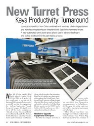
Stand-Alone Punch machine user manual - Finn-Power International ...
Stand-Alone Punch machine user manual - Finn-Power International ...
Stand-Alone Punch machine user manual - Finn-Power International ...

You also want an ePaper? Increase the reach of your titles
YUMPU automatically turns print PDFs into web optimized ePapers that Google loves.
The goal in using a CAM database is to find settings that will work for overall<br />
use for each material type and thickness. For example, a specific material<br />
requires certain size parts to be tabbed into place, you would set the microjoints<br />
to be applied each time for that specific part geometry dimensions. If a<br />
parameter is for a one-time use then when the system asks to save settings click<br />
‘No’.<br />
Again, a suggestion is to first find settings that will work for each material type<br />
and thickness. Once these settings have been established they will not have to<br />
be changed by the <strong>user</strong>, unless for a unique case. The Cam.mdb given with the<br />
<strong>machine</strong> installation is a starter database with default materials loaded within. It<br />
is up to the customer to add new and set parameters for all materials.<br />
4.4.2 Settings<br />
Each individual setting for Autotool dialog can be found in the Appendix D at the<br />
end of this <strong>manual</strong>. There is also more information that can be found in help<br />
documentation by pressing F1 while in NC Express.<br />
4.4.2.1 General Tab<br />
General tab gives the <strong>user</strong> the ability to set all major functions of Autotool,<br />
when Autotool is first opened. Functions Machining mode, tooling (alternative<br />
& where tools are used from), and Sorting applied are found here. DXF file<br />
CAD layers can be filtered from parts here.<br />
4.4.2.2 Destruct Tab<br />
Destruct settings allows <strong>user</strong> to set restrictions on what will be destructed within<br />
a part. Destruct will apply tooling to consume the entire material of either<br />
internal (Destruct) or external contour (Notch). Restrictions are set here which<br />
determine what will be destructed.<br />
4.4.2.3 Microjoint Tab<br />
Microjoints (tabs) are applied when a piece of material will be left within the<br />
sheet or within a part. When a microjoint is applied there is a small gap<br />
between two punch hits or in the corner of a part, allowing the material to stay<br />
in place. Microjoints can be applied to either internal or external contours.<br />
Settings within Autotool allow the <strong>user</strong> to set restrictions on which line<br />
segments will have microjoints applied. The size of the gap (joint width) or<br />
microjoint tools can be used also. All values here can or will change depending<br />
on material type and thickness.<br />
4-44