- Page 1 and 2:
Finn-Power International 710 Reming
- Page 3 and 4:
1 INTRODUCTION ____________________
- Page 5 and 6:
4.6.1.3 DESTRUCT __________________
- Page 7 and 8:
9.1 USE SPLIT-SCREEN PART DIALOG __
- Page 9 and 10:
2 SETTING UP NC EXPRESS The initial
- Page 11 and 12:
2.1.1.1.2 Calculation for Stroke Le
- Page 13 and 14:
o Optimization group- REGULAR o Con
- Page 15 and 16:
NOTE- If the tool’s center point
- Page 17 and 18:
Go to Settings menu | Machine Param
- Page 19 and 20:
2.2.1 Turret(s) within NC Express T
- Page 21 and 22:
2.2.2.1 Station Type Station type w
- Page 23 and 24:
e used to allow the B tool to be pl
- Page 25 and 26:
3 STARTING TO USE NC EXPRESS Starti
- Page 27 and 28:
eing Autotool settings, Nest settin
- Page 29 and 30:
Once a new part has been selected a
- Page 31 and 32:
To save part either go to File menu
- Page 33 and 34:
The duplicate lines were ignored he
- Page 35 and 36:
4.3 CP File (Part File) In NC Expre
- Page 37 and 38:
Note: Allows you to type in informa
- Page 39 and 40:
Step 3: Navigate to a different fol
- Page 41 and 42:
Load Parts- In the case where the P
- Page 43 and 44:
4.4 Automatic Tooling (Autotool) Th
- Page 45 and 46:
4.4.2.4 Settings Tab Settings tab h
- Page 47 and 48:
4.4.5 Presheared Parts (Sized parts
- Page 49 and 50:
Step 5: Click OK when done modifyin
- Page 51 and 52:
Step 5: Click OK to run Autotool. N
- Page 53 and 54:
Step 4: Click Apply then OK. Step 5
- Page 55 and 56:
Example 2 Below shows example of ro
- Page 57 and 58:
Description- important to name taug
- Page 59 and 60:
Go to Tooling menu | select Teach C
- Page 61 and 62:
‘Show the whole tool library’.
- Page 63 and 64:
a. Click outside contour top edge a
- Page 65 and 66:
4. Click Undo, on Nibble dialog, to
- Page 67 and 68:
3. Add tooling to corner notch a. F
- Page 69 and 70:
Clicking will automatically fill i
- Page 71 and 72:
The order of tools was changed to m
- Page 73 and 74:
Rejoin the cycle Step 4: Left click
- Page 75 and 76:
Sheet detection- Enable/Disable she
- Page 77 and 78:
4.6.5.2 Sorting Sorting is used to
- Page 79 and 80:
Database for stored plate informati
- Page 81 and 82:
tools will have restrictions depend
- Page 83 and 84:
5.2.3 Template Turret Template turr
- Page 85 and 86:
to create only one nest pattern. A
- Page 87 and 88:
Step 2: Setup of part. Open Autotoo
- Page 89 and 90:
When parameters are set click OK to
- Page 91 and 92: c. Open the Nest dialog d. Change t
- Page 93 and 94: In general, when utilizing Common L
- Page 95 and 96: 5.9 Modifying Part’s/Tooling (for
- Page 97 and 98: 6 OPTIMIZATION Optimization is the
- Page 99 and 100: When setting the order of the Tool
- Page 101 and 102: Punch Optimizer and can be utilized
- Page 103 and 104: Once the Punching was changed to St
- Page 105 and 106: Interactive Optimizer- Go to Proces
- Page 107 and 108: The final outcome of the nest separ
- Page 109 and 110: 6.4 Retool Nest (Automatic) Within
- Page 111 and 112: Modify automatically optimized plat
- Page 113 and 114: 7 Simulator To review an optimized
- Page 115 and 116: 8 POST PROCESSING (Create NC Code)
- Page 117 and 118: 9 Options and Reports Options, with
- Page 119 and 120: Run Name- Enter a nest number only
- Page 121 and 122: 9.2.3.3 Printing the Report This ca
- Page 123 and 124: o Order: Sort part orders by Order
- Page 125 and 126: o Nested: All the parts are nested.
- Page 127 and 128: NESTPART1.cp Order name: TEST Mac
- Page 129 and 130: 11 Appendix A- Modify tooling Tool
- Page 131 and 132: TYPE PARAMETERS DESCRIPTION BOTTOM_
- Page 133 and 134: Tapping Starting Value Starting lev
- Page 135 and 136: 12 Appendix B- Special tool informa
- Page 137 and 138: • Protection length (C)- Sets len
- Page 139 and 140: 26 0.0179 0.001 0.002 0.003 24 0.02
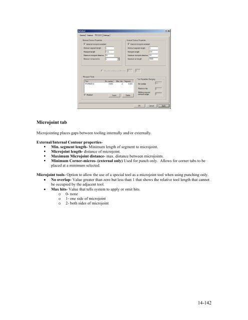
- Page 141: Destruct tab o Sorting device- allo
- Page 145 and 146: Zone Number (Zone) Tool packages (
- Page 147 and 148: 16 Appendix F- Interactive Zones Se