- Page 1 and 2:
SFTOS Configuration Guide Version 2
- Page 3 and 4:
SFTOS 2.5.2 adds: • A substantial
- Page 5 and 6:
Contents New Features . . . . . . .
- Page 7 and 8:
Chapter 3 Management . . . . . . .
- Page 9 and 10:
Chapter 9 Spanning Tree . . . . . .
- Page 11 and 12:
Configuring a Native VLAN . . . . .
- Page 13 and 14:
List of Figures Figure 1 Using the
- Page 15 and 16:
Figure 77 Using the show interface
- Page 17 and 18:
Figure 158 Using the access-list Co
- Page 19:
Figure 243 Configuring VLANs for OS
- Page 22 and 23:
Audience This document is intended
- Page 24 and 25:
Technical Support The iSupport Webs
- Page 26 and 27:
26 About this Guide
- Page 28 and 29:
— Flow Control at the MAC layer:
- Page 30 and 31:
• HTML-based Management • HTTPS
- Page 32 and 33:
(Force10 S50) #show port 1/0/2 Figu
- Page 34 and 35:
34 SFTOS Features
- Page 36 and 37:
Setting up a Management Connection
- Page 38 and 39:
Step Task (continued) 5 Enter Line
- Page 40 and 41:
Getting Help From the CLI The follo
- Page 42 and 43:
Showing Network Settings Execute th
- Page 44 and 45:
Displaying Statistics Privileged Ex
- Page 46 and 47:
Force10 (Config)#users snmpv3 acces
- Page 48 and 49:
Enabling Telnet to the Switch Acces
- Page 50 and 51:
• Enabling Spanning Tree Protocol
- Page 52 and 53:
The S-Series switch contains severa
- Page 54 and 55:
Downloading a Software Image After
- Page 56 and 57:
5. After the transfer is complete,
- Page 58 and 59:
An alternative is to use the copy c
- Page 60 and 61:
Note that the association of a part
- Page 62 and 63:
After installing SFTOS 2.5.1 on the
- Page 64 and 65:
When converting from a Routing imag
- Page 66 and 67:
Saving the Startup Configuration to
- Page 68 and 69:
Chapter 5, Stacking S-Series Switch
- Page 70 and 71:
Uploading a Configuration Script to
- Page 72 and 73:
Troubleshooting a Downloaded Script
- Page 74 and 75:
Listing Configuration Scripts The s
- Page 76 and 77:
Changing the Management VLAN from t
- Page 78 and 79:
Setting the Host Name Prompt If you
- Page 80 and 81:
Setting up SNMP Management Simple N
- Page 82 and 83:
Commands to [disable] enable traps
- Page 84 and 85:
RMON is an extension of SNMP, and r
- Page 86 and 87:
Figure 47 RMON Event Thresholds Fig
- Page 88 and 89:
The software clock runs only when t
- Page 90 and 91:
Example #5: show sntp server Force1
- Page 92 and 93:
• logging history. See Configurin
- Page 94 and 95:
Interpreting system log messages Ta
- Page 96 and 97:
Displaying the SNMP Trap Log The sh
- Page 98 and 99:
Force10 #config Force10 (Config)#lo
- Page 100 and 101:
100 System Logs
- Page 102 and 103:
• The S50N, S50V, and S25P models
- Page 104 and 105:
Management Unit Selection Algorithm
- Page 106 and 107:
All of the forwarding protocols run
- Page 108 and 109:
Use the member unit switchindex com
- Page 110 and 111:
Setting Management Unit Preferences
- Page 112 and 113:
Hardware Management Preference The
- Page 114 and 115:
Notice, in Figure 67, that show swi
- Page 116 and 117:
Using show Commands for Stacking In
- Page 118 and 119:
The show stack command shows pretty
- Page 120 and 121:
Table 3 Interfaces in the S-Series
- Page 122 and 123:
Force10 #show interface 1/0/1 Ports
- Page 124 and 125:
Use the show interface ethernet uni
- Page 126 and 127:
Physical interfaces can become part
- Page 128 and 129:
Enabling an Interface Ports are shu
- Page 130 and 131:
The following table describes the e
- Page 132 and 133:
If you connect powered devices to a
- Page 134 and 135:
Bulk Configuration Bulk configurati
- Page 136 and 137:
136 Configuring Interfaces
- Page 138 and 139:
Table 6 describes the messages that
- Page 140 and 141:
Verifying the DHCP Server Configura
- Page 142 and 143:
Configuration Example — DHCP Serv
- Page 144 and 145:
Step Command Syntax 2 authenticatio
- Page 146 and 147:
Command Syntax Command Mode Purpose
- Page 148 and 149:
Force10 #config Force10 (Config)# F
- Page 150 and 151:
The scripts provided use OpenSSH (h
- Page 152 and 153:
3. Use the show logging command to
- Page 154 and 155:
Spanning Tree Protocol (STP, IEEE 8
- Page 156 and 157:
Port States RSTP merges states from
- Page 158 and 159:
MSTP CLI Management SFTOS supports
- Page 160 and 161:
Enabling STP Use the following comm
- Page 162 and 163:
The following commands influence wh
- Page 164 and 165:
MSTP Configuration Example The foll
- Page 166 and 167:
Use the show spanning-tree interfac
- Page 168 and 169:
Figure 119 displays the output from
- Page 170 and 171:
Figure 123 shows the output of the
- Page 172 and 173:
172 Spanning Tree
- Page 174 and 175:
• Static configuration is used wh
- Page 176 and 177:
Link Aggregation Group (LAG) Comman
- Page 178 and 179:
Interface Config mode commands Note
- Page 180 and 181:
Basic LAG configuration example Thi
- Page 182 and 183:
Using the Interface Range mode If y
- Page 184 and 185:
Verify the status of the LAG as dyn
- Page 186 and 187:
• Edge device: An edge device han
- Page 188 and 189:
Deploying DiffServ The four basic s
- Page 190 and 191:
Creating a Policy-Map The second st
- Page 192 and 193:
Example (per interface): Force10 #c
- Page 194 and 195:
Force10 #show class-map Class Class
- Page 196 and 197:
Conform Secondary CoS—The action
- Page 198 and 199:
The following is sample output from
- Page 200 and 201:
VLAN 10: Finance Layer 3 Switch Por
- Page 202 and 203:
Configuring Differentiated Services
- Page 204 and 205:
204 Quality of Service
- Page 206 and 207:
Note that the order of the rules is
- Page 208 and 209:
— show mac access-lists Force10 #
- Page 210 and 211:
Protecting the Management Interface
- Page 212 and 213:
• An ACL applied to loopback inte
- Page 214 and 215:
Use the show storm-control command
- Page 216 and 217:
A VLAN is a set of end stations and
- Page 218 and 219:
Executing the interface vlan 2-4094
- Page 220 and 221:
Example of creating a VLAN and assi
- Page 222 and 223:
3. Create VLAN 4 on switch R3 and a
- Page 224 and 225: Example of adding a LAG to a VLAN F
- Page 226 and 227: Example of creating a routed VLAN o
- Page 228 and 229: GARP Timers The following are GARP
- Page 230 and 231: 1. Name switch R1, enable GVRP glob
- Page 232 and 233: Configuring a Private Edge VLAN (PV
- Page 234 and 235: Two commands can configure a native
- Page 236 and 237: Figure 186 Validating a Tagged Inte
- Page 238 and 239: . Force10 #show interface ethernet
- Page 240 and 241: DVLAN configuration example The exa
- Page 242 and 243: Configure switch R7: !---------Trun
- Page 244 and 245: Using the show vlan id vlan-id comm
- Page 246 and 247: set igmp maxresponse 1-3599 (typica
- Page 248 and 249: Use the show ip igmp interface unit
- Page 250 and 251: Port Mirroring Commands The followi
- Page 252 and 253: Stopping the mirroring session and
- Page 254 and 255: 254 Port Mirroring
- Page 256 and 257: Enabling Routing The S-Series alway
- Page 258 and 259: Port Routing Configuration Example
- Page 260 and 261: IGMP Proxy Configuration The follow
- Page 262 and 263: Verifying the configuration Verify
- Page 264 and 265: RIP Configuration Example The confi
- Page 266 and 267: Border Router Port 0/2 192.150.2.1
- Page 268 and 269: Configuring OSPF on an S-Series ope
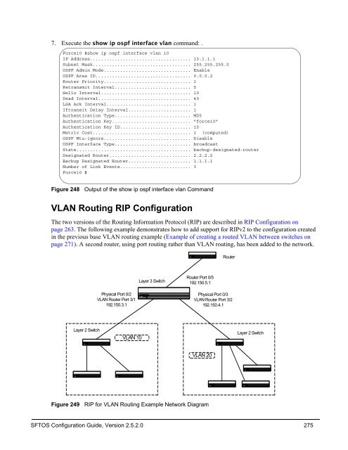
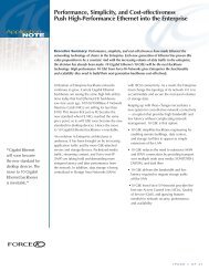
- Page 270 and 271: VLAN Routing This section introduce
- Page 272 and 273: 3. As above, enable routing on R2:
- Page 276 and 277: 1. As done previously, create the V
- Page 278 and 279: 3. Use the show vlan id, show ip in
- Page 280 and 281: Port 0/2 192.150.2.1/24 Virtual Rou
- Page 282 and 283: 3. Configure the IP address and sub
- Page 284 and 285: Note: In SFTOS 2.3.1.9, these messa
- Page 286 and 287: In addition to issuing the show swi
- Page 288 and 289: Monitoring SFPs The four fiber port
- Page 290 and 291: packets can be routed by the hardwa
- Page 292 and 293: • What was the LED status? (If th
- Page 294 and 295: 294 • GVRP — Dynamic VLAN Regis
- Page 296 and 297: 296 QoS • RFC 2474 — Definition
- Page 298 and 299: MIBs 298 • RFC 2096: IP forwardin
- Page 300 and 301: 300 Force 10 MIBs You can see this
- Page 302 and 303: 302
- Page 304 and 305: configuration, restore to factory d
- Page 306 and 307: inlinepower threshold command 132 i
- Page 308 and 309: MIBs, supported industry 298 mirror
- Page 310 and 311: RFC 3768 279 RFC 768 28, 294 RFC 78
- Page 312 and 313: show stack-port command 103 show st
- Page 314: VoIP support 202 VRID 281 VRRP 279