Blind actuator 1-gang flush-mounted Order-No. 2165 00 - Gira
Blind actuator 1-gang flush-mounted Order-No. 2165 00 - Gira
Blind actuator 1-gang flush-mounted Order-No. 2165 00 - Gira

Create successful ePaper yourself
Turn your PDF publications into a flip-book with our unique Google optimized e-Paper software.
Software "Venetian blind, input 20BD11"<br />
Functional description<br />
4.2.4 Functional description<br />
4.2.4.1 General functions for extension inputs<br />
Effect of the extension inputs<br />
The device possesses extension inputs, which can have an internal effect on the Venetian blind<br />
output or, alternatively, affect the KNX/EIB separately, depending on the ETS configuration.<br />
With the internal effect, inputs 1 and 2 directly operate the Venetian blind output. This<br />
configuration also corresponds to the as-delivered status (unprogrammed device). In this way, it<br />
is possible, for example, for a connected Venetian blind 'on the building site' to be<br />
commissioned and operated simply by applying the bus voltage and without using additional<br />
sensors.<br />
With the effect on the bus, the inputs can, independently of one another, transmit telegrams for<br />
switching or dimming for Venetian blind control or value encoder use (dimming value encoder,<br />
light scene extension). They then function like a pushbutton interface.<br />
The parameter "Effect of the extension inputs" on the "General" parameter page defines the use<br />
of the inputs.<br />
o Set the parameter to "I1 & I2 internally on O1, I3 separately on the bus".<br />
The extension inputs 1 and 2 only directly affect the internal Venetian blind output of the<br />
device. For two-area operation, input 1 operates the "UP" command and input 2 the<br />
"DOWN" command. Input 3 behaves independently and, through separate communication<br />
objects, only affects the bus.<br />
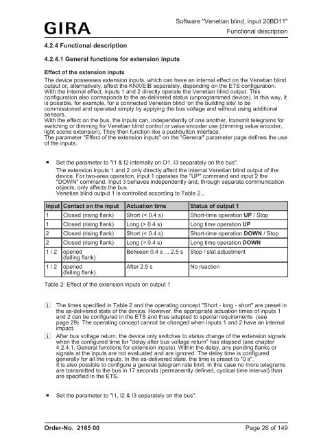
Venetian blind output 1 is controlled according to Table 2...<br />
Input Contact on the input Actuation time Status of output 1<br />
1 Closed (rising flank) Short (< 0.4 s) Short-time operation UP / Stop<br />
1 Closed (rising flank) Long (> 0.4 s) Long time operation UP<br />
2 Closed (rising flank) Short (< 0.4 s) Short-time operation DOWN / Stop<br />
2 Closed (rising flank) Long (> 0.4 s) Long time operation DOWN<br />
1 / 2 opened<br />
(falling flank)<br />
1 / 2 opened<br />
(falling flank)<br />
Between 0.4 s ... 2.5 s<br />
After 2.5 s<br />
Table 2: Effect of the extension inputs on output 1<br />
Stop / slat adjustment<br />
<strong>No</strong> reaction<br />
i The times specified in Table 2 and the operating concept "Short - long - short" are preset in<br />
the as-delivered state of the device. However, the appropriate actuation times of inputs 1<br />
and 2 can be configured in the ETS and thus adapted to special requirements (see<br />
page 29). The operating concept cannot be changed when inputs 1 and 2 have an internal<br />
impact.<br />
i After bus voltage return, the device only switches to status change of the extension signals<br />
when the configured time for "delay after bus voltage return" has elapsed (see chapter<br />
4.2.4.1. General functions for extension inputs). Within the delay, any pending flanks or<br />
signals at the inputs are not evaluated and are ignored. The delay time is configured<br />
generally for all the inputs. In the as-delivered state, the time is preset to "0 s".<br />
It is also possible to configure a general telegram rate limit. In this case no more telegrams<br />
are transmitted to the bus in 17 seconds (permanently defined, cyclical time interval) than<br />
are specified in the ETS.<br />
o Set the parameter to "I1, I2 & I3 separately on the bus".<br />
<strong>Order</strong>-<strong>No</strong>. <strong>2165</strong> <strong>00</strong><br />
Page 26 of 149