Blind actuator 1-gang flush-mounted Order-No. 2165 00 - Gira
Blind actuator 1-gang flush-mounted Order-No. 2165 00 - Gira
Blind actuator 1-gang flush-mounted Order-No. 2165 00 - Gira

You also want an ePaper? Increase the reach of your titles
YUMPU automatically turns print PDFs into web optimized ePapers that Google loves.
KNX/EIB<br />
Product documentation<br />
Issue:<br />
13.02.2012<br />
63920221<br />
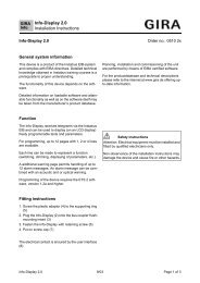
<strong>Blind</strong> <strong>actuator</strong> 1-<strong>gang</strong> <strong>flush</strong>-<strong>mounted</strong><br />
<strong>Order</strong>-<strong>No</strong>. <strong>2165</strong> <strong>00</strong>
KNX/EIB<br />
Product documentation<br />
Contents<br />
1 Product definition ................................................................................................................ 3<br />
1.1 Product catalogue ........................................................................................................... 3<br />
1.2 Function .......................................................................................................................... 3<br />
2 Installation, electrical connection and operation ............................................................. 4<br />
2.1 Safety instructions .......................................................................................................... 4<br />
2.2 Device components ........................................................................................................ 5<br />
2.3 Fitting and electrical connection ..................................................................................... 6<br />
2.4 Commissioning ............................................................................................................... 9<br />
2.5 Operation ...................................................................................................................... 12<br />
3 Technical data .................................................................................................................... 13<br />
4 Software description ......................................................................................................... 14<br />
4.1 Software specification ................................................................................................... 14<br />
4.2 Software "Venetian blind, input 20BD11" ..................................................................... 15<br />
4.2.1 Scope of functions ................................................................................................. 15<br />
4.2.2 Software information ............................................................................................. 17<br />
4.2.3 Object table ........................................................................................................... 18<br />
4.2.3.1 Extension input objects .................................................................................. 18<br />
4.2.3.2 Venetian blind output objects ......................................................................... 21<br />
4.2.4 Functional description ........................................................................................... 26<br />
4.2.4.1 General functions for extension inputs .......................................................... 26<br />
4.2.4.2 General functions for the Venetian blind output ............................................. 28<br />
4.2.4.3 Channel-orientated functions for extension inputs ......................................... 29<br />
4.2.4.3.1 Function configuration of the extension inputs ....................................... 29<br />
4.2.4.3.2 Disabling function for extension inputs ................................................... 36<br />
4.2.4.4 Channel-oriented functions for the Venetian blind output .............................. 37<br />
4.2.4.4.1 General settings ..................................................................................... 37<br />
4.2.4.4.2 Movement time settings ......................................................................... 40<br />
4.2.4.4.3 Positioning and feedback settings .......................................................... 44<br />
4.2.4.4.4 Safety function settings .......................................................................... 54<br />
4.2.4.4.5 Sun protection settings ........................................................................... 58<br />
4.2.4.4.6 Settings for automatic heating/cooling ................................................... 83<br />
4.2.4.4.7 Scene function settings ......................................................................... 89<br />
4.2.4.4.8 Forced position settings ......................................................................... 92<br />
4.2.4.4.9 Fabric stretching settings ....................................................................... 95<br />
4.2.4.5 Priorities for the output ................................................................................... 97<br />
4.2.5 Delivery state ........................................................................................................ 98<br />
4.2.6 Parameters ............................................................................................................ 99<br />
4.2.6.1 General parameters ....................................................................................... 99<br />
4.2.6.2 Parameters for the extension inputs ............................................................ 101<br />
4.2.6.3 Parameters for the Venetian blind output .................................................... 114<br />
5 Appendix ........................................................................................................................... 148<br />
5.1 Index ........................................................................................................................... 148<br />
<strong>Order</strong>-<strong>No</strong>. <strong>2165</strong> <strong>00</strong><br />
Page 2 of 149
Product definition<br />
1 Product definition<br />
1.1 Product catalogue<br />
Product name: <strong>Blind</strong> <strong>actuator</strong> 1-<strong>gang</strong> <strong>flush</strong>-<strong>mounted</strong><br />
Use:<br />
Form:<br />
Actuator / sensor<br />
UP (concealed)<br />
<strong>Order</strong>-<strong>No</strong>. <strong>2165</strong> <strong>00</strong><br />
1.2 Function<br />
The output (O1) allows the control of electrically-operated Venetian blinds, roller shutters,<br />
awnings, venting louvers or similar blinds for 230 V AC mains voltage. The relay contacts for the<br />
movement directions (up, down) are bistable, meaning that the last switching status set also<br />
remains intact, should the mains voltage fail.<br />
The functionalities that can be preset with the ETS for the Venetian blind output include, for<br />
instance, separately configurable travelling times, enlarged feedback functions, assignment to<br />
up to 5 different safety functions, an extensive sun protection function, and incorporation into<br />
scenes or forced-position applications.<br />
Besides the output, the device possesses three additional inputs, which can have an internal<br />
effect on the Venetian blind output or, alternatively, affect the KNX/EIB separately, depending<br />
on the ETS configuration. The connected potential-free switch or button contacts are<br />
downloaded to the device via a shared reference potential. With the internal effect, inputs 1 and<br />
2 directly operate the Venetian blind output. With the effect on the bus, the inputs can,<br />
independently of one another, transmit telegrams for switching or dimming for Venetian blind<br />
control or value encoder use (dimming value encoder, light scene extension).<br />
The connection of 230 V signals or other external voltages to the extension inputs is not<br />
permitted!<br />
For configuration and commissioning of this device, it is necessary to use ETS3.0 from version<br />
"d" onwards. Advantages with regard to downloading (significantly shorter loading times) and<br />
parameter programming can be expected only if this ETS patch version or later versions are<br />
used.<br />
The device electronics are supplied exclusively from the bus voltage. The device is designed for<br />
installation in concealed switch or device boxes in permanent installations.<br />
<strong>Order</strong>-<strong>No</strong>. <strong>2165</strong> <strong>00</strong><br />
Page 3 of 149
2 Installation, electrical connection and operation<br />
2.1 Safety instructions<br />
Electrical equipment may only be installed and fitted by electrically skilled persons. The<br />
applicable accident prevention regulations must be observed.<br />
Failure to observe the instructions may cause damage to the device and result in fire and<br />
other hazards.<br />
Before working on the device or exchanging the connected loads, disconnect it from the<br />
power supply (switch off the miniature circuit breaker), otherwise there is the risk of an<br />
electric shock.<br />
The device is not suitable for disconnection from supply voltage.<br />
Make sure during the installation that there is always sufficient insulation between the<br />
mains voltage and the bus and extension inputs. A minimum distance of at least 4 mm<br />
must be maintained between bus/extensions and mains voltage cores.<br />
Do not connect any external voltage to the inputs, since doing so may damage the<br />
device(s), and the SELV potential on the KNX bus line will no longer be available.<br />
For parallel connection of several drives to a shutter / blind output it is indispensable to<br />
observe the corresponding instructions of the manufacturers, and to use a cutoff relay if<br />
necessary. There is otherwise risk of irreparable damage to the drives.<br />
Use only curtains with mechanical or electronic limit switches. Check the limit switches<br />
for correct adjustment.<br />
Do not connect any three-phase motors.<br />
Installation, electrical connection and operation<br />
The device may not be opened or operated outside the technical specifications.<br />
<strong>Order</strong>-<strong>No</strong>. <strong>2165</strong> <strong>00</strong><br />
Page 4 of 149
Installation, electrical connection and operation<br />
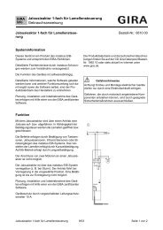
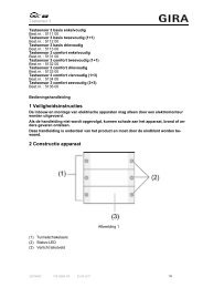
2.2 Device components<br />
Figure 1: Device components<br />
(1) Control cable (bus connection and extension inputs)<br />
(2) Programming button and programming LED (red).<br />
(3) Connection cables for mains voltage and load (please pay close attention to the housing<br />
connection labelling)<br />
Connection assignment of the control cable (1)<br />
RD (red): KNX bus voltage +<br />
BK (black): KNX bus voltage -<br />
GN (green): Input 1<br />
YE (yellow): Input 2<br />
WH (white): Input 3<br />
BN (brown): Reference potential "COM" for inputs 1...3<br />
Connection assignment for mains voltage and load (3)<br />
BK (black): Mains voltage (L)<br />
BN (brown): Connection for Venetian blind drive (UP, n) - relay output<br />
PK (pink): Connection for Venetian blind drive (DOWN, o) - relay output<br />
i The sequence of the connections on the device for mains voltage (L) and load (o)<br />
depends upon the device version. The device versions can be recognised by the different<br />
connection labelling in the housing print images. Furthermore, a version identification in<br />
text form is added in the print images. The electrical connection must be carried out in<br />
accordance with the connection diagrams (see page 6).<br />
<strong>Order</strong>-<strong>No</strong>. <strong>2165</strong> <strong>00</strong><br />
Page 5 of 149
2.3 Fitting and electrical connection<br />
Installation, electrical connection and operation<br />
DANGER!<br />
Electrical shock when live parts are touched.<br />
Electrical shocks can be fatal.<br />
Before working on the device, disconnect the power supply and cover up live<br />
parts in the working environment.<br />
DANGER!<br />
When connecting the bus/extensions and mains voltage wires in a shared<br />
appliance box, the KNX bus line may come into contact with the mains voltage.<br />
This endangers the safety of the entire KNX installation. People at remote<br />
devices may also receive an electric shock.<br />
Do not place bus/extensions and mains voltage terminals in a shared<br />
connection compartment. Use an appliance box with a fixed partition wall or<br />
separate boxes.<br />
Connecting and fitting the device<br />
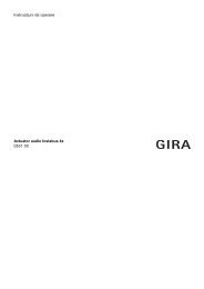
Minimum spacing between the mains voltage and bus/extension wires: 4 mm (Figure 2).<br />
Recommendation: Use an electronics box when installing the device, e.g. with a series switch<br />
(Figure 3).<br />
Figure 2: Minimum cable spacing<br />
<strong>Order</strong>-<strong>No</strong>. <strong>2165</strong> <strong>00</strong><br />
Page 6 of 149
Installation, electrical connection and operation<br />
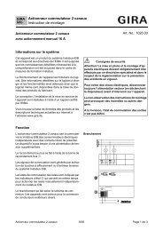
Figure 3: Installing the device in an electronics box (example)<br />
(4) Device box (e.g. electronics box)<br />
(5) Partition<br />
(6) Series switch<br />
(7) Potential-free contact, e. g. window contact<br />
o Connect the mains voltage and the Venetian blind drive using the included screwless<br />
terminals. Connect the mains voltage and load in accordance with the labelling on the<br />
housing print image (Figure 4)!<br />
Figure 4: Connection of the mains voltage and the load (depending upon the version labelling)<br />
<strong>Order</strong>-<strong>No</strong>. <strong>2165</strong> <strong>00</strong><br />
Page 7 of 149
Installation, electrical connection and operation<br />
i The sequence of the connections on the device for mains voltage (L) and load (o)<br />
depends upon the device version. The device versions can be recognised by the different<br />
connection labelling in the housing print images. Furthermore, a version identification in<br />
text form is added in the print images.<br />
Devices with no version labelling or with the labelling "V02" must be connected in<br />
accordance with connection diagram A. Devices with the version labelling "V01" must be<br />
connected in accordance with connection diagram B.<br />
The colour assignment of the connecting wires is the same for both device versions.<br />
o Connect the device to KNX. For this, use a KNX connection terminal.<br />
o If necessary, connect potential-free contacts to the inputs (Figure 5).<br />
i Use suitable terminals to connect potential-free contacts to the control cable.<br />
i The reference potential "com" may only be switched together with the reference potentials<br />
of other devices of the same type (!).<br />
Figure 5: Connection of the extension inputs<br />
o Install the device in a <strong>flush</strong>-<strong>mounted</strong> box.<br />
i Venting louvres must be connected in such a way that they open in travel direction "UP -<br />
n" and close in travel direction "DOWN – o".<br />
i Do not connect any three-phase motors.<br />
i Insulate unused wires of the 6-pin control cable against each other and outside voltage.<br />
i To avoid interference from EMC radiation, the cables of the extension inputs should not be<br />
run in parallel to cables carrying voltage.<br />
<strong>Order</strong>-<strong>No</strong>. <strong>2165</strong> <strong>00</strong><br />
Page 8 of 149
Installation, electrical connection and operation<br />
2.4 Commissioning<br />
After installation and connection of the bus line, the mains voltage and of all electrical loads, the<br />
device can be put into operation. For output 1 only, special commissioning steps have to be<br />
performed prior to programming with the ETS. The following procedure is generally<br />
recommended...<br />
DANGER!<br />
Electrical shock on contact with live parts in the installation environment.<br />
Electrical shocks can be fatal.<br />
Before working on the device, disconnect the power supply and cover up live<br />
parts in the working environment.<br />
Measuring the travelling times<br />
For the purpose of positioning blinds, shutters and awnings or for adjusting the opening angle of<br />
venting louvers, the device needs accurate information about the maximum travelling time for<br />
output 1.<br />
The bus and mains voltage must be switched on.<br />
Recommendation: Device operation using extension inputs (internal effect of input 1 "UP" and 2<br />
"DOWN" on output 1 = as-delivered state).<br />
o If not yet done, move the blind/shutter into the upper end position (open venting louver<br />
completely).<br />
The upper limit-stop position is reached (venting louver opened).<br />
o Start the measuring time and move the blind/shutter by control into the lower end position<br />
(close the venting louver completely).<br />
o Stop the time measurement when the lower limit (when the completely closed) position is<br />
reached.<br />
o Enter the measured value in the ETS (cf. "software description").<br />
i It is wise to perform several time measurements and to take the average of these values.<br />
i The travelling time can also be determined after commissioning with the ETS (bus<br />
operation through communication objects).<br />
Measuring the travelling time extension<br />
When travelling upwards, blinds or shutters have a tendency of moving more slowly due to their<br />
own weight or to external physical influences (e.g. temperature, wind, etc.). The same applies to<br />
venting louvers where opening may take longer than closing.<br />
For this reason, the device takes the configured travelling time extension into account for output<br />
1 when moving upwards or when opening the louvers (MOVE operation / positioning). The<br />
extension is computed as a percentage of the difference of the travelling times in both<br />
directions.<br />
The bus and mains voltage must be switched on.<br />
Recommendation: Device operation using extension inputs (internal effect of input 1 "UP" and 2<br />
"DOWN" on output 1 = as-delivered state).<br />
The blind/shutter (venting louver) must be in the lower end position (venting louver closed).<br />
o If not yet done, move the blind/shutter into the lower end position (close venting louver<br />
completely)<br />
Lower end position reached (venting louver closed).<br />
o Start the measuring time and move the blind/shutter by control into the upper end position<br />
(open the venting louver completely).<br />
o Stop the time measurement when the upper limit (the completely open) position is reached.<br />
o Express the measured value as a percentage of the determined blind/shutter travelling time<br />
and enter the value in the ETS (cf. software description).<br />
i It is wise to perform several time measurements and to take the average of these values.<br />
<strong>Order</strong>-<strong>No</strong>. <strong>2165</strong> <strong>00</strong><br />
Page 9 of 149
Installation, electrical connection and operation<br />
i The travelling time extension can also be determined after commissioning with the ETS<br />
(bus operation through communication objects).<br />
Measuring the slat moving time (only for blinds)<br />
In the case of blinds with slats, the slat moving time is for technical reasons part of the overall<br />
travelling time of the blind. The slat moving time is the time required for a movement between<br />
the slat positions "closed – 1<strong>00</strong> %" and "open – 0 %". In order to compute the opening angle of<br />
the slats, the device needs an information about the slat moving time.<br />
The slats must be completely closed (as in case of downward travel of the blind).<br />
The bus and mains voltage must be switched on.<br />
Recommendation: Device operation using extension inputs (internal effect of input 1 "UP" and 2<br />
"DOWN" on output 1 = as-delivered state).<br />
o Start the measuring time and open the slats completely by manual control (as in case of<br />
upward travel of the blind).<br />
o Take the measuring time when the completely open position is reached.<br />
o Enter the measured value in the ETS (cf. "software description").<br />
i It is wise to perform several time measurements and to take the average of these values.<br />
i The slat moving time can also be determined after commissioning with the ETS (bus<br />
operation through communication objects).<br />
Commissioning with the ETS<br />
After measuring the times for output 1, the device can be programmed by the ETS.<br />
Commissioning is basically confined to programming of the physical address and the application<br />
data with the ETS.<br />
Project planning and commissioning of the device using the ETS 3.0d with Patch A or newer<br />
versions.<br />
The device is connected and ready for operation.<br />
o Switch on the bus voltage<br />
Check: When the programming button is pressed, the red programming LED must light up.<br />
Switching on the bus voltage causes the device carry out the "Behaviour after bus voltage<br />
return" configured in the ETS. In the state as supplied, this behaviour is set as follows for<br />
the outputs...<br />
<strong>Blind</strong> output (O1): Drive stop,<br />
O2 (valve output): Close valve. (Valve direction of action: deenergised closed = output<br />
OFF).<br />
o Programming the physical address and the application data with the ETS.<br />
Performing a reference movement (optional)<br />
The device can approach newly preset curtain or louver positions for output 1 only if the current<br />
positions are known. For this purpose, the output must be given the opportunity to synchronise<br />
itself whenever the bus voltage is switched on or after every ETS programming run (physical<br />
address, application program, partial download). This synchronisation is performed by means of<br />
the reference movement.<br />
The bus and mains voltage must be switched on.<br />
o If not yet done, move the curtains to the upper end position (open venting louver<br />
completely).<br />
o Wait until the output relay has switched off (not only the limit switch of the drive).<br />
The reference movement is terminated.<br />
<strong>Order</strong>-<strong>No</strong>. <strong>2165</strong> <strong>00</strong><br />
Page 10 of 149
Installation, electrical connection and operation<br />
i This device stores the curtain, slat or louver positions temporarily. After each bus voltage<br />
failure or after programming with the ETS, the device therefore automatically performs a<br />
reference movement for output 1 before a new position can be approached.<br />
i After bus voltage return, the device generates an "invalid position" message for output 1<br />
which can also be transmitted to the bus, if so configured. The message is withdrawn<br />
(inverted signal value) as soon as a reference movement could be executed.<br />
<strong>Order</strong>-<strong>No</strong>. <strong>2165</strong> <strong>00</strong><br />
Page 11 of 149
Installation, electrical connection and operation<br />
2.5 Operation<br />
In the as-delivered state of the device, extension inputs 1 and 2 have a direct effect on Venetian<br />
blind output 1. In this way, it is possible, for example, for a connected Venetian blind 'on the<br />
building site' to be commissioned and operated simply by applying the bus voltage and without<br />
using additional sensors.<br />
After commissioning using the ETS, extension inputs 1 and 2 behaviour as they are configured<br />
in the ETS. It is also possible to let the inputs internally effect output 1. Alternatively, these<br />
inputs can also affect the bus and control other <strong>actuator</strong>s. The extension inputs then function<br />
like standard KNX/EIB pushbutton interfaces.<br />
i Extension input 3 always behaves independently and, through separate communication<br />
objects, only affects the bus. In the as-delivered state, this extension input is inactive.<br />
If inputs 1 and 2 have an internal effect on output 1, control takes place using the two-area<br />
principle: Input 1 controls the "UP" command and input 2 controls the "DOWN" command.<br />
Venetian blind 1 is controlled according to Table 1...<br />
Input Contact on the input Actuation time Status of output 1<br />
1 Closed (rising flank) Short (< 0.4 s) Short-time operation UP / Stop<br />
1 Closed (rising flank) Long (> 0.4 s) Long time operation UP<br />
2 Closed (rising flank) Short (< 0.4 s) Short-time operation DOWN / Stop<br />
2 Closed (rising flank) Long (> 0.4 s) Long time operation DOWN<br />
1 / 2 opened<br />
(falling flank)<br />
1 / 2 opened<br />
(falling flank)<br />
Between 0.4 s ... 2.5 s<br />
After 2.5 s<br />
Table 1: Effect of the extension inputs on output 1<br />
Stop / slat adjustment<br />
<strong>No</strong> reaction<br />
i The times specified in Table 1 and the operating concept "Short - long - short" are preset in<br />
the as-delivered state of the device. However, the appropriate actuation times of inputs 1<br />
and 2 can be configured in the ETS and thus adapted to special requirements (see<br />
page 29). The operating concept cannot be changed when inputs 1 and 2 have an internal<br />
impact.<br />
i After bus voltage return, the device only switches to status change of the extension signals<br />
when the configured time for "delay after bus voltage return" has elapsed (see chapter<br />
4.2.4.1. General functions for extension inputs). Within the delay, any pending flanks or<br />
signals at the inputs are not evaluated and are ignored. The delay time is configured<br />
generally for all the inputs. In the as-delivered state, the time is preset to "0 s".<br />
<strong>Order</strong>-<strong>No</strong>. <strong>2165</strong> <strong>00</strong><br />
Page 12 of 149
Technical data<br />
3 Technical data<br />
General<br />
Mark of approval<br />
KNX / EIB<br />
Ambient temperature -5 ... +45 °C<br />
Storage/transport temperature -25 ... +70 °C<br />
Dimensions Ø×H<br />
53×28 mm<br />
KNX/EIB supply<br />
KNX medium TP 1<br />
Commissioning mode<br />
S-mode<br />
Rated voltage KNX<br />
DC 21 ... 32 V SELV<br />
Power consumption KNX<br />
max. 240 mW<br />
Connection mode KNX<br />
Connection terminal on control cable<br />
Connection for mains voltage (L)<br />
Connection mode<br />
Terminal (enclosed)<br />
Single stranded<br />
1.0 ... 2.5 mm²<br />
Rated voltage AC 110 ... 240 V ~<br />
Mains frequency<br />
50 / 60 Hz<br />
Output 1 (Venetian blind up / down)<br />
Connection mode<br />
Terminal (enclosed)<br />
Single stranded<br />
1.0 ... 2.5 mm²<br />
Contact type µ<br />
Switching voltage AC 250 V ~<br />
Switching current AC1<br />
3 A<br />
Switch-on current 2<strong>00</strong> µs<br />
max. 90 A<br />
Switch-on current<br />
max. 80 A (1 ms)<br />
Minimum switching current AC<br />
1<strong>00</strong> mA<br />
Motors 230 V<br />
6<strong>00</strong> VA<br />
Motors 110 V<br />
3<strong>00</strong> VA<br />
Inputs (I1, I2, I3)<br />
Input type<br />
Control cable (preterminated)<br />
Total length of extension unit cable<br />
Loop resistance<br />
Potential-free<br />
YY6x0.6<br />
max. 5 m<br />
max. 5<strong>00</strong> Ω<br />
<strong>Order</strong>-<strong>No</strong>. <strong>2165</strong> <strong>00</strong><br />
Page 13 of 149
Software specification<br />
4 Software description<br />
4.1 Software specification<br />
ETS search paths:<br />
shutter / shutter / <strong>Blind</strong> <strong>actuator</strong> 1-<strong>gang</strong> <strong>flush</strong>-<strong>mounted</strong><br />
BAU used: ASIC FZE 1066 + µC<br />
KNX/EIB type class: Device with cert. Physical layer + stack<br />
Configuration:<br />
S-mode standard<br />
PEI type:<br />
"<strong>00</strong>" Hex / "0" Dec<br />
PEI connector:<br />
<strong>No</strong> connector<br />
Application programs:<br />
<strong>No</strong>. Short description Name Version from mask<br />
version<br />
1 Multifunctional shutter/blind application.<br />
Additional comprehensive extension<br />
function.<br />
Venetian blind, input<br />
20BD11<br />
1.1<br />
for ETS3.0d<br />
onwards<br />
705<br />
<strong>Order</strong>-<strong>No</strong>. <strong>2165</strong> <strong>00</strong><br />
Page 14 of 149
4.2 Software "Venetian blind, input 20BD11"<br />
4.2.1 Scope of functions<br />
Software "Venetian blind, input 20BD11"<br />
Scope of functions<br />
General<br />
- 1 x relay output (O1) to control a Venetian blind, roller shutter, awning or venting louver<br />
(mechanical locking of the running directions).<br />
- 3 x extension inputs for potential-free contacts.<br />
- <strong>No</strong> additional power supply required. The device electronics are supplied fully from the bus<br />
line.<br />
- Actively transmitting feedback or status messages of the output can be delayed globally<br />
after bus voltage return or after ETS programming.<br />
- The delay after bus voltage return can also be set generally for the inputs.<br />
- Effect of the extension inputs can be configured: either internal effect of I1 and I2 on the<br />
Venetian blind output (O1) and I3 on the bus or, alternatively, all three inputs separately on<br />
the bus.<br />
- Debounce time and telegram rate limit can be configured for the extension inputs.<br />
<strong>Blind</strong> output (O1)<br />
- Operating mode configurable: control of blinds with slats, shutters, awnings or venting<br />
louvers.<br />
- Separately configurable blind travelling times with travelling time extension for moves into<br />
the upper end position.<br />
- For blinds with slats, a slat moving time can be independently configured<br />
- Travel direction change-over time and the times for short and long-time operation (Step,<br />
Move) presettable.<br />
- <strong>Blind</strong> or slat position feedback telegram. In addition, an invalid blind position or an invalid<br />
travel movement can be reported back. Active (transmitting after changes or cyclically to<br />
the bus) or passive (object readout) feedback functions.<br />
- Assigning of outputs to up to 5 different safety functions (3 wind alarms, 1 rain alarm, 1<br />
frost alarm) optionally with cyclical monitoring.<br />
- An extensive sun protection function with fixed and variable blind or slat positions at the<br />
beginning and at the end of the function can be activated separately for each output.<br />
Dynamic slat offset for slatted blinds included. Also with extended sun protection feature for<br />
integration into sophisticated shading control programs (operated via separate automatic<br />
and disabling object). Optionally also with automatic heating/cooling and presence<br />
detection function.<br />
- Forced position function can be implemented.<br />
- Up to 8 internal scenes configurable.<br />
Extension inputs (I1, I2, I3)<br />
- With separate impact on bus:<br />
Free allocation of the functions switching, dimming, Venetian blind and value encoder.<br />
- Disable object for disabling individual inputs (polarity of the disable object is adjustable).<br />
- Behaviour on bus voltage return can be configured separately for each input.<br />
- Scope of detail for the "Switching" function:<br />
Two independent switching objects available for each input (switching commands can be<br />
configured individually).<br />
Command can be set independently for rising and falling flank (ON, OFF, TOGGLE, no<br />
reaction).<br />
Independent cylical transmission of the switching objects can be selected depending on the<br />
flank or depending on the object value.<br />
- Scope of detail for the "Dimming" function:<br />
Single-surface and double-surface operation possible.<br />
Time between dimming and switching and dimming increments is adjustable.<br />
Telegram repetition and stop telegram transmission possible.<br />
<strong>Order</strong>-<strong>No</strong>. <strong>2165</strong> <strong>00</strong><br />
Page 15 of 149
Software "Venetian blind, input 20BD11"<br />
Scope of functions<br />
- Scope of detail for the "Venetian blind" function:<br />
Command can be set independently for rising flank (no function, UP, DOWN, TOGGLE).<br />
Operation concept configurable (short – long – short or long – short).<br />
Time adjustable between short-time and long-time operation (only for short – long – short)<br />
Adjustable slat adjustment time (time during which a MOVE command can be terminated<br />
by releasing a pushbutton on the input).<br />
- Scope of detail for the "Value encoder" function:<br />
Flank (pushbutton as NO contact, pushbutton as NC contact, switch) and value for flank<br />
can be configured.<br />
Value adjustment for pushbutton long key-press possible for value encoder.<br />
For light scene extension with memory function, the scene can also be saved without prior<br />
recall.<br />
<strong>Order</strong>-<strong>No</strong>. <strong>2165</strong> <strong>00</strong><br />
Page 16 of 149
Software "Venetian blind, input 20BD11"<br />
Software information<br />
4.2.2 Software information<br />
ETS project design and commissioning<br />
For configuration and commissioning of this device, it is necessary to use ETS3.0 from version<br />
"d" onwards. Advantages with regard to downloading (significantly shorter loading times) and<br />
parameter programming can be expected only if this ETS patch version or later versions are<br />
used. The advantages are gained through the use of the mask version 7.5.<br />
The product database required for the ETS3.0 from version "d" or more recent versions is<br />
offered in the *.VD4 format. The corresponding application program has the version number<br />
"1.1".<br />
Safe-state mode<br />
If the device - for instance as a result of errors in the configuration or during commissioning -<br />
does not work properly, the execution of the loaded application program can be halted by<br />
activating the safe-state mode. The safe-state mode does not permit control of the outputs via<br />
the bus or evaluation of the inputs. The device remains passive since the application program is<br />
not being executed (state-of-execution: terminated). Only the system software is still functional<br />
so that the ETS diagnosis functions and also programming of the device continue to be<br />
possible.<br />
Activating the safe-state mode<br />
o Switch off the bus voltage (e.g. by disconnecting the device from the bus line).<br />
o Press and hold down the programming button.<br />
o Switch on the bus voltage (e.g. by connecting the device to the bus line). Release the<br />
programming button only after the programming LED starts flashing slowly.<br />
The safe-state mode is activated. With a new brief press of the programming button, the<br />
programming mode can be switched on and off as usual also in the safe-state mode. The<br />
programming LED will nevertheless continue to flash independently of the programming<br />
mode as long as the safe-state mode is active.<br />
i The safe-state mode can be terminated by switching off the bus voltage or by programming<br />
with the ETS.<br />
Unloading the application program<br />
The application program can be unloaded with the ETS. In this case, the internal effect of the<br />
extension inputs on the Venetian blind output as part of the application program is not available<br />
either. The device does not then function.<br />
<strong>Order</strong>-<strong>No</strong>. <strong>2165</strong> <strong>00</strong><br />
Page 17 of 149
Software "Venetian blind, input 20BD11"<br />
Object table<br />
4.2.3 Object table<br />
Number of communication objects: 28<br />
(max. object number 55 - gaps in between)<br />
Number of addresses (max): 254<br />
Number of assignments (max): 255<br />
Dynamic table management<br />
Yes<br />
Maximum table length 255<br />
4.2.3.1 Extension input objects<br />
Function:<br />
Switching<br />
Object<br />
h 10,<br />
11,<br />
12<br />
Function<br />
Switching object X.1<br />
Name<br />
Input 1 ... 3 1<br />
Type<br />
1-bit<br />
DPT<br />
1.<strong>00</strong>1<br />
Flag<br />
C, W, T 2<br />
Description<br />
1-bit object for the transmission of switching telegrams (ON, OFF)<br />
(first switching object)<br />
Function:<br />
Switching<br />
Object<br />
h 14,<br />
15,<br />
16<br />
Function<br />
Switching object X.2<br />
Name<br />
Input 1 ... 3 1<br />
Type<br />
1-bit<br />
DPT<br />
1.<strong>00</strong>1<br />
Flag<br />
C, W, T 2<br />
Description<br />
1-bit object for the transmission of switching telegrams (ON, OFF)<br />
(second switching object)<br />
Function:<br />
Dimming<br />
Object<br />
h 10,<br />
11,<br />
12<br />
Function<br />
Switching<br />
Name<br />
Input 1 ... 3 1<br />
Type<br />
1-bit<br />
DPT<br />
1.<strong>00</strong>1<br />
Flag<br />
C, W, T 2<br />
Description<br />
1-bit object for the transmission of switching telegrams (ON, OFF) for the<br />
dimming function.<br />
Function:<br />
Dimming<br />
Object<br />
h 14,<br />
15,<br />
16<br />
Function<br />
Dimming<br />
Name<br />
Input 1 ... 3 1<br />
Type<br />
4-bit<br />
DPT<br />
3.<strong>00</strong>7<br />
Flag<br />
C, W, T 2<br />
Description 4-bit object for change of relative brightness between 0 and 1<strong>00</strong> %.<br />
1: The objects for inputs 1 and 2 are not available when inputs have an internal effect on the<br />
Venetian blind output.<br />
2: Each communication object can be read out. For reading, the R-flag must be set.<br />
<strong>Order</strong>-<strong>No</strong>. <strong>2165</strong> <strong>00</strong><br />
Page 18 of 149
Software "Venetian blind, input 20BD11"<br />
Object table<br />
Function:<br />
Venetian blind<br />
Object<br />
h 10,<br />
11,<br />
12<br />
Function<br />
Short time operation<br />
Name<br />
Input 1 ... 3 1<br />
Type<br />
1-bit<br />
DPT<br />
1.<strong>00</strong>8<br />
Flag<br />
C, -, T 2<br />
Description<br />
1-bit object for short-time operation of a blind.<br />
Function:<br />
Venetian blind<br />
Object<br />
h 14,<br />
15,<br />
16<br />
Function<br />
Long time operation<br />
Name<br />
Input 1 ... 3 1<br />
Type<br />
1-bit<br />
DPT<br />
1.<strong>00</strong>7<br />
Flag<br />
C, W, T 2<br />
Description<br />
1-bit object for long-time operation of a blind.<br />
Function:<br />
Value encoder (dimming value encoder)<br />
Object<br />
h 10,<br />
11,<br />
12<br />
Function<br />
Value<br />
Name<br />
Input 1 ... 3 1<br />
Type<br />
1 byte<br />
DPT<br />
5.<strong>00</strong>1<br />
Flag<br />
C, -, T 2<br />
Description 1 byte object to transmit value telegrams (0 ... 255).<br />
Function:<br />
Value encoder (temperature value encoder)<br />
Object<br />
h 10,<br />
11,<br />
12<br />
Function<br />
Temperature value<br />
Name<br />
Input 1 ... 3 1<br />
Type<br />
2 byte<br />
DPT<br />
9.<strong>00</strong>1<br />
Flag<br />
C, -, T 2<br />
Description<br />
2-byte object for transmission of temperature value telegrams (0 °C ... 40 °C).<br />
Function:<br />
Value encoder (brightness value encoder)<br />
Object<br />
h 10,<br />
11,<br />
12<br />
Function<br />
Brightness value<br />
Name<br />
Input 1 ... 3 1<br />
Type<br />
2 byte<br />
DPT<br />
9.<strong>00</strong>4<br />
Flag<br />
C, -, T 2<br />
Description<br />
2-byte object for transmission of brightness value telegrams<br />
(0 Lux ... 1,5<strong>00</strong> Lux).<br />
Function:<br />
Value encoder (light scene extension)<br />
Object<br />
h 10,<br />
11,<br />
12<br />
Function<br />
Light scene extension<br />
Name<br />
Input 1 ... 3 1<br />
Type<br />
1 byte<br />
DPT<br />
18.<strong>00</strong>1<br />
Flag<br />
C, -, T 2<br />
Description 1-byte object for opening or saving light scenes (1 ... 64).<br />
1: The objects for inputs 1 and 2 are not available when inputs have an internal effect on the<br />
Venetian blind output.<br />
2: Each communication object can be read out. For reading, the R-flag must be set.<br />
<strong>Order</strong>-<strong>No</strong>. <strong>2165</strong> <strong>00</strong><br />
Page 19 of 149
Software "Venetian blind, input 20BD11"<br />
Object table<br />
Function:<br />
Disabling function<br />
Object<br />
h 18,<br />
19,<br />
20<br />
Function<br />
Disabling switching object<br />
X.1<br />
Name<br />
Input 1 ... 3 1<br />
Type<br />
1-bit<br />
DPT<br />
1.<strong>00</strong>3<br />
Flag<br />
C, S, - 2<br />
Description<br />
1-bit object for disabling the first switching object of an extension input<br />
(polarity configurable).<br />
Only for the "Switching" function!<br />
Function:<br />
Disabling function<br />
Object<br />
h 22,<br />
23,<br />
24<br />
Function<br />
Disabling switching object<br />
X.2<br />
Name<br />
Input 1 ... 3 1<br />
Type<br />
1-bit<br />
DPT<br />
1.<strong>00</strong>3<br />
Flag<br />
C, S, - 2<br />
Description<br />
1-bit object for disabling the second switching object of an extension input<br />
(polarity configurable).<br />
Only for the "Switching" function!<br />
Function:<br />
Disabling function<br />
Object<br />
h 18,<br />
19,<br />
20<br />
Function<br />
Disabling<br />
Name<br />
Input 1 ... 3 1<br />
Type<br />
1-bit<br />
DPT<br />
1.<strong>00</strong>3<br />
Flag<br />
C, S, - 2<br />
Description<br />
1-bit object for disabling an extension input (polarity configurable).<br />
Only for the "Dimming", "Venetian blind" and "Value encoder" functions.<br />
1: The objects for inputs 1 and 2 are not available when inputs have an internal effect on the<br />
Venetian blind output.<br />
2: For reading, the R-flag must be set. The last value written to the object via the bus will be<br />
read.<br />
<strong>Order</strong>-<strong>No</strong>. <strong>2165</strong> <strong>00</strong><br />
Page 20 of 149
Software "Venetian blind, input 20BD11"<br />
Object table<br />
4.2.3.2 Venetian blind output objects<br />
Function:<br />
Safety function<br />
Object<br />
h 3<br />
Function<br />
Wind alarm 1<br />
Name<br />
Output 1<br />
Type<br />
1-bit<br />
DPT<br />
1.<strong>00</strong>5<br />
Flag<br />
C, S, - 1<br />
Description<br />
1-bit object for activation or deactivation of the first wind alarm<br />
("0" = wind alarm deactivated / "1" = wind alarm activated).<br />
Function:<br />
Safety function<br />
Object<br />
h 4<br />
Function<br />
Wind alarm 2<br />
Name<br />
Output 1<br />
Type<br />
1-bit<br />
DPT<br />
1.<strong>00</strong>5<br />
Flag<br />
C, S, - 1<br />
Description<br />
1-bit object for activation or deactivation of the second wind alarm<br />
("0" = wind alarm deactivated / "1" = wind alarm activated).<br />
Function:<br />
Safety function<br />
Object<br />
h 5<br />
Function<br />
Wind alarm 3<br />
Name<br />
Output 1<br />
Type<br />
1-bit<br />
DPT<br />
1.<strong>00</strong>5<br />
Flag<br />
C, S, - 1<br />
Description<br />
1-bit object for activation or deactivation of the third wind alarm<br />
("0" = wind alarm deactivated / "1" = wind alarm activated).<br />
Function:<br />
Safety function<br />
Object<br />
h 6<br />
Function<br />
Rain alarm<br />
Name<br />
Output 1<br />
Type<br />
1-bit<br />
DPT<br />
1.<strong>00</strong>5<br />
Flag<br />
C, S, - 1<br />
Description<br />
1-bit object for activation or deactivation of the rain alarm<br />
("0" = rain alarm deactivated / "1" = rain alarm activated).<br />
Function:<br />
Safety function<br />
Object<br />
h 7<br />
Function<br />
Frost alarm<br />
Name<br />
Output 1<br />
Type<br />
1-bit<br />
DPT<br />
1.<strong>00</strong>5<br />
Flag<br />
C, S, - 1<br />
Description<br />
1-bit object for activation or deactivation of the frost alarm<br />
("0" = frost alarm deactivated / "1" = frost alarm activated).<br />
Function:<br />
Long time operation<br />
Object<br />
h 36<br />
Function<br />
Long time operation<br />
Name<br />
Output 1<br />
Type<br />
1-bit<br />
DPT<br />
1.<strong>00</strong>8<br />
Flag<br />
C, S, - 1<br />
Description<br />
1-bit object for activation of long time operation<br />
1: For reading, the R-flag must be set. The last value written to the object via the bus will be<br />
read.<br />
<strong>Order</strong>-<strong>No</strong>. <strong>2165</strong> <strong>00</strong><br />
Page 21 of 149
Software "Venetian blind, input 20BD11"<br />
Object table<br />
Function:<br />
Short time operation<br />
Object<br />
h 37<br />
Function<br />
Short time operation<br />
Name<br />
Output 1<br />
Type<br />
1-bit<br />
DPT<br />
1.<strong>00</strong>7<br />
Flag<br />
C, S, - 1<br />
Description<br />
1-bit object for activation of short time operation or for stopping a drive<br />
movement.<br />
Function:<br />
Forced position<br />
Object<br />
h 38<br />
Function<br />
Forced position<br />
Name<br />
Output 1<br />
Type<br />
2-bit<br />
DPT<br />
2.<strong>00</strong>8<br />
Flag<br />
C, S, - 1<br />
Description<br />
2-bit object for forced control. The object state after bus voltage return can be<br />
predefined by means of a parameter.<br />
Function:<br />
Light scene function<br />
Object<br />
h 39<br />
Function<br />
Scene extension<br />
Name<br />
Output 1<br />
Type<br />
1 byte<br />
DPT<br />
18.<strong>00</strong>1<br />
Flag<br />
C, S, - 1<br />
Description<br />
1-byte object for recalling scenes or for storing new scene values.<br />
Function:<br />
Sun protection function<br />
Object<br />
h 41<br />
Function<br />
Automatic mode<br />
Name<br />
Output 1<br />
Type<br />
1-bit<br />
DPT<br />
1.<strong>00</strong>3<br />
Flag<br />
C, S, - 1<br />
Description<br />
1-bit object for activation or deactivation of the automatic sun protection in the<br />
extended sun protection mode<br />
("1" = automatic mode activated / "0" = automatic mode deactivated). The<br />
object is only visible, if the automatic sun protection is to be tracked<br />
immediately when the state of the automatic object changes (parameter<br />
setting).<br />
Function:<br />
Sun protection function<br />
Object<br />
h 42<br />
Function<br />
Automatic mode disable<br />
Name<br />
Output 1<br />
Type<br />
1-bit<br />
DPT<br />
1.<strong>00</strong>3<br />
Flag<br />
C, S, - 1<br />
Description<br />
1-bit object for disabling of the automatic sun protection in the extended sun<br />
protection mode. The polarity can be configured. The object is only visible, if<br />
the automatic sun protection is to be tracked immediately when the state of<br />
the automatic object changes (parameter setting).<br />
1: For reading, the R-flag must be set. The last value written to the object via the bus will be<br />
read.<br />
<strong>Order</strong>-<strong>No</strong>. <strong>2165</strong> <strong>00</strong><br />
Page 22 of 149
Software "Venetian blind, input 20BD11"<br />
Object table<br />
Function:<br />
Sun protection function<br />
Object<br />
h 42<br />
Function<br />
Automatic mode<br />
Name<br />
Output 1<br />
Type<br />
1-bit<br />
DPT<br />
1.<strong>00</strong>3<br />
Flag<br />
C, S, - 1<br />
Description<br />
1-bit object for activation or deactivation of the automatic sun protection in the<br />
extended sun protection mode. The polarity can be configured. The object is<br />
only visible, if the automatic sun protection is to be tracked only when the state<br />
of the automatic object changes next time (parameter setting).<br />
Function:<br />
Sun protection function<br />
Object<br />
h 43<br />
Function<br />
Direct operation disable<br />
Name<br />
Output 1<br />
Type<br />
1-bit<br />
DPT<br />
1.<strong>00</strong>3<br />
Flag<br />
C, S, - 1<br />
Description<br />
1-bit object for disabling direct operation in the extended sun protection mode<br />
(direct operation = Move / Step / Position / Scene). The polarity can be<br />
configured.<br />
Function:<br />
Sun protection function<br />
Object<br />
h 44<br />
Function<br />
Sunshine / shading facade<br />
Name<br />
Output 1<br />
Type<br />
1-bit<br />
DPT<br />
1.<strong>00</strong>2<br />
Flag<br />
C, S, - 1<br />
Description<br />
1-bit object for activation or deactivation of sun shading in the simple or<br />
extended sun protection mode (sun / no sun). The polarity can be configured.<br />
Function:<br />
Sun protection function<br />
Object<br />
h 45<br />
Function<br />
Sunsh./shading position 2<br />
Name<br />
Output 1<br />
Type<br />
1 byte<br />
DPT<br />
5.<strong>00</strong>1<br />
Flag<br />
C, S, - 1<br />
Description<br />
1-byte object for presetting a variable position value (0…255) for the height of<br />
the Venetian blind or roller shutter height or the venting louver position when<br />
the sun protection is active.<br />
Function:<br />
Sun protection function<br />
Object<br />
h 46<br />
Function<br />
Slat pos. Sunshine / shading<br />
Name<br />
Output 1<br />
Type<br />
1 byte<br />
DPT<br />
5.<strong>00</strong>1<br />
Flag<br />
C, S, - 1<br />
Description<br />
1-byte object for presetting a variable slat position value (0…255) when the<br />
sun protection is active.<br />
1: For reading, the R-flag must be set. The last value written to the object via the bus will be<br />
read.<br />
2: The object designation varies with the type of blind (Venetian blind, roller shutter / awning,<br />
venting louver).<br />
<strong>Order</strong>-<strong>No</strong>. <strong>2165</strong> <strong>00</strong><br />
Page 23 of 149
Software "Venetian blind, input 20BD11"<br />
Object table<br />
Function:<br />
Sun protection function<br />
Object<br />
h 47<br />
Function<br />
Sunshine slat position offset<br />
Name<br />
Output 1<br />
Type<br />
1 byte<br />
DPT<br />
6.<strong>00</strong>1<br />
Flag<br />
C, S, - 1<br />
Description<br />
1-byte object for presetting a slat position angle (- 1<strong>00</strong> % … +1<strong>00</strong> % / smaller<br />
or larger position angles are treated as + or – 1<strong>00</strong> %) for 'manual'<br />
readjustment of the slat position during active sun protection.<br />
Function:<br />
Sun protection function – automatic heating/cooling<br />
Object<br />
h 48<br />
Function<br />
Heating/cooling presence<br />
Name<br />
Output 1<br />
Type<br />
1-bit<br />
DPT<br />
1.018<br />
Flag<br />
C, S, - 1<br />
Description<br />
1 -bit object for activation of the presence mode during<br />
automatic heating/cooling. The polarity can be configured. This object is<br />
generally linked with presence detectors.<br />
Function:<br />
Sun protection function – automatic heating/cooling<br />
Object<br />
h 49<br />
Function<br />
Heating/cooling switchover<br />
Name<br />
Output 1<br />
Type<br />
1-bit<br />
DPT<br />
1.1<strong>00</strong><br />
Flag<br />
C, S, - 1<br />
Description<br />
1-bit object for switching over between heating and cooling operation during<br />
automatic heating/cooling. The polarity can be configured. This object is<br />
generally linked with room temperature controllers<br />
(object "heating/cooling switchover").<br />
Function:<br />
Position feedback<br />
Object<br />
h 50<br />
Function<br />
Position feedback 2<br />
Name<br />
Output 1<br />
Type<br />
1 byte<br />
DPT<br />
5.<strong>00</strong>1<br />
Flag<br />
C, -, T, R 3<br />
Description<br />
1-byte object for position feedback of the Venetian blind or roller shutter height<br />
or louver position (0…255).<br />
Function:<br />
Position feedback<br />
Object<br />
h 51<br />
Function<br />
Slat position feedback<br />
Name<br />
Output 1<br />
Type<br />
1 byte<br />
DPT<br />
5.<strong>00</strong>1<br />
Flag<br />
C, -, T, R 3<br />
Description<br />
1-byte object for position feedback of the slat position (0…255) if one shutter<br />
is controlled.<br />
1: For reading, the R-flag must be set. The last value written to the object via the bus will be<br />
read.<br />
2: The object designation varies with the type of blind (Venetian blind, roller shutter / awning,<br />
venting louver).<br />
3: The communication flags are set automatically depending on the configuration. "T" flag for<br />
active signalling object; "R" flat for passive status object.<br />
<strong>Order</strong>-<strong>No</strong>. <strong>2165</strong> <strong>00</strong><br />
Page 24 of 149
Software "Venetian blind, input 20BD11"<br />
Object table<br />
Function:<br />
Position feedback<br />
Object<br />
h 52<br />
Function<br />
Invalid position feedback<br />
Name<br />
Output 1<br />
Type<br />
1-bit<br />
DPT<br />
1.<strong>00</strong>2<br />
Flag<br />
C, -, T, R 1<br />
Description<br />
1-bit object for reporting back an invalid position of the Venetian blind or roller<br />
shutter height or louver position ("0" = position valid / "1" = position invalid).<br />
Function:<br />
Drive movement feedback<br />
Object<br />
h 53<br />
Function<br />
Drive movement feedback<br />
Name<br />
Output 1<br />
Type<br />
1-bit<br />
DPT<br />
1.<strong>00</strong>2<br />
Flag<br />
C, -, T, R 1<br />
Description<br />
1-bit object for feedback of an active drive movement<br />
(output energised - up or down).<br />
("0" = no drive movement / "1" = drive movement).<br />
Function:<br />
Presetting the position<br />
Object<br />
h 54<br />
Function<br />
Position 2<br />
Name<br />
Output 1<br />
Type<br />
1 byte<br />
DPT<br />
5.<strong>00</strong>1<br />
Flag<br />
C, S, - 3<br />
Description<br />
1-byte object for presetting a position value (0…255) for the height of the<br />
Venetian blind or roller shutter or the venting louver position in direct<br />
operation.<br />
Function:<br />
Presetting the position<br />
Object<br />
h 55<br />
Function<br />
Slat position<br />
Name<br />
Output 1<br />
Type<br />
1 byte<br />
DPT<br />
5.<strong>00</strong>1<br />
Flag<br />
C, S, - 3<br />
Description<br />
1-byte object for presetting a slat position value (0…255) in direct operation.<br />
1: The communication flags are set automatically depending on the configuration. "T" flag for<br />
active signalling object; "R" flat for passive status object.<br />
2: The object designation varies with the type of blind (Venetian blind, roller shutter / awning,<br />
venting louver).<br />
3: For reading, the R-flag must be set. The last value written to the object via the bus will be<br />
read.<br />
<strong>Order</strong>-<strong>No</strong>. <strong>2165</strong> <strong>00</strong><br />
Page 25 of 149
Software "Venetian blind, input 20BD11"<br />
Functional description<br />
4.2.4 Functional description<br />
4.2.4.1 General functions for extension inputs<br />
Effect of the extension inputs<br />
The device possesses extension inputs, which can have an internal effect on the Venetian blind<br />
output or, alternatively, affect the KNX/EIB separately, depending on the ETS configuration.<br />
With the internal effect, inputs 1 and 2 directly operate the Venetian blind output. This<br />
configuration also corresponds to the as-delivered status (unprogrammed device). In this way, it<br />
is possible, for example, for a connected Venetian blind 'on the building site' to be<br />
commissioned and operated simply by applying the bus voltage and without using additional<br />
sensors.<br />
With the effect on the bus, the inputs can, independently of one another, transmit telegrams for<br />
switching or dimming for Venetian blind control or value encoder use (dimming value encoder,<br />
light scene extension). They then function like a pushbutton interface.<br />
The parameter "Effect of the extension inputs" on the "General" parameter page defines the use<br />
of the inputs.<br />
o Set the parameter to "I1 & I2 internally on O1, I3 separately on the bus".<br />
The extension inputs 1 and 2 only directly affect the internal Venetian blind output of the<br />
device. For two-area operation, input 1 operates the "UP" command and input 2 the<br />
"DOWN" command. Input 3 behaves independently and, through separate communication<br />
objects, only affects the bus.<br />
Venetian blind output 1 is controlled according to Table 2...<br />
Input Contact on the input Actuation time Status of output 1<br />
1 Closed (rising flank) Short (< 0.4 s) Short-time operation UP / Stop<br />
1 Closed (rising flank) Long (> 0.4 s) Long time operation UP<br />
2 Closed (rising flank) Short (< 0.4 s) Short-time operation DOWN / Stop<br />
2 Closed (rising flank) Long (> 0.4 s) Long time operation DOWN<br />
1 / 2 opened<br />
(falling flank)<br />
1 / 2 opened<br />
(falling flank)<br />
Between 0.4 s ... 2.5 s<br />
After 2.5 s<br />
Table 2: Effect of the extension inputs on output 1<br />
Stop / slat adjustment<br />
<strong>No</strong> reaction<br />
i The times specified in Table 2 and the operating concept "Short - long - short" are preset in<br />
the as-delivered state of the device. However, the appropriate actuation times of inputs 1<br />
and 2 can be configured in the ETS and thus adapted to special requirements (see<br />
page 29). The operating concept cannot be changed when inputs 1 and 2 have an internal<br />
impact.<br />
i After bus voltage return, the device only switches to status change of the extension signals<br />
when the configured time for "delay after bus voltage return" has elapsed (see chapter<br />
4.2.4.1. General functions for extension inputs). Within the delay, any pending flanks or<br />
signals at the inputs are not evaluated and are ignored. The delay time is configured<br />
generally for all the inputs. In the as-delivered state, the time is preset to "0 s".<br />
It is also possible to configure a general telegram rate limit. In this case no more telegrams<br />
are transmitted to the bus in 17 seconds (permanently defined, cyclical time interval) than<br />
are specified in the ETS.<br />
o Set the parameter to "I1, I2 & I3 separately on the bus".<br />
<strong>Order</strong>-<strong>No</strong>. <strong>2165</strong> <strong>00</strong><br />
Page 26 of 149
Software "Venetian blind, input 20BD11"<br />
Functional description<br />
The three inputs of the device affect the KNX/EIB independently of the Venetian blind<br />
output and each other. Depending on the ETS configuration, the functions "Switching",<br />
"Dimming", "Venetian blind" or "Value encoder" can be set (see chapter 4.2.4.3.1. Function<br />
configuration of the extension inputs).<br />
The "<strong>No</strong> function" setting deactivates the appropriate input. With the "Venetian blind"<br />
setting, the input objects can be connected to the objects of the Venetian blind output using<br />
group objects. This allows control of the device using its own inputs, even if the extensions<br />
are affecting the bus (e.g. with group control of multiple <strong>actuator</strong>s during installation).<br />
Delay after bus voltage return<br />
It is possible to specify separately for each input whether a reaction should take place after a<br />
device reset (bus voltage return or ETS programming operation). This means that a defined<br />
telegram can be transmitted to the bus according to the input signal or with forced control. The<br />
configured" Delay after bus voltage return" for the extension inputs on the "General" parameter<br />
page must have elapsed fully by the time the set reaction is executed. Within the delay, any<br />
pending flanks or signals at the inputs are not evaluated and are ignored. The delay time is<br />
configured generally for all the inputs. In the as-delivered state of the device, the time is preset<br />
to "0 s".<br />
Telegram rate limit<br />
It is possible to configure a general telegram rate limit using the parameter of the same name<br />
on the "General" parameter page. If the telegram rate limit is enabled, no more telegrams are<br />
transmitted to the bus in 17 seconds (permanently defined, cyclical time interval) than is<br />
specified in the ETS. This avoids fast flank changes at the inputs causing an unpermissibly high<br />
bus load.<br />
i A telegram rate limit does not influence a configured delay after bus voltage return. These<br />
two functions can be combined in any way.<br />
<strong>Order</strong>-<strong>No</strong>. <strong>2165</strong> <strong>00</strong><br />
Page 27 of 149
4.2.4.2 General functions for the Venetian blind output<br />
Software "Venetian blind, input 20BD11"<br />
Functional description<br />
Delay after bus voltage return<br />
To reduce telegram traffic on the bus line after bus voltage activation (bus reset), after<br />
connection of the device to the bus line or after programming with the ETS, it is possible to<br />
delay all actively transmitted feedback telegrams of the <strong>actuator</strong> output. For this purpose, a<br />
channel-independent delay can be specified for the output 1 using the parameter "Delay after<br />
bus voltage return" on the "General" parameter page. Only after the configured time elapses are<br />
feedback telegrams for initialisation transmitted to the bus.<br />
Which of the telegrams is actually delayed and which is not can be specified for each signalling<br />
or status function separately.<br />
i The delay has no effect on the behaviour of the output. Only the bus telegrams for<br />
feedback are delayed. The output can also be controlled over the bus during the delay after<br />
bus voltage return.<br />
i A setting of "0" for the delay after bus voltage return deactivates the delaying function<br />
altogether. In this case, any messages, if actively transmitted, will be transmitted to the bus<br />
without any delay.<br />
<strong>Order</strong>-<strong>No</strong>. <strong>2165</strong> <strong>00</strong><br />
Page 28 of 149
4.2.4.3 Channel-orientated functions for extension inputs<br />
4.2.4.3.1 Function configuration of the extension inputs<br />
Software "Venetian blind, input 20BD11"<br />
Functional description<br />
The following section contains descriptions of the various functions that can be configured in the<br />
ETS independently for each input. The functions "Switching", "Dimming", "Venetian blind" or<br />
"Value encoder" can be set.<br />
It should be noted that the extension inputs 1 and 2 can optionally affect the internal Venetian<br />
blind output of the device (see page 26-27). In this case, inputs 1 and 2 do not have separate<br />
communication objects and are permanently configured to the Venetian blind function in the<br />
ETS. These inputs can only be given a limited configuration.<br />
i Extension input 3 always behaves independently and, through separate communication<br />
objects, only affects the bus.<br />
Internal effect of the extension inputs 1 and 2<br />
Inputs 1 and 2, can either have an internal effect on the Venetian blind output or, alternatively,<br />
affect the KNX/EIB separately. The parameter "Effect of the extension inputs" on the "General"<br />
parameter page defines the effect of the inputs (see page 26-27).<br />
With the internal effect, inputs 1 and 2 directly operate the Venetian blind output. This<br />
configuration corresponds to the as-delivered state (unprogrammed device). With an internal<br />
effect, the operating concept (evaluation of short time and long time operation) is set<br />
permanently to "Short - long - short". However, the appropriate actuation times of inputs 1 and 2<br />
can be configured in the ETS and thus adapted to special requirements. This means that it is<br />
possible, on parameter pages "I1 - General" and "I2 - General" to configure the "Time between<br />
short and long time operation" (T1) and the "Slat adjustment time" (T2) (Figure 6).<br />
Figure 6: Operating concept "Short - long - short" when inputs 1 and 2 have an internal impact<br />
With a rising flank, input 1 always operates the movement direction "UP". Input 2 operates the<br />
movement direction "DOWN". After bus voltage return, unoperated inputs do not show any<br />
special behaviour.<br />
i In the as-delivered state, the times between short and long time operation and the slat<br />
adjustment times of the inputs are matched to the time of short time operation and the<br />
movement time (long time operation) of the Venetian blind output. If the times at the inputs<br />
are changed, then it should be observed that, for flawless operation of the blind or venting<br />
louver at output 1, the times of the output may also need to be adjusted.<br />
i It is not possible to actuats the inputs simultaneously.<br />
i After bus voltage return, the device only switches to status change of the extension signals<br />
when the configured time for "delay after bus voltage return" has elapsed (see page 27).<br />
Within the delay, any pending flanks or signals at the inputs are not evaluated and are<br />
ignored. The delay time is configured generally for all the inputs. In the as-delivered state,<br />
the time is preset to "0 s".<br />
Switching function<br />
For each input whose function is set to "Switching", the ETS displays two 1-bit communication<br />
objects (switching object X.1 and X.2). It is possible to use these two objects to transmit<br />
different switching telegrams to the bus depending on the signal flank at the input. The input<br />
<strong>Order</strong>-<strong>No</strong>. <strong>2165</strong> <strong>00</strong><br />
Page 29 of 149
Software "Venetian blind, input 20BD11"<br />
Functional description<br />
parameter on the parameter page "Ix - General " (x = 1, 2, 3) can be used to define which object<br />
value is transmitted to the bus when there is a rising or falling flank at the input (no reaction,<br />
ON, OFF, TOGGLE - switchover of the object value). <strong>No</strong> distinction is made between a brief or<br />
long signal flank/actuation in the "Switching" function.<br />
Response to bus voltage return<br />
After a device reset (bus voltage return or ETS programming operation), the communication<br />
objects of the input can be initialised. For this, the "Behaviour on bus voltage return" parameter<br />
should be configured to the required reaction. In the settings "On telegram" or "Off telegram"<br />
telegrams are transmitted actively to the bus according to this requirement. In the "Transmit<br />
current input status" setting, the device evaluates the static signal status of the input and,<br />
according to this, transmits the appropriately configured telegram to the bus (contact closed at<br />
the input = telegram as with rising flank; contact open at input = telegram as with falling flank).<br />
If, in this case, the flank command dependent on the current status is configured to "<strong>No</strong><br />
reaction", the device does not transmit a telegram to the bus on initialisation.<br />
If, in the ETS, a delay is set for the extension inputs after bus voltage return, the device only<br />
transmits the telegrams when the delay has elapsed.<br />
Cyclical transmission<br />
Optionally, the object values can be transmitted cyclically to the bus for the "Switching" function.<br />
For this, the transmission criteria must first be defined in the ETS. The "Transmit cyclically ?"<br />
parameter on the parameter page "Ix - Transmit cyclically" (x = 1, 2, 3) specifies with which<br />
value cyclical transmission should take place. Depending on requirements, it is possible to<br />
transmit cyclically via both or just one switching object(s). In addition, it is possible to define the<br />
cycle time separately for both switching objects in the ETS.<br />
The object value entered in the switching objects by the device on a flank change or externally<br />
by the bus is always transmitted cyclically. The object value is then also transmitted cyclically<br />
when "no reaction" is assigned to a rising or falling flank. Cyclical transmission also takes place<br />
directly after bus voltage return, if the reaction after bus voltage return corresponds to the<br />
transmission criterion for cyclical transmission. During an active disable, no cyclical<br />
transmissions take place via the disabled input.<br />
Dimming function<br />
For each input whose function is set to "Dimming", the ETS indicates a 1-bit "Switching" and a<br />
4-bit "Dimming" object. In general, the device transmits a switching telegram on a short time<br />
input signal (triggered by the rising flank of a closed contact) and a dimming telegram on a long<br />
signal. In the standard configuration, the device transmits a telegram for stopping the dimming<br />
action after a long signal.<br />
The length of time the input signal (closed pushbutton or switch) must last until a long actuation<br />
is detected can be set using the parameter "Time between switching and dimming" on the<br />
parameter page "Ix - General" (x = 1, 2, 3).<br />
Operating principle<br />
The "Operation" parameter specifies the operating principle. In the presetting of the dimming<br />
function, two-surface operation is specified here. This means that the input transmits a telegram<br />
for switching on after a short signal length and a telegram for increasing the brightness after a<br />
long signal length ("Brighter"). Alternatively, the device can transmit a telegram for switching off<br />
after a short signal length and a telegram for reducing the brightness after a long signal length<br />
("Darker").<br />
With a single-surface dimming function, the input transmits switch-on and switch-off telegrams<br />
("TOGGLE") in an alternating pattern for each short signal. After long signals, the device<br />
transmits "brighter" and "darker" telegrams in an alternating pattern.<br />
<strong>Order</strong>-<strong>No</strong>. <strong>2165</strong> <strong>00</strong><br />
Page 30 of 149
Software "Venetian blind, input 20BD11"<br />
Functional description<br />
i With single-surface dimming, the following should be observed: if a dimming <strong>actuator</strong> is to<br />
be controlled from several locations, a faultless single-surface operation requires that the<br />
addressed <strong>actuator</strong> reports its switching state back to the 1-bit object of the input and that<br />
the 4-bit objects of all the sensors are interlinked. The sensor device would otherwise not<br />
be able to detect that the <strong>actuator</strong> has been addressed from another sensor, in which case<br />
it would have to be actuated twice during the next use in order to produce the desired<br />
reaction.<br />
The additional input parameters on the parameter page "Ix - General" can be used to specify in<br />
which increments brighter or darker dimming take place, whether a stop telegram is transmitted<br />
on a falling flank or whether the dimming telegram is to be repeated cyclically.<br />
Response to bus voltage return<br />
After a device reset (bus voltage return or ETS programming operation), the communication<br />
object "Switching" of the input can be initialised. For this, the "Behaviour on bus voltage return"<br />
parameter should be configured to the required reaction. In the settings "On telegram" or "Off<br />
telegram" telegrams are transmitted actively to the bus.<br />
If, in the ETS, a delay is set for the extension inputs after bus voltage return, the device only<br />
transmits the telegrams when the delay has elapsed.<br />
After a device reset, the "Dimming" object is always initialised with "0".<br />
Venetian blind function<br />
For each input, whose function is set to "Venetian blind", the ETS indicates the two 1-bit objects<br />
"Short time operation" and "Long time operation".<br />
For the control of Venetian blind, roller shutter, awning or similar drives, the device supports two<br />
operation concepts for the Venetian blind function in which the telegrams are transmitted in<br />
different time sequences. The device can therefore be used to operate a wide variety of drive<br />
configurations. In the ETS, the operating concept of an input is defined using the parameter of<br />
the same name on the parameter page "Ix - General" (x = 1, 2, 3). The following settings are<br />
possible...<br />
Figure 7: Operation concept "short – long – short"<br />
Operation concept for the Venetian blind function<br />
Operation concept "short – long – short":<br />
In the operation concept "short – long – short", the input shows the following behaviour:<br />
- Immediately after a rising flank (closed pushbutton or switch) the input transmits a short<br />
time telegram onto the bus. Pressing the button stops a running drive and starts time T1<br />
("time between short time and long time operation"). If the a falling flank is detected within<br />
T1 (closed pushbutton or switch), no further telegram will be transmitted. This short time<br />
serves the purpose of stopping a continuous movement.<br />
The "Time between short time and long time command" in the input parameters should be<br />
selected shorter than the short time operation of the <strong>actuator</strong> to prevent a jerky movement<br />
of the shutter.<br />
- If the button is kept depressed longer than T1, the input transmits a long time telegram<br />
after the end of T1 for starting up the drive and time T2 ("slat adjusting time") is started.<br />
<strong>Order</strong>-<strong>No</strong>. <strong>2165</strong> <strong>00</strong><br />
Page 31 of 149
Software "Venetian blind, input 20BD11"<br />
Functional description<br />
- If a falling flank is detected within the slat adjustment time, the input transmits an additional<br />
short time telegram. This function is used for adjusting the slats of a blind. The function<br />
permits stopping the slats in any position during their rotation.<br />
The "slat adjusting time" should be chosen as required by the drive for a complete rotation<br />
of the slats. If the "slat adjusting time" is selected longer than the complete running time of<br />
the drive, a pushbutton function is possible as well. This means that the drive is active only<br />
when a button connected to the input is kept depressed.<br />
- If the button is kept depressed longer than T2, the input transmits no further telegram. The<br />
drive remains on until the end position is reached.<br />
Figure 8: Operation concept "long – short"<br />
Operation concept "long – short":<br />
In the operation concept "long – short", the input shows the following behaviour:<br />
- Immediately on pressing the button, the input transmits a long time telegram. The drive<br />
begins to move and time T1 ("slat adjusting time") is started.<br />
- If a falling flank is detected within the slat adjustment time, the input transmits a short time<br />
telegram. This function is used for adjusting the slats of a blind. The function permits<br />
stopping the slats in any position during their rotation.<br />
The "slat adjusting time" should be chosen as required by the drive for a complete rotation<br />
of the slats. If the "slat adjusting time" is selected longer than the complete running time of<br />
the drive, a pushbutton function is possible as well. This means that the drive is active only<br />
when a button connected to the input is kept depressed.<br />
- If the button is kept depressed longer than T1, the input transmits no further telegram. The<br />
drive remains on until the end position is reached.<br />
Flank evaluation<br />
The parameter "Command on rising flank" on the parameter page "Ix - General" (x = 1, 2, 3)<br />
specifies the direction of movement of the short time or long time telegram. In the "TOGGLE"<br />
setting (single-surface operation) the input switches the direction of the short and long time<br />
telegram each time there is a new signal. Several short time telegrams in succession have the<br />
same direction.<br />
i If the <strong>actuator</strong> is to be controlled from several locations, a faultless single-surface actuation<br />
requires that the all long time objects of the sensor devices are interlinked. A sensor device<br />
would otherwise not be able to detect that the <strong>actuator</strong> has been addressed from another<br />
sensor, in which case it would have to be actuated twice during the next use in order to<br />
produce the desired reaction.<br />
Response to bus voltage return<br />
After a device reset (bus voltage return or ETS programming operation), the communication<br />
object "Long time operation" of the input can be initialised. For this, the "Behaviour on bus<br />
voltage return" parameter should be configured to the required reaction. In the settings "Up" or<br />
"Down", telegrams are transmitted actively to the bus.<br />
If, in the ETS, a delay is set for the extension inputs after bus voltage return, the device only<br />
transmits the telegrams when the delay has elapsed.<br />
After a device reset, the "Short time operation" object is always initialised with "0".<br />
<strong>Order</strong>-<strong>No</strong>. <strong>2165</strong> <strong>00</strong><br />
Page 32 of 149
Software "Venetian blind, input 20BD11"<br />
Functional description<br />
Value transmitter function<br />
For each input whose function is set to "Value encoder", the ETS indicates either a 1-byte or a<br />
2-byte object. The data format of the value object is dependent on the set function of the value<br />
encoder. The "Function as" parameter on the parameter page "Ix - General" (x = 1, 2, 3) defines<br />
the function on one of the following value encoder applications...<br />
- Dimming value encoder (1-byte),<br />
- Temperature value encoder (2-bytes),<br />
- Brightness value encoder (2-bytes),<br />
- Light scene extension without memory function (1-byte),<br />
- Light scene extension with memory function (1-byte).<br />
The dimming value encoder, temperature and brightness value encoder different in data format<br />
and in the range of values. The independent function of the light scene extension is special and<br />
is described below.<br />
Dimming value encoder, temperature and brightness value encoder<br />
In the function as a dimming value encoder, the input can transmitted unformatted integers in<br />
the range 0 ... 255 to the bus. As a brightness value encoder, the input transmits formatted<br />
floating point values in the range 0 … 15<strong>00</strong> Lux and, as a temperature value encoder, in the<br />
range 0 … 40 °C. Table 3 shows a summary of the value ranges of the value encoders. The<br />
values to be transmitted are configured in the ETS and can be adjusted later during device<br />
operation (see value adjustment below).<br />
The flank evaluation of the device means that it can transmit values only on a rising flank, only<br />
on a falling flank or on a rising and falling flank. In this way, it is possible to make adjustments to<br />
the contact connected at the input (pushbutton as NC contact or NO contact and switch).<br />
Value encoder type Function Lower numerical<br />
limit<br />
Dimming value encoder 0 ... 255 0 255<br />
Temperature value<br />
transmitter<br />
Temperature<br />
value<br />
0 °C 40 °C<br />
Upper numerical<br />
limit<br />
Brightness value transmitter Brightness value 0 lux 1,5<strong>00</strong> lux<br />
Table 3: Value ranges of dimming value encoder, temperature and brightness value encoder<br />
Value adjustment for dimming value encoder, temperature and brightness value encoder<br />
With the dimming value encoder and the temperature and brightness value encoder, the value<br />
to be transmitted can be adjusted at any time during device operation. A value adjustment can<br />
only be configurable in the ETS when the value is to be transmitted only on a rising flank or only<br />
on a falling flank, i.e. a pushbutton is connected to the input.<br />
A value adjustment is introduced by a long signal at the input (> 5 s) and continues for as long<br />
as the signal is detected as active, i.e. the pushbutton is actuated. With the first adjustment after<br />
commissioning, the value programmed by the ETS is increased cyclically by the step width<br />
configured for the dimming value encoder and transmitted. The step width of the<br />
temperature value encoder (1 °C) and the brightness value encoder (50 Lux) is permanently<br />
defined. The previously transmitted value is saved after releasing the pushbutton. The next long<br />
pushbutton actuation adjusts the saved value and the direction of the value adjustment<br />
changes.<br />
The time between two telegrams on adjusting values can be configured in the ETS.<br />
Example of value adjustment (Figure 9):<br />
- Function as dimming value encoder<br />
- Transmit value on = Rising flank<br />
- Value configured in the ETS for rising flank = 17<br />
- Step width = 5<br />
<strong>Order</strong>-<strong>No</strong>. <strong>2165</strong> <strong>00</strong><br />
Page 33 of 149
Software "Venetian blind, input 20BD11"<br />
Functional description<br />
Figure 9: Example to change the value for dimming value encoder<br />
i There is no value over- or underrun on adjustment. If, during an adjustment, the maximum<br />
or minimum value is reached (see Table 3), no more telegrams are transmitted.<br />
i To ensure that, during a value adjustment, for example the controlled lighting switches off<br />
or switches on at the maximum, the limit values (e.g. the values "0" or "255") are always<br />
transmitted when the limits of the adjustable range are reached. This also takes place<br />
when the configured step width of these values is not immediately taken into account (see<br />
example above: step width = 5; value "2" is transmitted, then value "0").<br />
In this case, to ensure that the original starting value can be reset on resetting with a<br />
change to the adjustment direction, the first value jump is not equal to the preset step width<br />
(see example above: step width = 5; value "0" is transmitted, then values "2"; "7" etc.).<br />
i The newly adjusted values are stored in RAM. After a device reset (bus voltage failure or<br />
ETS programming operation), the adjusted values are replaced by the values originally<br />
configured in the ETS.<br />
Light scene extension<br />
With a configuration as a light scene extension without a memory function, it is possible to recall<br />
a light scene, which is stored in an external bus subscriber (e.g. light scene pushbutton sensor)<br />
With a rising, falling or rising and falling flank, the light scene number configured in the ETS is<br />
immediately transmitted to the bus.<br />
With a configuration as a light scene extension with a memory function, it is possible to<br />
generate a memory telegram according to the light scene to be transmitted. For this, the<br />
appropriate memory telegram is transmitted for a long signal according to the configured flank<br />
evaluation (pushbutton as NC contact or NO contact - not as switch!). In this case, the time for<br />
long actuation can be configured (but not to below 5 s). With short actuation < 1 s, the<br />
configured light scene number (without memory telegram) is transmitted. If the actuation last<br />
longer than 1 s but less than 5 s, no telegram is triggered.<br />
In addition, there is the option of only transmitting a memory telegram without prior light scene<br />
recall. In this case, the parameter "Only memory function ?" must be set to "Yes".<br />
Examples for a light scene extension with memory function (Figure 10):<br />
1.) Only memory function = <strong>No</strong><br />
2.) Only memory function = Yes<br />
<strong>Order</strong>-<strong>No</strong>. <strong>2165</strong> <strong>00</strong><br />
Page 34 of 149
Software "Venetian blind, input 20BD11"<br />
Functional description<br />
Figure 10: Example of scene storage<br />
"Only memory function = <strong>No</strong>":<br />
If a rising or falling flank is detected at the input (according to the configuration), the time<br />
recording operation begins. If actuation ceases during the first second, the appropriate light<br />
scene recall takes place immediately. If the signal length is longer, then the memory telegram is<br />
transmitted after 5 s.<br />
"Only memory function = Yes":<br />
The memory telegram is transmitted immediately after detection of the appropriate signal flank.<br />
Behaviour on bus voltage return for value encoder and light scene extension<br />
After a device reset (bus voltage return or ETS programming operation), the communication<br />
object of the value encoder or light scene extension can be initialised. For this, the "Behaviour<br />
on bus voltage return" parameter should be configured to the required reaction. The setting is<br />
dependent on the value encoder function and flank evaluation selected in the ETS. In the<br />
settings "Reaction as rising flank" or "Reaction as falling flank", telegrams are transmitted<br />
actively to the bus according to the configuration in the ETS. In the "Transmit current input<br />
status" setting, the device evaluates the static signal status of the input and, according to this,<br />
transmits the appropriately configured telegram to the bus (contact closed at the input =<br />
telegram as with rising flank; contact open at input = telegram as with falling flank). This setting<br />
can only be configured with "Transmit value on = rising and falling flank (switch)".<br />
If, in the ETS, a delay is set for the extension inputs after bus voltage return, the device only<br />
transmits the telegrams when the delay has elapsed.<br />
<strong>Order</strong>-<strong>No</strong>. <strong>2165</strong> <strong>00</strong><br />
Page 35 of 149
4.2.4.3.2 Disabling function for extension inputs<br />
Software "Venetian blind, input 20BD11"<br />
Functional description<br />
The extension inputs can be separately disabled via the bus using 1-bit objects. With the<br />
"Switching" function, it is possible to disable the two switching objects of an input independently<br />
of each other.<br />
With an active disabling function, signal flanks at the input are ignored by the device related to<br />
the affected objects.<br />
Each input or each switching object can execute a specific independent reaction at the<br />
beginning or end of a disable. This reaction is specified on the parameter page<br />
"Ix - disable" (x = 1, 2, 3) in the ETS and is dependent on the flank evaluation defined for the<br />
affected input. In so doing, it is possible to configure to "<strong>No</strong> reaction". Only in this case are<br />
dimming or Venetian blind control operations or value adjustments completed during an active<br />
disable and only then the input locked. In all other cases, the configured disabling command is<br />
executed immediately at the beginning of disabling.<br />
In the "Transmit current input status" setting, the device evaluates the current static signal<br />
status of the input and, according to this, transmits the appropriately configured telegram to the<br />
bus (contact closed at the input = telegram as with rising flank; contact open at input = telegram<br />
as with falling flank).<br />
A disabling function is activated or deactivated by the corresponding 1-bit object. The telegram<br />
polarity can be set in the ETS for each disabling object. The disabling object is always inactive<br />
after a device reset. Even with an inverted polarity "Disabling = 0 (Enabling = 1)", a "0" telegram<br />
must first be received after a reset until the appropriate disabling function is activated.<br />
i Updates to disabling objects with the same telegram polarity (disabling -> disabling or<br />
enabling -> enabling) do not show a reaction.<br />
i With cyclical transmission in the "Switching" function: during an active disable, cyclical<br />
transmission does not take place via the disabled input switching object. Cyclical<br />
transmission is continued immediately at the end of the disabling with the last object value<br />
written to the object, providing that the transmit criterion for cyclical transmission is fulfilled<br />
(transmit on ON, on OFF or on ON and OFF).<br />
<strong>Order</strong>-<strong>No</strong>. <strong>2165</strong> <strong>00</strong><br />
Page 36 of 149
4.2.4.4 Channel-oriented functions for the Venetian blind output<br />
4.2.4.4.1 General settings<br />
Software "Venetian blind, input 20BD11"<br />
Functional description<br />
Operating mode<br />
Output 1 of the device can be independently configured for the drive type connected by defining<br />
the operating mode. The device permits controlling slatted Venetian blinds, roller shutters,<br />
awnings and also venting louvers. Depending on the preset operating mode, the ETS adapts<br />
the parameters and communication objects for all functions of an output.<br />
For example, in the "Venetian blind" operation mode, there are also parameters and objects for<br />
slat control. There is no slat control in the "Roller shutter / awning" operating mode, but a fabric<br />
stretching function can be configured for awning use. In the "Venting louver" operation mode, a<br />
distinction is made between the "Closing" and "Opening" drive movements, instead of an up or<br />
down movement for Venetian blinds or roller shutters.<br />
In this documentation, Venetian blinds, roller shutters or awnings are also designated with the<br />
term "blind", if the text does not explicitly refer to a particular function (e.g. slat control).<br />
In all modes it is possible to specify positions.<br />
Presetting the operating mode<br />
The parameter "Operating mode" exists on the parameter page "O1 - General".<br />
o Select the required operating mode in the "Operating mode" parameter.<br />
i The "Operating mode" parameter has an influence on many channel-oriented parameters<br />
and communication objects. When the operating mode is changed in the ETS, the<br />
parameters are adapted dynamically so that settings already made or links between group<br />
addresses can be reset. For this reason, the required operating mode should be configured<br />
at the beginning of the channel-oriented device configuration.<br />
i Venting louvers must be connected to the outputs in such a way that they are opened in<br />
the movement direction "up - n" and closed in the movement direction "down - o".<br />
i An awning travels upwards when it is rolled up.<br />
Behaviour in case of bus voltage failure, after bus voltage return or after programming<br />
with the ETS<br />
The preferred contact positions of output 1 after bus voltage return or after ETS programming<br />
can be set. Since the device is equipped with bistable relays, the relay switching state at bus<br />
voltage failure can be defined as well.<br />
Presetting the behaviour after ETS programming<br />
The parameter "Behaviour after ETS programming operation" can be preset on the parameter<br />
page "O1 - General". This parameter can be used to configure the relay behaviour of the output<br />
irrespective of the behaviour after a bus or mains voltage return.<br />
Depending on the selected operating mode, the ETS adapts the designations of the parameter<br />
settings ("raising" ↔ "opening the louver" / "lowering" ↔ "closing the louver).<br />
o Set the parameter to "stop".<br />
After programming with the ETS, the device switches the relays of the output to the "stop"<br />
position. A drive movement, if any, will be interrupted.<br />
o Set the parameter to "raising" or "opening the louver".<br />
After programming with the ETS, the device raises the blind or opens the venting louver.<br />
o Set the parameter to "lowering" or "closing the louver".<br />
After programming with the ETS, the device lowers blind or closes the venting louver.<br />
<strong>Order</strong>-<strong>No</strong>. <strong>2165</strong> <strong>00</strong><br />
Page 37 of 149
Software "Venetian blind, input 20BD11"<br />
Functional description<br />
i At the beginning of each ETS programming cycle, the device always executes a "stop"<br />
command for the output.<br />
i The "Behaviour after ETS programming" as configured will be executed after every ETS<br />
application or parameter download. A simple download of the physical address alone or<br />
partial programming of only the group addresses has the effect that this parameter is<br />
disregarded and that the configured "Behaviour after bus or mains voltage return" will be<br />
executed instead.<br />
i After programming with the ETS, the safety functions, the forced positions and the sun<br />
protection function are always deactivated.<br />
Presetting the behaviour in case of bus voltage failure<br />
The parameter "Behaviour in case of bus voltage failure" can be preset under "O1 - General".<br />
The parameter defines the behaviour of the shutter output if only the bus voltage fails.<br />
Depending on the selected operating mode, the ETS adapts the designations of the parameter<br />
settings ("raising" ↔ "opening the louver" / "lowering" ↔ "closing the louver).<br />
o Set the parameter to "stop".<br />
In case of bus voltage failure, the device switches the relays of the output to the "stop"<br />
position. A drive movement, if any, will be interrupted.<br />
o Set the parameter to "no reaction".<br />
In the event of bus voltage failure, the relay of the output shows no reaction. Movements<br />
still in progress at the time of failure will still be completed as long as the mains voltage is<br />
still on.<br />
i As the device is supplied solely by the bus voltage, it is not ready for operation between a<br />
bus failure and the setting of the appropriate reaction up to the bus voltage return.<br />
i When there is a bus voltage failure, the current position data is permanently saved<br />
internally, so that these position values can be accurately repositioned after bus voltage<br />
return, should this be configured. The data is stored before the configured reaction for bus<br />
voltage failures takes place and only if the bus voltage has been available before without<br />
interruption for at least 20 seconds after the last reset (storage capacitors sufficiently<br />
charged for storage purposes). The data will not be stored, if the position data is unknown.<br />
The following rules apply for the position data to be stored:<br />
The current blind, slat and louver positions are stored. With Venetian blinds, the height to<br />
be stored is always referred to a slat position of 1<strong>00</strong> %(cf. "Calculating the slat position").<br />
Positions temporarily approached will be stored also for those outputs that are involved in a<br />
travel movement at the time of data storage. On account of the fact that position data is<br />
stored as integer percentage values (0...1<strong>00</strong>), a minor deviation from the positions reported<br />
back later during bus voltage return (number range 0..255) cannot be avoided.<br />
In case of ETS programming, the saved position data is not lost.<br />
i In case of bus voltage failure, the current states of the forced position control or – if<br />
configured – also the slat offsets of the sun protection positions are stored as well.<br />
Setting the behaviour after bus voltage return<br />
The parameter "Behaviour after bus voltage return" can be preset on parameter page<br />
"O1 - General".<br />
Depending on the selected operating mode, the ETS adapts the designations of the parameter<br />
settings ("raising" ↔ "opening the louver" / "lowering" ↔ "closing the louver).<br />
o Set the parameter to "stop".<br />
In case of bus voltage return, the device switches the relays of the output to the "stop"<br />
position. A drive movement, if any, will be interrupted.<br />
o Set the parameter to "raising" or "opening the louver".<br />
After bus voltage return, the device raises the blind or opens the venting louver.<br />
<strong>Order</strong>-<strong>No</strong>. <strong>2165</strong> <strong>00</strong><br />
Page 38 of 149
Software "Venetian blind, input 20BD11"<br />
Functional description<br />
o Set the parameter to "lowering" or "closing the louver".<br />
After bus voltage return, the device lowers the blind or closes the venting louver.<br />
o Set the parameter to "position on bus failure".<br />
After bus voltage return, the forced position value (including slat position for Venetian<br />
blinds) last selected and internally stored before bus voltage failure will be tracked. Before<br />
the positioning movement, the device executes a reference movement.<br />
o Set the parameter to "position approach".<br />
In case of bus voltage return, the connected drive can approach a position (0...1<strong>00</strong> %)<br />
specified by further parameters. If Venetian blinds are controlled with the device, the slats<br />
can be positioned independently. Before the positioning movement, the device executes a<br />
reference movement.<br />
i "Position on bus failure" setting: If no position values could be stored in case of bus failure<br />
because the position data was unknown (no reference movement executed), the device<br />
shows no reaction with this configuration either.<br />
i The forced position communication object can be initialised separately after bus voltage<br />
return. This has an effect on the reaction of the output when the forced position is<br />
activated.<br />
The configured "Behaviour on bus voltage return" is only executed when no forced position<br />
after a bus voltage return is activated.<br />
i The device only executes the configured "Behaviour on bus voltage return" only if the last<br />
ETS programming of the application or of the parameters ended at least approx. 20 s prior<br />
to switching on the bus voltage. Otherwise (T ETS < 20 s), the<br />
"Behaviour after ETS programming" will be adopted also in case of bus voltage return.<br />
<strong>Order</strong>-<strong>No</strong>. <strong>2165</strong> <strong>00</strong><br />
Page 39 of 149
Software "Venetian blind, input 20BD11"<br />
Functional description<br />
4.2.4.4.2 Movement time settings<br />
Determining and configuring short time and long time operation<br />
Short time operation(Step) permits adjusting the slat tilting angle of a blind or the<br />
'slit opening width' of a roller shutter. In most cases, short-time operation is activated by<br />
pressing a Venetian blind pushbutton sensor permitting manual intervention in the blind<br />
controller. When the device receives a short time command while the Venetian blind, roller<br />
shutter, awning or louver is in motion, the drive movement is stopped immediately by the<br />
device.<br />
A long-time operation (Move) is determined by the movement time of the connected Venetian<br />
blind, roller shutter/awning or louver and must therefore not be preset separately. The<br />
movement time must be measured 'manually' and entered into the ETS parameters. The control<br />
of an output by means of a long time or a short time telegram is also designated as 'direct<br />
operation'.<br />
To ensure that the curtain or the louver has definitely reached its end position at the end of long<br />
time operation, the device always prolongs the long time movement by 20 % of the configured<br />
or learnt movement time.<br />
The configured travelling time extension will moreover be taken into account by the device for<br />
all upward movements or all movements into the open position as the drive motors are then<br />
generally not as fast due to the weight of the blind or external physical influences (e.g.<br />
temperature, wind, etc.). Thus, it is ensured that the upper end position is always reached even<br />
in case of uninterrupted long time travel movements.<br />
i A long time or a short time operation can be retriggered by a new incoming long time or<br />
short time telegram.<br />
i A drive movement activated by a safety function is always a long time operation. The<br />
"raising" or "lowering" commands configured in the ETS will equally activate the long time<br />
operation.<br />
Presetting the short time operation<br />
The short time operation is configured independent of the movement time of the blind or of the<br />
louver. The project designer can specify in the ETS whether the output executes only a "stop"<br />
for a travel movement on reception of a short time telegram or whether the output is activated<br />
for a specific duration.<br />
o Set the parameter "Short time operation" on parameter page "O1 - Time settings" to "Yes".<br />
The device activates the output for the time specified under<br />
"Duration of short time operation" when a short time telegram is received and when the<br />
output is not in the process of executing a movement. If the output is executing a travel<br />
movement at the time of telegram reception, the output will only just stop.<br />
o Set the "Short time operation" parameter to "<strong>No</strong> (only stop)".<br />
The device will only stop the output on reception of a short time telegram, if the output is in<br />
the process of executing a movement. There will be no reaction, if the output is not<br />
executing a movement at the time of telegram reception.<br />
i The configured "Duration of short time operation" should correspond, for a Venetian blind,<br />
to approx. ¼ of the complete slat moving time and for a roller shutter to the full time needed<br />
for opening the roller shutter segments.<br />
i The short time operation is always executed without a movement time extension.<br />
Determining and configuring movement times<br />
For computing positions and also for executing long time operation, the device needs the exact<br />
movement time of the connectedVenetian blind, roller shutter/awning or louver. The movement<br />
time must be measured 'manually' and entered into the ETS configuration. It is important to<br />
determine the movement time accurately to permit positions to be approached with good<br />
precision. Therefore, it is recommended to make several time measurements and to take the<br />
average of these values before entering them into the corresponding parameter. The movement<br />
time corresponds to the duration of a drive movement from the completely open position<br />
<strong>Order</strong>-<strong>No</strong>. <strong>2165</strong> <strong>00</strong><br />
Page 40 of 149
Software "Venetian blind, input 20BD11"<br />
Functional description<br />
(upper end position / awning rolled up) to the completely closed position<br />
(lower end position / awning completely unrolled). <strong>No</strong>t vice-versa! The movement times are to<br />
be determined as a function of the different types of drives.<br />
Figure 11: Determining the movement time according to the drive type<br />
Setting the movement time of Venetian blinds, roller shutters/awnings and louvers<br />
The measurement of the movement time is described in detail in chapter "Commissioning".<br />
o Enter the exact movement times determined in the course of the commissioning procedure<br />
into the parameters "Venetian blind movement time" or<br />
"Roller shutter/awning movement time" or "Venting louver movement time" on parameter<br />
page "O1 – Times". The maximum travelling time is '59 minutes 59 seconds. The working<br />
principle does not allow longer movement times.<br />
i The configured movement time extension will also be taken into account by the device for<br />
all upward movement or all movements into the open position as the drive motors are then<br />
generally not as fast due to the weight of the blind or external physical influences (e.g.<br />
temperature, wind, etc.).<br />
Determining and configuring the slat moving time (only with slatted Venetian blinds)<br />
If Venetian blinds are controlled, the slats can be positioned independently. To enable the<br />
device to compute slat positions and to report them back to the bus, it is necessary that the<br />
device gets precise information about the time required for a slat rotation. The slat moving time<br />
must in each case be determined and configured 'manually'.<br />
The device is designed in such a way that it can control single-motor Venetian blind drives<br />
without a working position. In this drive mode, the slats are directly adjusted by way of<br />
mechanical linkage when the height of the Venetian blind is changed. The device assumes that<br />
the slats are completely closed when the Venetian blind moves downwards. The <strong>actuator</strong><br />
assumes that the slats are completely closed when the Venetian blind moves downwards<br />
(Figure 12). These Venetian blinds are the most common type on the market.<br />
<strong>Order</strong>-<strong>No</strong>. <strong>2165</strong> <strong>00</strong><br />
Page 41 of 149
Software "Venetian blind, input 20BD11"<br />
Functional description<br />
Figure 12: Type 1 - Slatted Venetian blinds with oblique slat position in both travel directions<br />
There are also single-motor Venetian blind systems without a working position the slats of which<br />
are horizontal during an upward travel and oblique during a downward travel. Such Venetian<br />
blind types can also be connected to the device in which case a completely open slat position<br />
corresponds to the slats in horizontal position .<br />
Figure 13: Type 2 - Slatted Venetian blinds with oblique and horizontal slat position<br />
Presetting the slat moving time<br />
The measurement of the slat moving time is described in detail in chapter "Commissioning".<br />
o Set the parameter "Slat moving time" on parameter page "O1 - Times" exactly to the value<br />
determined in the course of the commissioning procedure.<br />
i The slat moving time must be shorter than the preset or learnt blind travelling time.<br />
i The configured or measured movement time extension will also be taken into account<br />
when slats are moved into the completely open position (upward movement).<br />
Determining and configuring the movement time extension and the switchover time<br />
When moving upwards, Venetian blinds, roller shutters or awnings have a tendency of moving<br />
more slowly due to their own weight or to external physical influences (e.g. temperature, wind,<br />
etc.). The same applies to venting louvers where opening may take longer than closing.<br />
For this reason, the device takes the configured travelling time extension into account when<br />
moving upwards or when opening louvers. The extension is computed as a percentage of the<br />
difference of the movement times in both directions.<br />
The movement time extension should be determined separately during commissioning and<br />
entered into the ETS configuration.<br />
The measurement of the movement time extension is described in detail in chapter<br />
"Commissioning".<br />
Example for determining the movement time extension:<br />
<strong>Order</strong>-<strong>No</strong>. <strong>2165</strong> <strong>00</strong><br />
Page 42 of 149
Software "Venetian blind, input 20BD11"<br />
Functional description<br />
- "Movement time" previously determined and configured: T OU = 20 seconds,"<br />
- Time determined for movement from lower to upper end position: T UO = 22 seconds,<br />
- Calculated supplementary movement time: T UO - T OU = 2 seconds -><br />
2 seconds out of 20 seconds are 10 %,<br />
- Movement time extension to be configured: 10 %.<br />
To protect the drive motors from irreparable damage, a fixed pause during movement direction<br />
switchover can be configured. During the pause, no movement direction is active ("stop"). The<br />
necessary parameter value can normally be found in the technical documents of the drive motor<br />
used. The switchover time is accounted for in every state of operation of the device.<br />
Presetting the movement time extension<br />
o Enter the determined movement time extension (by rounding up the determined extension<br />
value) into the parameter "Movement time extension for upward movement" on parameter<br />
page "O1 - General".<br />
Presetting the switchover time for movement direction changes<br />
o Set the parameter "Switchover time for travel direction change" on parameter page<br />
"O1 - Times" to the required switchover interval.<br />
i In the as-delivered state of the device, the switchover time is generally preset to 1 s.<br />
<strong>Order</strong>-<strong>No</strong>. <strong>2165</strong> <strong>00</strong><br />
Page 43 of 149
Software "Venetian blind, input 20BD11"<br />
Functional description<br />
4.2.4.4.3 Positioning and feedback settings<br />
Computing the blind height or the louver position<br />
The device has a easy-to-use and accurate positioning function. The device calculates the<br />
current position of the connected Venetian blind, roller shutter, awning or louver whenever these<br />
elements are adjusted either by manual or bus control. The calculated position value is a<br />
measure of the height of the blind or of the opening width of the venting louver (Figure 14).<br />
Figure 14: Positions defined as a function of the type of movement<br />
The device derives the positions from the configured travelling time since conventional drives do<br />
not provide feedback about their positions. Thus, the travelling time configured in the ETS is the<br />
reference for all position approaches and of basic importance for the accuracy of the position<br />
calculations. For this reason, the travelling time should be determined with great accuracy in<br />
order to achieve the best possible positioning results.<br />
For positioning purposes, the device calculates the movement time required as a function of the<br />
current position.<br />
Example 1...<br />
The roller shutter connected to the certain output has an overall travelling time of 20 s. The<br />
roller shutter is in its upper end position (0 %). It is to be positioned at 25 %. The device<br />
calculates the movement time required for approaching the desired position:<br />
20 s × 0.25 (25 %) = 5 s. The output will then lower the roller shutter for 5 s and thus position the<br />
blind at height of 25 %.<br />
Example 2...<br />
The shutter connected to the certain output has an overall travelling time of 20 s. The shutter is<br />
in the 75 % position. I It is to be positioned at 75 %. The difference between the positions is<br />
50 %. The device calculates the movement time required for bridging the difference between<br />
the positions: 20 s × 0.5 (50 %) = 10 s. The output will then lower the roller shutter for 10 s and<br />
thus position the blind at height of 75 %.<br />
With all the upward movements, the configured movement time extension is automatically<br />
added to the calculated movement time.<br />
Example 3...<br />
The roller shutter connected to the certain output has an overall movement time of 20 s. The<br />
roller shutter is in the 75 % position. It is to be positioned at 25 %. The difference between the<br />
positions is 50 %. The device calculates the unextended movement time required for bridging<br />
the difference between the positions:<br />
<strong>Order</strong>-<strong>No</strong>. <strong>2165</strong> <strong>00</strong><br />
Page 44 of 149
Software "Venetian blind, input 20BD11"<br />
Functional description<br />
20 s × 0.5 (50 %) = 10 s. Taking the movement time extension into account (e.g. 10 %), the actual<br />
raising time is: 10 s × ((1<strong>00</strong> % + 10 % (extension) ) : 1<strong>00</strong> %) = 10 s × 1.1 = 11 s. The output will then<br />
raise the roller shutter for 11 s and thus position it at a blind height of 25 %.<br />
When the lower or upper end positions (0 % or 1<strong>00</strong> %) are approached, the movement time is<br />
always 20 % longer than the overall movement time.<br />
Example 4...<br />
The shutter connected to the certain output has an overall travelling time of 20 s. The shutter is<br />
in the 75 % position It is to be positioned at 1<strong>00</strong> %. The difference between the positions is<br />
50 %. The device calculates the movement time required for bridging the difference between<br />
the positions: 20 s × 0.5 (50 %) = 10 s. As the movement is a limit position movement, the device<br />
adds 20 % of the total movement time:<br />
10 s + (20 % : 1<strong>00</strong> %) · 20 s = 14 s. The output will then lower the roller shutter for 14 s and<br />
thus positions it safely at a blind height of 1<strong>00</strong> %.<br />
Example 5:<br />
The roller shutter connected to the certain output has an overall movement time of 20 s. The<br />
roller shutter is in the 50 % position. It is to be positioned at 0 %. The difference between the<br />
positions is 50 %. The device calculates the unextended movement time required for bridging<br />
the difference between the positions: 20 s × 0.5 (50 %) = 10 s. As the movement is a limit position<br />
movement, the device also adds 20 % of the total movement time:<br />
10 s + (20 % : 1<strong>00</strong> %) - 20 s = 14 s.<br />
Taking the movement time extension into account (e.g. 10 %), the actual raising time is:<br />
10 s × ((1<strong>00</strong> % + 10 % (extension) ) : 1<strong>00</strong> %) = 10 s × 1.1 = 15.4 s. The output will then raise the<br />
roller shutter for 15.4 s and thus position safely at 0 %.<br />
i The device executes position approaches only if a new position deviating from the current<br />
position is preset.<br />
i The device stores the blind or louver positions temporarily. The device can approach newly<br />
preset blind or louver positions only if the current positions are known. For this purpose,<br />
each output must be given the opportunity to synchronise itself whenever the supply<br />
voltage is switched on or after every ETS programming operation (physical address,<br />
application program, partial download). Synchronisation is performed with the help of a<br />
reference movement (cf. "reference movement").<br />
i Position approaches in progress will be aborted in case of bus voltage failure. In case of<br />
bus voltage failure, the configured behaviour will be executed.<br />
Calculating the slat position (only with Venetian blinds)<br />
In the "Venetian blind" operating mode, the device always calculates the slat position so that the<br />
opening angle and thus the amount of 'light admitted into the room' by the Venetian blind can be<br />
adjusted. A new position approach by a Venetian blind will always be followed by a positioning<br />
movement of the slats. Thus, the slat positions last selected will be tracked or readjusted to a<br />
new value if a position change has taken place.<br />
In case of single-motor Venetian blind systems without a working position, the slats will be<br />
readjusted directly by a change of the Venetian blind height. For this reason, an adjustment of<br />
the slat position will always have an influence on the position of the Venetian blind itself<br />
(Figure 15).<br />
Figure 15: Example of slat positioning affecting the position of the Venetian blind<br />
(typical of slat type 1; analogous reaction for type 2)<br />
<strong>Order</strong>-<strong>No</strong>. <strong>2165</strong> <strong>00</strong><br />
Page 45 of 149
Software "Venetian blind, input 20BD11"<br />
Functional description<br />
Since a preset slat position is to remain constant until the next change, the device will not<br />
change the height of the Venetian blind, if the calculated movement time required for a change<br />
of position lies within the configured slat moving time.<br />
Similarly, the device accounts for the ratio of the moving times of slat and Venetian blind and –<br />
in case of slat position changes – always recalculates the resulting Venetian blind position. If<br />
the position feedback objects are used (cf. "Position feedback"), the device transmits the<br />
Venetian blind positions changed by the adaptation also to the bus.<br />
Example (Figure 15)...<br />
The Venetian blind position is preset to 50 %. A change of the slat angle (1<strong>00</strong> %...0 %) initiates<br />
the calculation of a new Venetian blind position which is also tracked in the position feedback<br />
objects. If the device is to approach a new Venetian blind position of, for example, 47 % in this<br />
case, the device will not perform a movement as the calculated travelling time lies within the<br />
configured slat moving time and therefore coincides with the slat movement. A change of the<br />
Venetian blind position to 55 % in this case triggers a Venetian blind movement as the change<br />
does not lie within the slat movement (0 to 1<strong>00</strong> %).<br />
In each position operation, the Venetian blind setpoint position refers to a slat position of 1<strong>00</strong> %.<br />
In the event of a slat repositioning movement (0 to 1<strong>00</strong> %), the system will therefore report a<br />
Venetian blind position below the desired position.<br />
Exception: The Venetian blind setpoint position of 0 % (upper end position) is assigned to the<br />
slat position of 0 %. The readjustment of the slat position will result also in this case in a change<br />
of the Venetian blind height (brief downward movement). Only in this case will the <strong>actuator</strong><br />
report back a Venetian blind position above the Venetian blind setpoint position (Figure 16).<br />
With slat type 1, the slats are generally horizontal when the Venetian blind is in its upper end<br />
position. For this reason, the calculated slat position with a slat type 1 corresponds to the actual<br />
opening angle only after the first slat is completely extended (1<strong>00</strong>%).<br />
Figure 16: Example of slat positioning with the Venetian blind in upper end position<br />
(typical of slat type 1)<br />
Example (Figure 16)...<br />
The Venetian blind position is preset to 0 %. After an extended movement, the Venetian blind is<br />
safely in the upper end position. A change of the slat angle (0 %...1<strong>00</strong> %) initiates the<br />
calculation of a new Venetian blind position which is also tracked in the position feedback<br />
objects. If the device is to approach a new Venetian blind position of, for example, 5 % in this<br />
case, the device will not perform a movement as the calculated travelling time lies within the<br />
configured slat moving time and therefore coincides with the slat movement. A change of the<br />
Venetian blind position to 15 % in this case triggers a Venetian blind movement as the change<br />
does not lie within the slat movement (0 to 1<strong>00</strong> %).<br />
i The device executes slat position adjustments only if a new position deviating from the<br />
current slat position is preset.<br />
<strong>Order</strong>-<strong>No</strong>. <strong>2165</strong> <strong>00</strong><br />
Page 46 of 149
Software "Venetian blind, input 20BD11"<br />
Functional description<br />
i The device stores the slat positions temporarily. The device can approach newly preset slat<br />
positions only if the current position is known. For this purpose, the output must be given<br />
the opportunity to synchronise itself whenever the supply voltage is switched on or after<br />
every ETS programming run (physical address, application program, partial download). The<br />
synchronisation is performed with the help of a reference movement for the slat or the<br />
Venetian blind (cf. "reference movement").<br />
i A change of the Venetian blind height will always result in a change of the slat position.<br />
After reactivation of the supply voltage of after ETS programming, the device will in this<br />
case generally move the slats into the 1<strong>00</strong> % position, if no position has been preset for the<br />
slats.<br />
i The smaller the ratio between slat moving time and Venetian blind travelling time, the more<br />
precise the position approaches and the less marked the influence of the slat angle<br />
adjustment on the height of the Venetian blind.<br />
Reference movement<br />
After ETS programming (physical address, application program, partial download) or after bus<br />
voltage failure all current position data are unknown. Before the device can approach new<br />
positions after bus voltage return or after programming, the positioning system must at first be<br />
calibrated. A position calibration is possible by executing the reference movement.<br />
A reference movement is the time required for a movement into the upper end position<br />
increased by 20 % and additionally by the configured movement time extension (Figure 17). A<br />
reference movement is not retriggerable.<br />
Reference movements can be executed by the following commands...<br />
- Uninterrupted long time operation (including also a terminated safety movement) into the<br />
upper end position activated via the corresponding communication object,<br />
- Positioning to the 0 % position.<br />
Figure 17: Reference movement<br />
In the event of slat positioning via the corresponding communication objects after bus voltage<br />
return or after programming, a slat reference movement becomes necessary if the Venetian<br />
blind has not been moved beforehand in the up or down directions for at least the configured<br />
slat moving time. During a slat reference movement, the device always moves the slats for the<br />
<strong>Order</strong>-<strong>No</strong>. <strong>2165</strong> <strong>00</strong><br />
Page 47 of 149
Software "Venetian blind, input 20BD11"<br />
Functional description<br />
configured slat moving time into the completely open position (0 %) and then to the desired<br />
position. The slat position is also considered as calibrated when the Venetian blind has been<br />
moved by a long-time command in the up or down direction during at least the configured slat<br />
moving time.<br />
i A terminated reference movement of the Venetian blind will also calibrate the slat position.<br />
i If the reference movement is interrupted for instance by a short-time operation, the position<br />
is still unknown as before.<br />
i A long-time travel into the lower end position activated via the corresponding<br />
communication object also calibrates the reference position.<br />
i With the sun protection function it is moreover possible to force the <strong>actuator</strong> to perform a<br />
reference movement before each sun protection travel even if the positions are known.<br />
Thus, it is ensured that in case of sun protection the configured sun protection position is<br />
always precisely approached even after repeated position approaches.<br />
i Using the connected drives frequently for position approaches (for instance several times a<br />
day) can result after some time in positioning inaccuracies. These deviations from the<br />
setpoint position are mostly due to external physical influences. To achieve accurate<br />
positioning in operation it is recommended to perform the reference movement at least<br />
once every day. This can be achieved for instance by a central raising command<br />
transmitted to the long-time object.<br />
Presetting the position<br />
The following ways of presetting positions can be distinguished…<br />
- Direct positioning via the positioning objects (direct operation),<br />
- Positioning by activating the sun protection function,<br />
- Positioning using the response to bus voltage return,<br />
- Positioning by a scene recall.<br />
Positioning via the positioning objects:<br />
Every Venetian blind, roller shutter, awning or louver can be positioned directly via the<br />
"Position..." object separate for each output. An independent positioning object exists for each<br />
of the slats. The position approached is always the position last received. The device does not<br />
show a reaction when the set or approached position value is received multiple times in<br />
succession.<br />
Like the operation via short time, long time or scene recall, this form of control is also<br />
designated as 'direct operation'. Positioning via the objects therefore has the same priority.<br />
A position approach effected by the communication objects can be interrupted at any time by a<br />
short- or long-time or by a scene recall. Direct operation can be overridden by a function with a<br />
higher priority, e.g. forced position, safety or also sun protection (configurable).<br />
The position telegrams must conform to the 1-byte data format as per<br />
KNX datapoint type 5.<strong>00</strong>1 (scaling). The device converts the value received (0...255) linearly<br />
into a position (0...1<strong>00</strong> %) (see the table 4).<br />
Received value<br />
(0...255)<br />
Position derived from value<br />
(0…1<strong>00</strong> %)<br />
0 0 % (upper end position / slat or louver opened)<br />
↓<br />
↓ (all intermediate values rounded off to 1 % increments)<br />
255 1<strong>00</strong> % lower end position / slat or louver closed)<br />
Table 4: Data format of positioning objects with conversion into percentage position values<br />
It is possible that new positioning telegrams are being received while a position approach is in<br />
progress. In this case, the device immediately reverses the direction of travel, if the new position<br />
to be approached lies in the opposite direction.<br />
If a slat positioning command is received during a running Venetian blind position approach, the<br />
device finishes first the Venetian blind position approach before positioning the slat. If a<br />
<strong>Order</strong>-<strong>No</strong>. <strong>2165</strong> <strong>00</strong><br />
Page 48 of 149
Software "Venetian blind, input 20BD11"<br />
Functional description<br />
Venetian blind positioning command is received during a slat positioning movement, the device<br />
interrupts the slat positioning movement and approaches the new Venetian blind position. The<br />
device only executes the most recently receive slat positioning command after this.<br />
In case of Venetian blind positioning, slat positioning will always be executed later. After<br />
switching on the bus voltage or after programming with the ETS, it may be the case that the slat<br />
position is unknown, if no long time command for the upward or downward movement with a<br />
duration of at least the configured slat moving time has been received or no slat positioning has<br />
taken place (no slat reference movement). In this case, the slat is moved during a Venetian<br />
blind position approach into the completely closed position (1<strong>00</strong> %). The slat position is then<br />
considered as calibrated.<br />
i Optionally, the sun protection function offers the possibility of receiving the instruction of<br />
the blind height, venting louver or slat position to be adopted during sunshine via separate<br />
communication objects and to preset these values variably. This form of variable position<br />
preset in the sun protection function is identical to presetting the positions via<br />
communication objects in direct operation. The priority of the incoming telegrams in direct<br />
operation with the sun protection activated can be additionally configured in the ETS.<br />
Positioning by the sun protection function, the behaviour after bus voltage return or by a scene<br />
recall:<br />
In case of the device functions mentioned, the positions to be approached are configured<br />
directly in the ETS depending on the operating mode. The position values can be specified<br />
between 0 % and 1<strong>00</strong> % in 1 % increments.<br />
With Venetian blinds, the height of the Venetian blind is positioned first in these cases. The<br />
configured slat position is adjusted only thereafter.<br />
i Important notes for all positioning movements: Using the connected drives frequently for<br />
position approaches (for instance several times a day) can result after some time in<br />
positioning inaccuracies. These deviations from the setpoint position are mostly due to<br />
external physical influences. To achieve accurate positioning in operation it is<br />
recommended to perform the reference movement at least once every day. This can be<br />
achieved for instance by a central raising command transmitted to the long time object.<br />
Position feedback messages<br />
In addition to presetting positions via positioning objects, the device can track the current<br />
positions values via separate feedback objects and also transmit them to the bus, if the bus<br />
voltage is on. Thus, the preset setpoint position can be distinguished from the true actual<br />
position of the drives activated.<br />
The following feedback telegrams can be preset depending on the configured operating<br />
mode...<br />
- Feedback (1 byte) of the Venetian blind, roller shutter, awning or venting louver position,<br />
- Feedback (1 byte) of the slat position (only with Venetian blinds).<br />
The individual position feedback messages can be enabled in the ETS independent of one<br />
another and have communication objects of their own.<br />
For each movement, the device calculates the current position and tracks it in the position<br />
feedback objects. The positions are tracked and the feedback objects updated even when the<br />
output has been activated via short time or long time telegrams on condition that the bus<br />
voltage is on.<br />
The feedback objects are updated after the following events...<br />
- At the end of a drive movement – including a slat positioning movement in a Venetian<br />
blind – when the drive stops and when the new position is reached,<br />
- With a movement to an end position already at the time the end position is theoretically<br />
reached, i.e. before the 20 % extension and the movement time extension have elapsed.<br />
<strong>Order</strong>-<strong>No</strong>. <strong>2165</strong> <strong>00</strong><br />
Page 49 of 149
Software "Venetian blind, input 20BD11"<br />
Functional description<br />
The feedback objects are not updated, if the position last reported back has not changed after a<br />
movement (for instance, when the Venetian blind is repositioned, the unchanged slat position<br />
will not be reported back a second time).<br />
The device cannot calculate a feedback position, if the current position data after switch-on of<br />
the bus voltage or after ETS programming are still unknown. In these cases, the system must<br />
first perform a reference movement (cf. "reference movement") so that the position can be<br />
calibrated. In case of unknown positions, the device automatically performs reference<br />
movements, if new positions are preset and if these positions are to be approached. As long as<br />
a position is unknown, the value of the feedback objects is "0".<br />
Presetting position feedback for Venetian blind, roller shutter, awning or venting louver<br />
positions<br />
The feedback functions can be enabled and programmed. When feedback is enabled, the ETS<br />
adapts the parameter texts depending on the preset operating mode<br />
("Venetian blind position feedback", "Roller shutter/awning position feedback" or<br />
"Venting louver position feedback"). The feedback can be used as an active message object or<br />
as a passive status object. As an active signalling object, the position feedback information is<br />
transmitted to the bus whenever a position value changes. As a passive status object, there is<br />
no telegram transmission after a change. In this case, the object value must be read out. The<br />
ETS automatically sets the object communication flags required for proper functioning.<br />
In case of an actively transmitting signalling object, the current position can be transmitted to<br />
the bus after bus voltage return, if the position value differs from the one last transmitted. When<br />
the position data are known, the feedback telegram can in this case be transmitted with a time<br />
delay to reduce the bus load, with the delay being preset globally for all outputs in common (cf.<br />
"Delay after bus voltage return").<br />
The feedback functions of an output must be enabled on parameter page<br />
"O1 - Enabled functions". Only then are the parameters for the feedback functions visible.<br />
o Set the parameter "Venetian blind position feedback",<br />
"Roller shutter/awning position feedback" or "Venting louver position feedback" on<br />
parameter page "O1 - Feedbacks" to "feedback object is active signalling object".<br />
The feedback object is enabled. The position value is transmitted as soon as it changes.<br />
<strong>No</strong> value will be actively transmitted, if the position is unknown.<br />
o Set the parameter "Venetian blind position feedback",<br />
"Roller shutter/awning position feedback" or "Rückmeldung Lüftungsklappenposition" on<br />
parameter page "O1 - Feedbacks" to "feedback object is passive status object".<br />
The feedback object is enabled. The position value will be transmitted in response only if<br />
the feedback object is read out from by the bus. If the position is unknown, a value of "0"<br />
will be reported back after readout.<br />
The feedback must be set as actively transmitting.<br />
o If a time delay after bus voltage return should be necessary, the parameter<br />
"Time delay for feedback after bus voltage return" on parameter page "O1 - Feedbacks"<br />
must be set to "yes".<br />
The position feedback will be transmitted with a delay after bus voltage return. After the<br />
end of the time delay, the position last adjusted statically will be transmitted to the bus. <strong>No</strong><br />
feedback telegram is transmitted during a running delay, even if a position value changes<br />
during this delay.<br />
Presetting the position feedback for slat positions (only with Venetian blinds)<br />
The feedback for the slat positions can be enabled and programmed separately. As with the<br />
position feedback of the Venetian blind height, the feedback can be used as an active message<br />
object or as a passive status object.<br />
In case of an actively transmitting signalling object, the current slat position can be transmitted<br />
<strong>Order</strong>-<strong>No</strong>. <strong>2165</strong> <strong>00</strong><br />
Page 50 of 149
Software "Venetian blind, input 20BD11"<br />
Functional description<br />
to the bus after bus voltage return, if the position value differs from the one last transmitted.<br />
When the position data is known, the feedback telegram can, in this case, be transmitted with a<br />
time delay to reduce the bus load, with the delay being preset for all feedback in common<br />
(cf. "Delay after bus voltage return").<br />
The feedback functions of the output must be enabled on parameter page<br />
"O1 - Enabled functions". Only then are the parameters for the slat position feedback functions<br />
visible.<br />
o Set the parameter "Slat position feedback" on parameter page "O1 - Feedbacks" to<br />
"feedback object is active signalling object".<br />
The feedback object is enabled. The position value is transmitted as soon as it changes.<br />
<strong>No</strong> value will be actively transmitted, if the position is unknown.<br />
o Set the parameter "Slat position feedback" to "feedback object is passive status object".<br />
The feedback object is enabled. The position value will be transmitted in response only if<br />
the feedback object is read out from by the bus. If the position is unknown, a value of "0"<br />
will be reported back after readout.<br />
The feedback must be set as actively transmitting.<br />
o If a time delay after bus voltage return should be necessary, the parameter<br />
"Time delay for feedback after bus voltage return" on parameter page "O1 - Feedbacks"<br />
must be set to "yes".<br />
The position feedback will be transmitted with a delay after bus voltage return. After the<br />
end of the time delay, the position last adjusted statically will be transmitted to the bus.<br />
During a running delay the affected feedback object is updated but no feedback is<br />
transmitted actively, even if a position value changes during this delay.<br />
i Behaviour of the position feedback on voltage failure & return:<br />
On bus voltage return, the current position data is always written to the feedback objects.<br />
The positions are then also transmitted to the bus, if the feedback objects transmit actively.<br />
If the position data is unknown, the feedback objects are initialised with "0" and not<br />
transmitted to the bus.<br />
i In case of Venetian blind operation, any position change of the Venetian blind within the<br />
limits of the slat adjustment (0 to 1<strong>00</strong> %) does not launch a movement and therefore no<br />
change of the feedback position data either.<br />
Unknown position feedback and drive movement<br />
In addition to position data feedback, the device can also report back enlarged 1-bit status<br />
information messages and transmit them actively to the bus, if the bus voltage is on.<br />
The following status feedback messages can be preset...<br />
- Feedback of an invalid position,<br />
- Drive movement feedback,<br />
Feedback of an invalid position:<br />
After switch-on of the supply voltage or after programming with the ETS, all the position data of<br />
an output is unknown. In this case – when the bus voltage is on – the device can update the<br />
feedback object "Invalid position"(object value "1") which will then signal that the object values<br />
of the 1-byte position feedback objects are invalid.<br />
An invalid position feedback will be only be reversed (object value "0") after the position data for<br />
the Venetian blind, roller shutter, awning or venting louver have been calibrated by means of a<br />
reference movement. The calibration of the slat position in a Venetian blind alone will not result<br />
in the reversal of an 'invalid position' status message.<br />
As an option, the object value of the status feedback message can be actively transmitted to the<br />
bus in case of a value change.<br />
<strong>Order</strong>-<strong>No</strong>. <strong>2165</strong> <strong>00</strong><br />
Page 51 of 149
Software "Venetian blind, input 20BD11"<br />
Functional description<br />
Drive movement feedback:<br />
The device can report back via a separate 1-bit communication object whether the connected<br />
drive is moving, i.e. whether the output is supplying current for any of the movement directions.<br />
The feedback object has a value of "1" when current is flowing from the output to the drive.<br />
Likewise, a "0" is written into the object if the output concerned remains in a stop position. In<br />
this case, the operation by which the output was activated (short time or long time operation,<br />
positioning, etc.) is of no importance.<br />
As an option, the object value of the status feedback message can be actively transmitted to the<br />
bus in case of a value change.<br />
The state of the feedback is only derived from the relay state of the device. This means that if a<br />
drive is blocked or already in its end position, the value reported back does not correspond to<br />
the actual state of the drive movement.<br />
Setting feedback of an invalid position<br />
The feedback of an invalid position can be enabled and programmed independently. When<br />
feedback is enabled, the ETS adapts the parameter texts depending on the preset operating<br />
mode ("Invalid Venetian blind position feedback",<br />
"Invalid roller shutter/awning position feedback" or "Invalid venting louver position feedback").<br />
The feedback can be used as an active message object or as a passive status object. As an<br />
active signalling object, the status feedback information is transmitted to the bus whenever a<br />
position value changes. As a passive status object, there is no telegram transmission after a<br />
change. In this case, the object value must be read out. The ETS automatically sets the object<br />
communication flags required for proper functioning.<br />
If the object is an actively transmitting signalling object, the feedback telegram can be<br />
transmitted after bus voltage return with a time delay to reduce the bus load, with the delay<br />
being preset globally for all outputs in common (cf. "Delay after bus voltage return").<br />
The feedback functions of the output must be enabled on parameter page<br />
"O1 - Enabled functions". Only then are the parameters for the feedback functions visible.<br />
o Set the parameter "Invalid Venetian blind position feedback",<br />
"Invalid roller shutter/awning position feedback" or<br />
"Invalid venting louver position feedback" on parameter page "O1 - Feedbacks" to<br />
"feedback object is active signalling object".<br />
The feedback object is enabled. A telegram is transmitted as soon as there is a change<br />
(e.g. after ETS programming, after switch-on of the supply voltage or after a reference<br />
movement).<br />
o Set the parameter "Invalid Venetian blind position feedback",<br />
"Invalid roller shutter/awning position feedback" or<br />
"Invalid venting louver position feedback" on parameter page "O1 - Feedbacks" to<br />
"Feedback object is passive status object".<br />
The feedback object is enabled. A telegram will be transmitted in response only if the<br />
feedback object is read out by the bus.<br />
The feedback must be set as actively transmitting.<br />
o If a time delay after bus voltage return should be necessary, the parameter<br />
"Time delay for feedback after bus voltage return" on parameter page "O1 - Feedbacks"<br />
must be set to "yes".<br />
The feedback of an invalid position will be transmitted with a delay after bus voltage return.<br />
After the end of the time delay, the object value state last adjusted will be transmitted to the<br />
bus. <strong>No</strong> feedback telegram is transmitted during a running delay, even if a position value<br />
becomes known during this delay, for example through a reference movement.<br />
i Automatic transmission after bus voltage return only takes place if there has been an<br />
internal change to the object state.<br />
<strong>Order</strong>-<strong>No</strong>. <strong>2165</strong> <strong>00</strong><br />
Page 52 of 149
Software "Venetian blind, input 20BD11"<br />
Functional description<br />
Setting drive movement feedback<br />
The feedback of a drive movement can be enabled and programmed independently. The<br />
feedback can be used as an active message object or as a passive status object. As an active<br />
signalling object, the status feedback information is transmitted to the bus whenever a position<br />
value changes. As a passive status object, there is no telegram transmission after a change. In<br />
this case, the object value must be read out. The ETS automatically sets the object<br />
communication flags required for proper functioning.<br />
If the object is an actively transmitting signalling object, the feedback telegram can be<br />
transmitted after bus voltage return with a time delay to reduce the bus load, with the delay<br />
being preset globally for all outputs in common (cf. "Delay after bus voltage return").<br />
The feedback functions of an output must be enabled on parameter page<br />
"O1 - Enabled functions". Only then are the parameters for the feedback functions visible.<br />
o Set the parameter "Drive movement feedback" on parameter page "O1 - Feedbacks" to<br />
"feedback object is active signalling object".<br />
The feedback object is enabled. A telegram is transmitted when the connected drive starts<br />
moving or stops.<br />
o Set the parameter "Drive movement feedback" on parameter page "O1 - Feedbacks" to<br />
"Feedback object is passive status object".<br />
The feedback object is enabled. A telegram representing the current travel movement will<br />
be transmitted in response only if the feedback object is read out by the bus.<br />
The feedback must be set as actively transmitting.<br />
o If a time delay after bus voltage return should be necessary, the parameter<br />
"Time delay for feedback after bus voltage return" on parameter page "O1 - Feedbacks"<br />
must be set to "yes".<br />
The feedback of a drive movement is transmitted after a delay on bus voltage return, for<br />
example, when the drive starts moving on account of the set behaviour after bus voltage<br />
return. After the end of the time delay, the object value state last adjusted will be<br />
transmitted to the bus. <strong>No</strong> feedback telegram is transmitted during a running delay, even if<br />
the drive stops or starts moving.<br />
i Automatic transmission only takes place after a bus voltage return when the drive starts<br />
moving on bus voltage return or if the bus failure has caused a change to the drive<br />
movement.<br />
<strong>Order</strong>-<strong>No</strong>. <strong>2165</strong> <strong>00</strong><br />
Page 53 of 149
Software "Venetian blind, input 20BD11"<br />
Functional description<br />
4.2.4.4.4 Safety function settings<br />
Safety function<br />
The device can handle up to five different safety functions:<br />
3 x wind alarm, 1 x rain alarm, 1 x frost alarm. Each safety function has a communication object<br />
of its own so that the functions can be activated or deactivated independently of one another.<br />
There are three different wind alarms available. These alarms can be used, for instance, to<br />
protect Venetian blinds or awnings on several building facades from wind and gusts. In addition<br />
or as an alternative, a rain alarm, for instance, as a protection for awnings, and a frost alarm as<br />
a protection against mechanical damage to lowered Venetian blinds in low temperatures can be<br />
activated and used. The telegram polarity of the safety objects is fixed:<br />
"0" = <strong>No</strong> alarm / "1" = Alarm.<br />
Usually, weather stations, which record temperature, wind speed and rain via the sensors,<br />
control the communication objects of the safety function.<br />
The reactions at the beginning of an alarm message ("1" telegram) or at the end of an alarm<br />
message ("0" telegram) can be specified during the configuration in the ETS.<br />
The communication objects for the safety alarms can be monitored for the arrival of cyclical<br />
telegrams. If there are no telegrams within a settable monitoring time, the device activates the<br />
safety movement for the output. The safety function is terminated as soon as a new<br />
"0" telegram is received.<br />
For the wind alarms, the rain alarm and the frost alarm, different monitoring times between '1<br />
minute' and '23 hours 59 minutes' can be separately selected in the ETS. A shared time is<br />
configured for the wind alarms. Each wind alarm has its own timer so that the wind objects are<br />
separately checked for telegram updates.<br />
Figure 18: Function diagram of the safety function<br />
The output can be assigned independently to the wind alarms, the rain alarm and the frost<br />
alarm. If the output is associated with several alarms, the preset priority decides which of the<br />
alarms will prevail and be executed. In so doing, an alarm with a higher priority overrides the<br />
alarms with the lower priorities. When safety alarm with the higher priority has ended, the safety<br />
alarm with the lower priority is executed on condition that it is active.<br />
The order of priority of the wind alarms with respect to the frost alarm or to the rain alarm can be<br />
configured on the parameter page "O1 - Safety I". The three wind alarms have the same priority<br />
with respect to one another (logic OR). The last telegram update to the wind alarm objects<br />
decides which of the wind alarms will be executed. The wind alarm is completely deactivated<br />
only after all three objects are inactive ("0").<br />
The output in the active safety alarm state is locked, i.e. the control of the output concerned via<br />
the bus by direct operation (short time, long time telegram, scenes, positioning) or by a sun<br />
protection function is prevented. Only a forced position has a higher priority so that this function<br />
may override a safety lock. At the end of a forced position, the safety reaction is re-executed if<br />
an assigned safety alarm is still active.<br />
<strong>Order</strong>-<strong>No</strong>. <strong>2165</strong> <strong>00</strong><br />
Page 54 of 149
Software "Venetian blind, input 20BD11"<br />
Functional description<br />
Presetting the safety priorities<br />
If several safety alarms are assigned to the output, it is important to preset the priority of the<br />
incoming safety telegrams. In so doing, an alarm with a higher priority overrides the alarms with<br />
the lower priorities. When safety alarm with the higher priority has ended, the safety alarm with<br />
the lower priority is executed on condition that it is active.<br />
The safety function for an output must be enabled on parameter page "O1 - Enabled functions.<br />
Only then are the parameters for the safety function visible.<br />
o Set the "Priority of safety alarms" parameter on the "O1 - Safety I" parameter page in the<br />
required order of priority.<br />
i The three wind alarms have the same priority with respect to one another (logic OR). The<br />
last telegram update to the wind alarm objects decides which of the wind alarms will be<br />
executed. The wind alarm is completely deactivated only after all three objects are inactive<br />
("0").<br />
Presetting cyclical monitoring<br />
If cyclical telegram monitoring of the safety objects is necessary, the individual monitoring<br />
functions must be activated separately. The monitoring functions must be enabled and the<br />
monitoring times preset on the "O1 - Safety II" parameter page.<br />
The safety function for an output must be enabled on parameter page "O1 - Enabled functions.<br />
Only then are the parameters for the safety function visible.<br />
o If monitoring of the wind alarms is to be activated, the parameter<br />
"Use wind alarm monitoring function ?" must be set to "yes".<br />
The monitoring function for the wind alarm objects is now activated. As soon as the<br />
monitoring function is activated, telegrams must be transmitted cyclically to all enabled<br />
wind alarm objects. If only one of the wind alarm telegrams is missing within the monitoring<br />
period, the wind alarm reaction will be executed for the output.<br />
o Specify the required monitoring time for the wind alarm objects in the<br />
"Wind alarm monitoring times" parameters.<br />
o If the monitoring function is to be activated for a rain alarm, the parameter<br />
"Use rain alarm monitoring function ?" must be set to "yes".<br />
The monitoring function for the rain alarm object is now activated. As soon as the<br />
monitoring function is activated, telegrams must be transmitted cyclically to the rain alarm<br />
object.<br />
o Specify the required monitoring time for the rain alarm object in the<br />
"Rain alarm monitoring times" parameters.<br />
o If the monitoring function is to be activated for a frost alarm, the parameter<br />
"Use frost alarm monitoring function ?" must be set to "yes".<br />
The monitoring function for the frost alarm object is now activated. As soon as the<br />
monitoring function is activated, telegrams must be transmitted cyclically to the frost alarm<br />
object.<br />
o Specify the required monitoring time for the frost alarm object in the<br />
"Frost alarm monitoring times" parameters.<br />
i The monitoring function for the wind alarms may only be activated, if at least one wind<br />
alarm has been activated on the "O1 - Safety I" page.<br />
<strong>Order</strong>-<strong>No</strong>. <strong>2165</strong> <strong>00</strong><br />
Page 55 of 149
Software "Venetian blind, input 20BD11"<br />
Functional description<br />
i The cycle time of the transmitters should be shorter than the monitoring time configured in<br />
the device in order to ensure that at least one telegram can be received during the<br />
monitoring time.<br />
Assigning safety alarms<br />
The individual safety alarms can be assigned separately to each output. The channels are<br />
assigned on parameter page "O1 - Safety III".<br />
The safety function for an output must be enabled on parameter page "O1 - Enabled functions.<br />
Only then are the parameters for the safety function visible.<br />
o If an assignment to the wind alarms is necessary, set the parameter<br />
"Assignment to wind alarms" to the wind alarms required.<br />
The output is assigned to the specified wind alarms.<br />
o If an assignment to the rain alarm is necessary, set the parameter<br />
"Assignment to rain alarm" to "yes".<br />
The output is assigned to the rain alarm.<br />
o If an assignment to the frost alarm is necessary, set the parameter<br />
"Assignment to frost alarm" to "yes".<br />
The output is assigned to the frost alarm.<br />
i If an output was assigned to the wind alarm and these alarms are not enabled on<br />
parameter page "O1 - Safety I", the assignment is without effect.<br />
Presetting the behaviour at the beginning of a safety alarm<br />
The behaviour of the output at the beginning of a safety alarm can be configured separately for<br />
each alarm (wind alarms in common, rain and frost alarms separately). The alarm behaviour is<br />
preset on parameter page "O1 - Safety III". At the beginning of a safety alarm, the device locks<br />
the output, i.e. control via the bus by direct operation (short time, long time telegram, scenes,<br />
positioning) or by a sun protection function is prevented.<br />
Depending on the selected operating mode, the ETS adapts the designations of the parameter<br />
settings ("raising" ↔ "opening the louver" / "lowering" ↔ "closing the louver").<br />
The safety function for an output must be enabled on parameter page "O1 - Enabled functions.<br />
Only then are the parameters for the safety function visible.<br />
The behaviour in case of a safety alarm can only be adjusted, if the output has been assigned<br />
to the corresponding alarm. Since there is no difference between the alarm-dependent<br />
configurations, the selection of the parameters is described below only once.<br />
o Set the parameter "Behaviour in case of ..." to "no reaction".<br />
At the beginning of the alarm, the output is locked and the relay of the output shows no<br />
reaction. Any movements still in progress at this instant will still be completely finished.<br />
o Set the parameter "Behaviour in case of ..." to "raising" or "opening the louver".<br />
The device raises the blind or opens the venting louver at the beginning of the alarm and<br />
locks the output thereafter.<br />
o Set the parameter "Behaviour in case of ..." to "lowering" or "closing the louver".<br />
The device lowers the blind or closes the venting louver at the beginning of the alarm and<br />
locks the output thereafter.<br />
o Set the parameter "Behaviour in case of ..." to "stop".<br />
At the beginning of the alarm, the device switches the relays of the output to "stop" and<br />
locks the output. A drive movement, if any, will be interrupted.<br />
<strong>Order</strong>-<strong>No</strong>. <strong>2165</strong> <strong>00</strong><br />
Page 56 of 149
Software "Venetian blind, input 20BD11"<br />
Functional description<br />
i The safety movement time required by an output to move the drive into the end positions is<br />
determined by the "Movement time" parameter on parameter page "O1 - Times". Like the<br />
long-time operation, a safety movement is derived from the movement time. Downward<br />
movement: movement time + 20 %; Upward movement: movement time + 20 % +<br />
configured movement time extension. Safety movements are not retriggerable.<br />
i Slats of blinds are not repositioned at the end of safety movements to end positions.<br />
Presetting the behaviour at the end of all safety alarms<br />
The device ends the safety interlock of the output only after all safety alarms assigned to the<br />
output have become inactive. Thereafter, the output shows the configured<br />
"Behaviour at the end of safety". The behaviour is configured on parameter page<br />
"O1 - Safety III" in common for all alarms.<br />
Depending on the selected operating mode, the ETS adapts the designations of the parameter<br />
settings ("raising" ↔ "opening the louver" / "lowering" ↔ "closing the louver").<br />
The safety function for an output must be enabled on parameter page "O1 - Enabled functions.<br />
Only then are the parameters for the safety function visible.<br />
o Set the parameter "Behaviour at the end of safety" to "no reaction".<br />
At the end of all safety alarms, the output is released and the relay of the output shows no<br />
reaction. Any movements still in progress at this instant will still be finished.<br />
o Set the parameter "Behaviour at the end of safety" to "raising" or "opening the louver".<br />
The device releases the output at the end of all safety alarms and raises the blind or opens<br />
the venting louver.<br />
o Set the parameter "Behaviour at the end of safety" to "lowering" or "closing the louver".<br />
The device releases the output at the end of all safety alarms and lowers or closes the<br />
venting louver.<br />
o Set the parameter "Behaviour at the end of safety" to "stop".<br />
At the end of all safety alarms, the output is released and the device switches the relays of<br />
the output to "stop". A drive movement, if any, will be interrupted.<br />
o Set the parameter "Behaviour at the end of safety" to "tracking the position".<br />
At the end of all safety alarms, the output will be set to the state last adjusted statically<br />
before the safety function or to the state tracked and internally stored during the safety<br />
function. The position objects, the long time object and the scene function are tracked.<br />
i Parameter setting "Position tracking": The device can track absolute positions after safety<br />
release (position telegram, scene value) only if the position data is known and if the<br />
positions have been predefined. In all other cases, no reaction takes place on release of<br />
safety.<br />
Position data can be tracked, if the output was in a defined position before the safety<br />
function or if a new position telegram was received via the position objects during the<br />
safety interlock. In the latter case, a reference movement will be executed when the safety<br />
function is enabled, if the position before or during the safety interlock was unknown.<br />
Known slat positions will also be tracked as described. This is also the case, when the<br />
height of the Venetian blind is unknown.<br />
Long time movements (movements without position preset) will, however, always be<br />
tracked.<br />
i The preset "Behaviour at the end of safety" will only be executed, if the output passes over<br />
to direct operation at the end of all safety alarms. If a sun protection function is activated<br />
(independent of the preset priority with respect to direct operation), it will be also executed.<br />
<strong>Order</strong>-<strong>No</strong>. <strong>2165</strong> <strong>00</strong><br />
Page 57 of 149
Software "Venetian blind, input 20BD11"<br />
Functional description<br />
4.2.4.4.5 Sun protection settings<br />
Sun protection function - General information<br />
A sun protection function can be configured and actuated for output 1 of the device. Sun<br />
protection is generally realized with blinds, shutters or awnings and offers an intelligent method<br />
of shading rooms, terraces or balconies during sunshine depending on the<br />
altitude of the sun in the sky and on the intensity of the sunlight(Figure 19)<br />
Figure 19: Sun protection principles (example)<br />
The sun protection functions of the device can be adapted many different applications. In simple<br />
applications as, for instance, in case of direction-dependent measurement of the sun's intensity<br />
by means of a brightness sensor, the curtains controlled can be closed partly or completely to<br />
prevent being disturbed by direct sunlight. In these applications, the sun protection function<br />
merely evaluates the 1-bit sun signal from the brightness or a similar sensor (e.g. weather<br />
station with limit value monitoring) and makes a drive open or close the controlled curtains by<br />
moving them into fixed configured positions or into variable positions preset via the bus.<br />
In extended applications – for instance where the degree of shading is controlled by weather<br />
stations evaluating additionally the sun angle as a function of astro co-ordinates and presetting<br />
the blind and also the slat positions dynamically – the sun protection function can be<br />
supplemented by an automatic control system. In such applications, the sun protection function<br />
evaluates additional bus communication objects allowing to enable or to disable the automatic<br />
control while the device is in operation. This results in a large number of combination variants<br />
with intelligent Venetian blind control systems.<br />
Already simple sun protection applications are sufficient to permit a fixed or variable readjustment<br />
of the positions of Venetian blind slats for adapting the curtain to individual shading<br />
requirements. For such purpose, it is possible to preset a static slat offset in the ETS<br />
parameters, for instance, for adapting the reflection of sunlight depending on the building<br />
situation, or additionally, a dynamical slat offset via a bus communication object,<br />
for instance, for manual re-adjustment of the slat opening by persons in the room or otherwise<br />
by a central building services control system.<br />
In all cases, the priority between an incoming sunshine or automatic telegram and the direct<br />
operation of the output (short time, long time telegram, scenes, positioning) is also presettable<br />
in the ETS. This way, a sun protection position can, for instance, be influenced by a 'manual'<br />
operation of a pushbutton sensor in the room and the sun protection function be interrupted.<br />
Alternatively, sun protection mode can therefore not be interrupted by a direct operation, i.e. the<br />
output is locked.<br />
A sun protection function can be overridden by a safety function, a forced position or also by a<br />
manual control locally on the device itself as these functions of the device invariably have a<br />
higher priority. At the end of one of the mentioned functions with a higher priority, the same<br />
reaction as the one at the beginning of sun protection will be re-executed, if the sun protection<br />
function is still active at this time.<br />
The device can be operated with two sun protection functions. The simple sun protection or<br />
alternatively the extended sun protection that can be enabled.<br />
<strong>Order</strong>-<strong>No</strong>. <strong>2165</strong> <strong>00</strong><br />
Page 58 of 149
Software "Venetian blind, input 20BD11"<br />
Functional description<br />
Sun protection function - Simple sun protection<br />
In the simple sun protection, shading against sunlight is activated and deactivated via the<br />
1-bit communication object "Sunshine / shading facade". The polarity of this object can be<br />
selected in the ETS. The sun protection is activated as soon as "sunshine" is signalled to the<br />
object depending on the preset polarity. After ETS programming or after switch-on of the supply<br />
voltage, the object must at first have data written into it by the bus also in case of inverted<br />
polarity before the sun protection can be activated.<br />
A newly received object value (sun / beginning of shading or sun / end of shading) can<br />
optionally be evaluated with a time delay. This feature permits suppressing brief brightness<br />
variations caused, for instance, by passing clouds or by a thunderstorm. An update (from<br />
activated to activated) of the "Sunshine / shading facade" object causes the sun protection to be<br />
reactivated, if it had been influenced and possibly been re-enabled beforehand by a direct<br />
operation in acc. with the preset priority.<br />
The reaction of the output at the beginning of shading can be preset in the ETS.<br />
Amongst other things, this setting permits approaching fixed configured positions or positions<br />
preset via the bus and thus variable. Variable positions for sun protection purposes can be<br />
preset, for instance, by means of pushbutton sensors or visualisations. In addition, it is possible<br />
in case of a defined sun protection positioning movement to have a reference movement<br />
executed by forced control. This ensures that identical blind positions are approached<br />
synchronously by different outputs in case of a sun protection positioning movement.<br />
The reaction at the end of a shading task can be preset as well. In this situation, the curtain can<br />
pass into an end position, be stopped or shown no special reaction. Tracking of positions is<br />
possible as well.<br />
By means of a priority setting in the ETS configuration, it can be specified whether the sun<br />
protection function can be influenced by direct operation or whether the corresponding output is<br />
locked by a telegram "Sunshine / shading facade" in the sun protection position. The<br />
"Forced position" and "Safety" functions always have a higher priority so that these functions<br />
can override, but not terminate a sun protection. Thus, the sun protection function is reexecuted<br />
at the end of a function with a higher priority, if the object "Sunshine / shading facade"<br />
continues to signal the presence of sunshine.<br />
i The following rules must be observed for the extended sun protection: After an ETS<br />
programming operation, the sun protection function including automatic operation is always<br />
deactivated.<br />
The schematic diagram of the simple sun protection (Figure 20) and an example of how sensor<br />
components can be integrated into a simple sun protection configuration.<br />
<strong>Order</strong>-<strong>No</strong>. <strong>2165</strong> <strong>00</strong><br />
Page 59 of 149
Software "Venetian blind, input 20BD11"<br />
Functional description<br />
Figure 20: Schematic diagram illustrating the simple sun protection configuration<br />
The function diagram (Figure 21) shows all possible functions of the simple sun protection. For<br />
reasons of clarity, the functions with a higher priority (forced position, safety function) are not<br />
shown in the diagram.<br />
Figure 21: Function diagram illustrating the simple sun protection<br />
Sun protection function - extended sun protection<br />
The extended sun protection has the basic functional properties of the simple sun protection<br />
function. In addition, an automatic control system can be implemented. Venetian blind control<br />
systems for blind and slat position tracking with respect to the position of the sun as, for<br />
instance, a weather station with combination sensor can therefore be integrated into the device<br />
system via the bus as an added automatic function.<br />
In the extended sun protection, shading against sunlight is activated and deactivated via the<br />
1-bit communication object "Sunshine / shading facade". A reaction of the output to the sun<br />
telegram can be expected only after the automatic control has been activated. In all other<br />
cases, the sun protection function is completely deactivated.<br />
<strong>Order</strong>-<strong>No</strong>. <strong>2165</strong> <strong>00</strong><br />
Page 60 of 149
Software "Venetian blind, input 20BD11"<br />
Functional description<br />
As far as the activation of the automatic control via the corresponding object is concerned, the<br />
following two cases must be distinguished...<br />
- Sun shading action starting immediately:<br />
Automatic operation is activated as soon as the "Automatic" object receives a "1" telegram.<br />
The output reacts immediately to the activation and shows the preset behaviour depending<br />
on sunlight conditions (Sun / beginning of the shading action / Sun end of the shading<br />
action). The sunlight conditions are derived from the "Sun / shading facade" object<br />
according to the set polarity - if necessary after the delays have elapsed.<br />
After an ETS programming operation or after switch-on of the supply voltage, the<br />
"Sunshine / shading facade" object is initialised with "0" and, unlike the simple sun<br />
protection, evaluated immediately depending on the preset polarity so that shading against<br />
sunlight can begin immediately on activation of the automatic sun protection function. The<br />
reception of a "0" telegram by the object "Automatic" always terminates an automatic<br />
operation independent of the state of the "Sunshine / shading facade" object.<br />
Application example:<br />
Private house with winter garden. The conservatory is equipped with Venetian blinds to<br />
shade the place against sunlight. When the conversation is used, automatic operation is<br />
activated, for instance, with a pushbutton sensor on the wall. The device then immediately<br />
executes the shading function, if sunshine was detected.<br />
The device performs the behaviour configured for the end of the shading / sunshine in case<br />
no sunshine is detected when the automatic operation is activated.<br />
- Activation of the sun shading only on the next update:<br />
In this configuration, the polarity of the automatic object can be preset. Automatic operation<br />
is activated as soon as the "Automatic" object is set to 'active' in consideration of polarity. A<br />
reaction at the output occurs, however, only after a new change of state<br />
("0" -> "1" or "1" -> "0") has been signalled via the "Sunshine / shading facade" object. In<br />
this case, the new state (beginning of sunshine/shading or end of sunshine/shading)<br />
determines the behaviour of the output immediately depending on the preset polarity.<br />
After an ETS programming operation or after switch-on of the supply voltage, the<br />
object "Automatic" must at first have data written into it by the bus also in case of inverted<br />
polarity before the automatic operation can be activated.<br />
The reception of an 'Automatic deactivated' telegram by the "Automatic" object always<br />
terminates an automatic operation independent of the<br />
state of the "Sunshine / shading facade" object.<br />
Application example:<br />
An office building is equipped with several Venetian blinds to shade individual offices<br />
against sunlight. In the early morning hours, the automatic sun protection is activated in a<br />
central place in the building, e.g. in the porter's lodge. The Venetian blinds will, however,<br />
not move into the shading positions unless the system has actually reported sunshine for<br />
the building facades in question.<br />
The behaviour at the end of automatic operation is configured separately in the ETS and is<br />
executed whenever the automatic mode is terminated and when no function with a higher<br />
priority is active at this time. In this situation, the curtain can pass into an end position, be<br />
stopped or shown no special reaction. Tracking of positions is possible as well.<br />
Disabling functions of the extended sun protection:<br />
In the event of the sun shading action starting immediately, the automatic operation can<br />
optionally be disabled with an additional communication object. The objects<br />
"Automatic" and "Automatic mode disable" are logically combined (AND with feedback). When<br />
disabling is activated, the automatic operation is reset and thus aborted. The output will then<br />
show the behaviour at the end of automatic operation. The automatic mode can only be<br />
reactivated, if the disabling object is enabled and if the "Automatic" object is updated again by<br />
writing a "1" into it. Any attempt of activating the automatic mode while a disable is active will be<br />
ignored.<br />
Automatic operation disabling example:<br />
An office room is equipped with Venetian blinds to shade the room against sunlight. The room is<br />
<strong>Order</strong>-<strong>No</strong>. <strong>2165</strong> <strong>00</strong><br />
Page 61 of 149
Software "Venetian blind, input 20BD11"<br />
Functional description<br />
moreover equipped with a pushbutton sensor on the wall with which the automatic operation<br />
can be activated or also deactivated. When the automatic mode is activated, the room is<br />
immediately shaded against sunlight, if necessary. Depending on the time of day or in the event<br />
of disturbing sunlight falling into the room, the persons in the room can therefore decide for<br />
themselves whether automatic shading is desired or not.<br />
If required, the automatic sun protection is disabled in a central place of the building,<br />
for instance, in the porter's lodge. The automatic control of the Venetian blinds can then be<br />
deactivated, if servicing work is being carried out (window cleaning or similar work). After the<br />
end of disabling, for instance, at the end of the working hours, automatic operation can only be<br />
restarted if it is reactivated in any of the rooms in case of need.<br />
In addition, also the direct operation of the output can be disabled with an independent disabling<br />
object. When disabling is active, a direct operation can – independent of the preset priority –<br />
never override a sun protection function. In this case, direct operation is non operational<br />
in other functions, too. During disabling, incoming direct operation telegrams are completely<br />
ignored (positions received via the bus can then not be tracked either).<br />
If the disabling command is received while a movement initiated by direct operation is in<br />
progress, the movement will still be completely finished. Thereafter, direct operation is<br />
disabled.<br />
Direct operation disabling example:<br />
An office building is equipped with several Venetian blinds to shade individual offices against<br />
sunlight. During the working hours, the rooms are to be shaded automatically. Any direct<br />
operation – e.g. by means of a simple Venetian blind pushbutton sensor on the wall – is to be<br />
disabled during the day. For this reason, the direct operation is disabled, for instance, by the<br />
porter or by a building services management system. Cleaners must have the possibility of<br />
controlling the shutters directly only after the normal working hours. In this case, direct operation<br />
can again be centrally enabled during evening and night hours.<br />
The disabling functions for automatic and for direct operation can also be combined so that it is<br />
possible to intervene at any time and as required by the situation in sun protection control<br />
functions.<br />
Sunshine signal in the extended sun protection mode:<br />
In the sun protection mode, the system is informed about the prevailing sunshine conditions via<br />
the "Sunshine / shading facade" communication object. The system the decides whether<br />
shading is required or not. In the extended sun protection mode, the sunshine signal is only<br />
evaluated when the automatic operation is activated as well.<br />
A new value received via the "Sunshine / shading facade" object can optionally be evaluated<br />
with a time delay. This feature permits suppressing brief brightness variations caused, for<br />
instance, by passing clouds or by a thunderstorm. The time delay is started after an update of<br />
the "Sunshine / shading facade" object also in those cases where the automatic operation is<br />
deactivated so that the newly received information about the sunshine conditions may possibly<br />
also be processed with a delay, if the automatic operation is activated later on.<br />
Unlike in the simple sun protection mode, an update of the "Sunshine / shading facade" object<br />
from active to active or from inactive to inactive in the extended sun protection mode shows<br />
generally no reaction. The behaviour of the output is only influenced if a change of state is being<br />
detected. An update of the sunshine signal alone does not result in the activation of the<br />
automatic operation either.<br />
When the automatic operation is active, the reaction of a specific output at the beginning of<br />
shading can be preset separately in the ETS. This setting permits approaching fixed configured<br />
positions or positions preset via the bus and thus variable. Positions for sun protection purposes<br />
can be variably preset, for instance, by means of a weather station for sun position tracking.<br />
In addition, it is possible in case of a defined sun protection positioning movement to have a<br />
reference movement executed by forced control. This ensures that identical blind positions are<br />
approached synchronously by different outputs in case of a sun protection positioning<br />
movement.<br />
At the end of sun shading when automatic operation is active, the output reaction can also be<br />
configured separately. In this case, too, it is possible to approach fixed configured positions.<br />
By means of a priority setting in the ETS parameters it can be specified whether the evaluation<br />
<strong>Order</strong>-<strong>No</strong>. <strong>2165</strong> <strong>00</strong><br />
Page 62 of 149
Software "Venetian blind, input 20BD11"<br />
Functional description<br />
of the sunshine signal in the automatic mode can be influenced by a direct operation or whether<br />
the automatic mode basically locks the corresponding output during sun protection. The<br />
"Forced position" and "Safety" functions invariably have a higher priority so that these functions<br />
can override, but not terminate a sun protection including an automatic operation. Thus, the sun<br />
protection function is re-executed at the end of a function with a higher priority, if the automatic<br />
sunshine protection is still active.<br />
An update (from activated to activated) of the "Automatic" object causes the sun protection to<br />
be reactivated, if it had been influenced and cancelled beforehand by a direct operation in<br />
accordance with the lower priority.<br />
The schematic diagram of the extended sun protection (Figure 22) and an example of how<br />
sensor components can be integrated into an extended sun protection configuration.<br />
Figure 22: Schematic diagram illustrating the extended sun protection configuration<br />
(for reasons of simplicity without disabling functions)<br />
The function diagram (Figure 23) shows all possible functions of the extended sun protection.<br />
For reasons of clarity, the functions with a higher priority (forced position, safety function) are<br />
not shown in the diagram.<br />
<strong>Order</strong>-<strong>No</strong>. <strong>2165</strong> <strong>00</strong><br />
Page 63 of 149
Software "Venetian blind, input 20BD11"<br />
Functional description<br />
Figure 23: Function diagram illustrating the extended sun protection<br />
i The following rules must be observed for the extended sun protection:<br />
After an ETS programming operation, the sun protection function including automatic<br />
operation is always deactivated. An activated sun protection (independent of the selected<br />
priority with respect to direct operation) remains active even after a bus voltage failure as<br />
long as the mains voltage supply is still on. The sun protection reaction last executed will<br />
therefore be executed again at the end of a temporary or permanent manual control (if<br />
enabled in case of bus failure), even if there is no bus voltage.<br />
Presetting the type of sun protection<br />
The type of sun protection can be preset. The setting determines whether the simple or the<br />
extended type of sun protection is configured.<br />
For the sun protection parameters to be visible, the sun protection function must be enabled on<br />
parameter page "O1 - Enabled functions".<br />
o Set the parameter "Type of sun protection" on parameter page "O1 - Sun protection" to<br />
"simple sun protection".<br />
Simple sun protection is now configured. The necessary parameters and communication<br />
objects are visible.<br />
o Set the parameter "Type of sun protection" on parameter page "O1 - Sun protection" to<br />
"extended sun protection".<br />
Extended sun protection is now configured. The necessary parameters and communication<br />
objects are visible.<br />
<strong>Order</strong>-<strong>No</strong>. <strong>2165</strong> <strong>00</strong><br />
Page 64 of 149
Software "Venetian blind, input 20BD11"<br />
Functional description<br />
i When the sun protection type parameters are changed, the assignments of group<br />
addresses to sun protection objects or other parameter settings are lost. For this reason,<br />
the sun protection type parameter should be selected directly at the beginning of the sun<br />
protection configuration and then not be changed anymore later on.<br />
Presetting the priority of sun protection (for simple sun protection only)<br />
The priority of the sun protection function can be set. In the simple sun protection, the priority<br />
relations between the "Sunshine / shading facade" object and the objects of direct operation<br />
(short time, long time or position telegram, scene recall) must be configured.<br />
For the sun protection parameters to be visible, the sun protection function must be enabled on<br />
parameter page "O1 - Enabled functions".<br />
The function must have been configured for simple sun protection.<br />
o Set the parameter "Priority of sun protection with respect to direct operation" on parameter<br />
page "O1 - Sun protection" to "same priority".<br />
The sun protection mode can be overridden at any time by direct operation. In the same<br />
way, the sun protection overrides the direct operation, when a new "sunshine" telegram is<br />
received via the "Sunshine / shading facade" object and when a configured time delay, if<br />
any, has elapsed. If the sun protection function is overridden by a direct operation, the<br />
preset behaviour "Reaction at the end of sunshine / shading" will not be executed.<br />
o Set the parameter "Priority of sun protection with respect to direct operation" on parameter<br />
page "O1 - Sun protection" to "higher priority".<br />
An active sun protection will override a direct operation. The sun protection mode can<br />
therefore not be interrupted by a direct operation. Direct operation will be possible again<br />
only after the sun protection function is terminated.<br />
o Set the parameter "Priority of sun protection with respect to direct operation" on parameter<br />
page "O1 - Sun protection" to "lower priority".<br />
A direct operation can at any time override the sun protection mode. If the sun protection<br />
function is overridden by a direct operation, the preset behaviour<br />
"Reaction at the end of sunshine / shading" will not be executed. The sun protection<br />
function can only be reactivated after an enabling movement controlled by a direct<br />
operation has been effected and after a new "sunshine" telegram has been received via the<br />
"Sunshine / shading facade" object. Attempts to activate the sun protection function are<br />
ignored for as long as the enabling movement has not taken place.<br />
On the enabling movement:<br />
An enabling movement is an accomplished long time movement into the upper end position<br />
which has been initiated by the object "Long time operation". An upward movement after<br />
bus voltage return, a position approach to "0 %" or an upward movement after enabling of<br />
forced position or safety functions have no enabling effect.<br />
The sun protection is not enabled if the enabling movement has been interrupted. The<br />
sunshine protection function will be also be disabled if the output has been readjusted<br />
again by a direct operation after an accomplished enabling movement.<br />
After an ETS programming operation or switch-on of the bus voltage, the sunshine<br />
protection function is always enabled.<br />
i The forced position function and the safety functions have a fixed priority higher than that of<br />
the sun protection. The sun protection is overridden – but not terminated – by a function<br />
with a higher priority. After the end of the function with the higher priority the reaction at the<br />
beginning of sun protection will therefore be executed again, if the sun protection is still<br />
active at this time.<br />
i With the settings "same priority" or "lower priority", the sun protection can be overridden by<br />
a direct operation only if the direct control action can be executed at once. A direct<br />
operation will therefore not override the sun protection during an active forced position<br />
function or an active safety function.<br />
<strong>Order</strong>-<strong>No</strong>. <strong>2165</strong> <strong>00</strong><br />
Page 65 of 149
Software "Venetian blind, input 20BD11"<br />
Functional description<br />
i Parameter setting "same priority" or "lower priority": A variable preset of curtain and slat<br />
positions or of a slat offset via the bus at the beginning of sunshine / shading shows no<br />
reaction at the output, if the sun protection was overridden by direct operation. However,<br />
the position data or offsets received are stored internally so that the new positions will be<br />
approached on reactivation of the sun protection.<br />
Presetting the priority of automatic sun protection (for extended sun protection only)<br />
The priority of the automatic sun protection function can be set. In the extended sun protection,<br />
the priority relations between the "Sunshine / shading facade" object and the objects of direct<br />
operation (short time, long time or position telegram, scene recall) must be configured. The<br />
selected priority thus affects the evaluation of the sunshine signal in the automatic mode and<br />
not the automatic mode itself.<br />
For the sun protection parameters to be visible, the sun protection function must be enabled on<br />
parameter page "O1 - Enabled functions".<br />
The function must have been configured for extended sun protection.<br />
o Set the parameter "Priority of automatic operation with respect to direct operation" on<br />
parameter page "O1 - Sun protection" to "same priority".<br />
The sunshine signal of the automatic sun protection mode and the corresponding reaction<br />
can be overridden at any time by direct operation. In the same way, the sunshine signal<br />
overrides the direct operation, when a new "sunshine" or "no sunshine" telegram is<br />
received via the "Sunshine / shading facade" object and when this telegram results in a<br />
change of state. Moreover, a configured delay time, if any, must have elapsed. When the<br />
sunshine signal is overridden by a direct operation, the preset behaviour<br />
"Reaction at the end of sunshine / shading" will not be executed.<br />
o Set the parameter "Priority of automatic operation with respect to direct operation" on<br />
parameter page "O1 - Sun protection" to "higher priority".<br />
An active automatic mode always overrides the direct operation independent of the<br />
sunshine signal. The sunshine signal can therefore not be interrupted by a direct operation.<br />
Direct operation will be possible again only after the automatic mode is terminated.<br />
o Set the parameter "Priority of automatic operation with respect to direct operation" on<br />
parameter page "O1 - Sun protection" to "lower priority".<br />
A direct operation can at any time override the sunshine signal. If the sunshine signal is<br />
overridden, the preset behaviour "Reaction at the end of sunshine / shading" will not be<br />
executed. The sunshine signal will be evaluated again only after an enabling movement<br />
controlled by a direct operation has been effected and when a new "sunshine" or<br />
"no sunshine" telegram is received via the "Sunshine / shading facade" object and when<br />
this telegram results in a change of state. The sun protection function is ignored for as long<br />
as the enabling movement has not taken place.<br />
On the enabling movement:<br />
An enabling movement is an accomplished long time movement into the upper end position<br />
which has been initiated by the object "Long time operation". An upward movement after<br />
bus voltage return, a position approach to "0 %" or an upward movement after enabling of<br />
forced position or safety functions have no enabling effect.<br />
The sunshine signal is not enabled if the enabling movement has been interrupted. The<br />
sunshine signal will be also be disabled, if the output has been re-adjusted again by a<br />
direct operation after an accomplished enabling movement.<br />
i A direct operation never terminates the automatic mode. Irrespective of a function being<br />
overridden by a direct operation, an activation or a deactivation of the automatic mode<br />
(telegram update of the "Automatic" object) always re-enables the sunshine signal as well<br />
and evaluates it when the automatic mode is active. Attention must be paid to this<br />
behaviour especially in those cases where the "Automatic" object is cyclically overwritten<br />
by telegrams.<br />
<strong>Order</strong>-<strong>No</strong>. <strong>2165</strong> <strong>00</strong><br />
Page 66 of 149
Software "Venetian blind, input 20BD11"<br />
Functional description<br />
i The forced position function and the safety functions have a fixed priority higher than that of<br />
the automatic sun protection. The sun protection is overridden – but not terminated – by a<br />
function with a higher priority. After the end of the function with the higher priority the<br />
reaction last executed by the automatic sun protection will therefore be executed again, if<br />
the sun protection is still active at this time.<br />
i With the settings "same priority" or "lower priority", the sunshine signal can be overridden<br />
by a direct operation only if the direct control action can be executed at once. A direct<br />
operation will therefore not override the sun signal during an active forced position function<br />
or an active safety function.<br />
i Parameter setting "same priority" or "lower priority": A variable preset of blind and slat<br />
positions or of a slat offset via the bus at the beginning of sunshine / shading shows no<br />
reaction at the output, if the sunshine signal was overridden by direct operation. However,<br />
the position data or offsets received are stored internally so that the new positions can be<br />
approached when the sensor signals that the sun is shining again.<br />
i Irrespective of the preset priority, an update of the "Sunshine / shading facade" object from<br />
active to active or from inactive to inactive in the extended sun protection mode shows<br />
generally no reaction. The behaviour of the output is only influenced if a change of state is<br />
detected.<br />
Presetting the polarity of the "Sunshine / shading facade" object<br />
The telegram polarity of the "Sunshine / shading facade" object can be preset. This means that<br />
an adaptation to the signals from existing sensors or weather stations is possible in the simple<br />
and also in the extended sun protection mode.<br />
For the sun protection parameters to be visible, the sun protection function must be enabled on<br />
parameter page "O1 - Enabled functions".<br />
o Set the parameter "Polarity of 'Sunshine / shading facade' object" on parameter page<br />
"O1 - Sun protection" to the required telegram polarity.<br />
The sunshine signal is evaluated in accordance with the preset priority.<br />
i In the simple sun protection mode, an update (from activated to activated) of the<br />
"Sunshine / shading facade" object causes the sun protection to be reactivated, if it had<br />
been influenced and possibly been re-enabled beforehand by a direct operation in acc. with<br />
the preset priority.<br />
i In the extended sun protection mode, an update of the "Sunshine / shading facade" object<br />
from active to active or from inactive to inactive shows generally no reaction. The behaviour<br />
of the output is only influenced if a change of state is detected.<br />
Presetting the activation of the automatic mode (for extended sun protection only)<br />
As far as the activation of the automatic mode is concerned, two cases must be distinguished<br />
which can be configured with the help of ETS parameters. Either a travel movement in acc. with<br />
the reaction at the beginning or the end of sunshine is executed immediately on activation of the<br />
automatic mode, or otherwise the system waits after activation of the automatic mode for a new<br />
change of state in the "Sunshine / shading facade" object until the corresponding output shows<br />
the reaction at the beginning or at the end of sunshine.<br />
For the sun protection parameters to be visible, the sun protection function must be enabled on<br />
parameter page "O1 - Enabled functions".<br />
The function must have been configured for extended sun protection.<br />
o Set the parameter "Activation of automatic mode by..." on parameter page<br />
"O1 - Sun protection" to "Object 'Automatic' and next change of state".<br />
<strong>Order</strong>-<strong>No</strong>. <strong>2165</strong> <strong>00</strong><br />
Page 67 of 149
Software "Venetian blind, input 20BD11"<br />
Functional description<br />
Automatic operation is activated as soon as the "Automatic" object is set to 'active' in<br />
consideration of polarity. A reaction at the output occurs, however, only after a new change<br />
of state has been signalled via the "Sunshine / shading facade" object. In this case, the<br />
new state (beginning of sunshine/shading or end of sunshine/shading) determines the<br />
behaviour of the output.<br />
o Set the parameter "Activation of automatic mode by..." on parameter page<br />
"O1 - Sun protection" to "Object 'Automatic' & immediate tracking".<br />
Automatic operation is activated as soon as object "Automatic" receives a "1" telegram.<br />
The behaviour of the output (beginning of sunshine/shading or end of sunshine/shading) is<br />
immediately determined by the state of the object "Sunshine / shading facade".<br />
i Depending on the setting, various object numbers are created for the "Automatic" object in<br />
the ETS. If the parameters are changed, the group address assignments for the automatic<br />
object are lost.<br />
Presetting the polarity of the "Automatic" object (for extended sun protection only)<br />
If the automatic mode is to be activated via the object and only at the next change of state of the<br />
sunshine signal (see "Presetting the activation of the automatic mode"), the telegram polarity of<br />
the automatic object can be preset in addition.<br />
For the sun protection parameters to be visible, the sun protection function must be enabled on<br />
parameter page "O1 - Enabled functions".<br />
The extended sun protection must be configured for activation of the automatic mode on next<br />
change of state.<br />
o Set the parameter "Polarity of 'Automatic' object" on parameter page "O1 - Sun protection"<br />
to the required telegram polarity.<br />
The telegram to the "Automatic" object will be evaluated depending on the selected priority.<br />
i After an ETS programming operation or after switch-on of the supply voltage, the<br />
object "Automatic" must at first have data written into it by the bus also in case of inverted<br />
polarity before the automatic operation can be activated.<br />
i The polarity of the "Automatic" object is not presettable, if the automatic mode is activated<br />
via the object with immediate tracking. In this case, the telegram polarity is fixed:<br />
Automatic ON = "1", Automatic OFF = "0".<br />
Presetting the disabling function for the automatic mode (for extended sun protection<br />
only)<br />
Automatic mode can be deactivated at any time via a separate disabling object. After enabling<br />
of the disabling function in the ETS parameters, the "Automatic mode disable" object becomes<br />
visible.<br />
For the sun protection parameters to be visible, the sun protection function must be enabled on<br />
parameter page "O1 - Enabled functions".<br />
The extended sun protection must be configured for activation of the automatic mode with<br />
immediate tracking of the sunshine signal.<br />
o Set the parameter "Disabling function for automatic mode ?" on parameter page<br />
"O1 - Sun protection" to "yes".<br />
The disabling function is enabled. The parameter for setting of the polarity becomes visible.<br />
o Set the parameter "Polarity of object 'Automatic mode disable'" on parameter page<br />
"O1 - Sun protection" to the required telegram polarity.<br />
<strong>Order</strong>-<strong>No</strong>. <strong>2165</strong> <strong>00</strong><br />
Page 68 of 149
Software "Venetian blind, input 20BD11"<br />
Functional description<br />
The telegram to the "Automatic mode disable" object will be evaluated depending on the<br />
selected priority.<br />
i The objects "Automatic" and "Automatic mode disable" are logically combined<br />
(AND with feedback). When disabling is activated, the automatic operation is reset and<br />
thus aborted. The output will then show the behaviour at the end of automatic operation.<br />
The automatic mode can only be reactivated, if the disabling object is enabled and if the<br />
"Automatic" object is updated again by writing a "1" into it. Any attempt of activating the<br />
automatic mode while a disable is active will be ignored.<br />
i After an ETS programming operation or after switch-on of the supply voltage, the<br />
objects "Automatic" and "Automatic mode disable" are always initialised with "0". If the<br />
disabling object works with inverted polarity (setting "disabled" = "0") the disabling function<br />
is in this case immediately active.<br />
Presetting the disabling function for direct operation (for extended sun protection only)<br />
The direct mode can be deactivated at any time via a separate disabling object. After enabling<br />
of the disabling function in the ETS parameters, the "Direct operation disable" object becomes<br />
visible.<br />
For the sun protection parameters to be visible, the sun protection function must be enabled on<br />
parameter page "O1 - Enabled functions".<br />
The function must have been configured for extended sun protection.<br />
o Set the parameter "Disabling function for direct mode ?" on parameter page<br />
"O1 - Sun protection" to "yes".<br />
The disabling function is enabled. The parameter for setting of the polarity becomes visible.<br />
o Set the parameter "Polarity of object 'Direct operation disable'" on parameter page<br />
"O1 - Sun protection" to the required telegram polarity.<br />
The telegram to the "Direction operation disable" object will be evaluated depending on the<br />
selected priority.<br />
i After an ETS programming operation or after switch-on of the supply voltage, the<br />
"Automatic mode disable" object is always initialised with "0". If the disabling object works<br />
with inverted polarity (setting "disabled" = "0") the disabling function is in this case<br />
immediately active.<br />
Presetting the reaction at the end of automatic operation (for extended sun protection<br />
only)<br />
When the automatic operation is being deactivated – also by the disabling function – the output<br />
will show the preset reaction, if no function with a higher priority is active at the time of<br />
deactivation. The preset reaction will not be executed either on termination of the automatic<br />
operation, if the sunshine signal is overridden on account of priority settings by a direct<br />
operation. The reaction at the end of automatic operation is preset on parameter page<br />
"O1- Sun protection". Depending on the selected mode of operation, the ETS adapts the<br />
designations of the parameter settings ("raising" ↔ "opening the louver" / "lowering" ↔ "closing<br />
the louver.<br />
For the sun protection parameters to be visible, the sun protection function must be enabled on<br />
parameter page "O1 - Enabled functions".<br />
The function must have been configured for extended sun protection.<br />
o Set the parameter "Reaction at the end of automatic operation" to "no reaction".<br />
At the end of automatic operation the relay of the output shows no reaction. Any<br />
movements still in progress at this instant will still be finished.<br />
<strong>Order</strong>-<strong>No</strong>. <strong>2165</strong> <strong>00</strong><br />
Page 69 of 149
Software "Venetian blind, input 20BD11"<br />
Functional description<br />
o Set the parameter "Reaction at the end of automatic operation" to<br />
"raising" or "opening the louver".<br />
At the end of automatic operation, the device raises the blind or opens the venting louver.<br />
o Set the parameter "Reaction at the end of automatic operation" to<br />
"lowering" or "closing the louver".<br />
At the end of automatic operation, the device lowers the blind or closes the venting louver.<br />
o Set the parameter "Reaction at the end of automatic operation" to "stop".<br />
At the end of automatic operation, the device switches the relays of the output to the "stop"<br />
position. A drive movement, if any, will be interrupted.<br />
o Set the parameter "Reaction at the end of automatic operation" to "position tracking".<br />
At the end of automatic operation, the output will be set to the state last adjusted statically<br />
before the automatic sun protection or to the state tracked and internally stored during the<br />
automatic sun protection. The position objects, the long time object and the scene function<br />
are tracked.<br />
i The behaviour preset in this parameter will only be executed, if no function with a higher<br />
priority (e.g. safety) is activated at the end of automatic operation.<br />
i Parameter setting "Position tracking": The device can track absolute positions (position<br />
telegram, scene value) at the end of automatic operation only if the position data is known<br />
and if the positions have been predefined. There is otherwise no reaction at the end of<br />
automatic operation.<br />
Position data can be tracked, if the output was in a defined position before the automatic<br />
sun protection function or if a new position telegram was received via the position objects<br />
during the sun protection. In the latter case, a reference movement will be executed at the<br />
end of automatic operation, if the position before or during the sun protection was<br />
unknown.<br />
Known slat positions will also be tracked as described. This is also the case, when the<br />
height of the Venetian blind is unknown.<br />
Long time travel movements (movements without position preset) will always be tracked.<br />
Presetting a time delay for beginning and end of sunshine / shading<br />
The telegram received via the object "Sunshine / shading facade" for activation or deactivation<br />
of shading (depending on polarity) can be evaluated with a time delay. The preset delay times<br />
are always evaluated in the simple as well as in the extended sun protection mode.<br />
For the sun protection parameters to be visible, the sun protection function must be enabled on<br />
parameter page "O1 - Enabled functions".<br />
o Set the parameter "Time delay at the beginning of sunshine / shading" on parameter page<br />
"O1 - Beginning of sun protection" to the required delay time.<br />
The telegram for activation of the sun shading will be evaluated with a delay corresponding<br />
to the setting.<br />
o Set the parameter "Time delay at the end of sunshine / shading" to the required delay time.<br />
The telegram for deactivation of the sun protection will be evaluated with a delay<br />
corresponding to the setting.<br />
i A setting of "0" in the parameters deactivates the respective delay time. In this case, the<br />
state of the sunshine signal is evaluated immediately.<br />
i Simple sun protection mode: An update (from activated to activated) of the<br />
"Sunshine / shading facade" object causes the sun protection to be reactivated in<br />
consideration of the delay time, if the sun protection had been influenced or aborted<br />
beforehand by a direct operation because of the same or a lower priority.<br />
<strong>Order</strong>-<strong>No</strong>. <strong>2165</strong> <strong>00</strong><br />
Page 70 of 149
Software "Venetian blind, input 20BD11"<br />
Functional description<br />
i For extended sun protection mode: The time delay is started after an<br />
update of the "Sunshine / shading facade" object also in those cases where the automatic<br />
operation is deactivated so that the newly received information about the sunshine<br />
conditions may possibly also be processed with a delay, if the automatic operation is<br />
activated later on. Unlike in the simple sun protection mode, an update of the<br />
"Sunshine / shading facade" object from active to active or from inactive to inactive in the<br />
extended sun protection mode shows generally no reaction. The behaviour of the output is<br />
only influenced if a change of state is detected. An update of the sunshine signal alone<br />
does not result in the activation of the automatic operation either.<br />
Presetting the reaction at the beginning of sunshine / shading<br />
The behaviour of the output at the beginning of sunshine / shading – if applicable, after the end<br />
of the delay time – can be configured in the ETS. In the simple sun protection mode, the<br />
behaviour will be executed, when the sun protection function is activated after receiving a new<br />
sunshine signal. In the extended sun protection mode, the output shows the configured<br />
reaction, when automatic operation is activated and when a new sunshine signal<br />
("sun is shining") is being received or was received beforehand. The reaction will not be<br />
executed if a function with a higher priority is active at the time the sun shading is received.<br />
The reaction at the beginning of sunshine / shading is preset on parameter page<br />
"O1- Sun protection". Depending on the selected mode of operation, the ETS adapts the<br />
designations of the parameter settings ("raising" ↔ "opening the louver" / "lowering" ↔ "closing<br />
the louver. The ETS equally adapts the parameter selection depending on the preset mode of<br />
operation.<br />
For the sun protection parameters to be visible, the sun protection function must be enabled on<br />
parameter page "O1 - Enabled functions".<br />
o Set the parameter "Reaction at the beginning of sunshine / shading" to "no reaction".<br />
At the beginning of shading, the output switches over to sun protection while the relays of<br />
the output show no reaction. Any movements still in progress at this instant will still be<br />
finished.<br />
o Set the parameter "Reaction at the beginning of sunshine / shading" to<br />
"raising" or "opening the louver".<br />
At the beginning of shading, the device raises the blind or opens the venting louver.<br />
o Set the parameter "Reaction at the beginning of sunshine / shading" to<br />
"lowering" or "closing the louver".<br />
At the beginning of shading, the device lowers the blind or closes the venting louver.<br />
o Set the parameter "Reaction at the beginning of sunshine / shading" to "stop".<br />
At the beginning of shading, the device switches the relays of the output to the "stop"<br />
position. A drive movement, if any, will be interrupted.<br />
o Set the parameter "Reaction at the beginning of sunshine / shading" to<br />
"internal scene recall". The number of the scene to be recalled must be specified in the<br />
parameter "Scene number (1…8)".<br />
At the beginning of shading, the device recalls the position value for the output which was<br />
preset in the scene configuration. This is not a scene recall as in direct operation, but only<br />
an approach to the corresponding scene position value.<br />
o Set the parameter "Reaction at the beginning of sunshine / shading" to "fixed position".<br />
At the beginning of shading, the device recalls a fixed position value output.<br />
i In the "Venetian blinds" operating mode, the setting "fixed position" can be selected<br />
separately for the height of the Venetian blind and for the slat position. For this reason, the<br />
ETS adapts the parameter selection and enlarges the setting options in this operating<br />
mode.<br />
<strong>Order</strong>-<strong>No</strong>. <strong>2165</strong> <strong>00</strong><br />
Page 71 of 149
Software "Venetian blind, input 20BD11"<br />
Functional description<br />
o "Fixed position" only: Set the parameter "Fixed position of Venetian blind",<br />
"Fixed position of roller shutter/awning" or "Fixed position of venting louver" to<br />
"as parameter value". Thereafter, set the parameter<br />
"Position of Venetian blind (0…1<strong>00</strong>%)", "Position of roller shutter/awning (0…1<strong>00</strong>%)" or<br />
"Position of venting louver (0…1<strong>00</strong>%)" to the desired position.<br />
At the beginning of shading, the output invariably approaches the configured position value.<br />
o "Fixed position" only: Set the parameter "Fixed position of Venetian blind",<br />
"Fixed position of roller shutter/awning" or "Fixed position of venting louver" to<br />
"no change of current position".<br />
At the beginning of shading, the last set position of the Venetian blind height, the roller<br />
shutter, awning or venting louver will be maintained.<br />
o "Fixed position" and operating mode = "Venetian blind" only: Set the parameter<br />
"Fixed slat position (0…1<strong>00</strong>%)" to the desired position value.<br />
At the beginning of shading, the output invariably moves the slats to the configured position<br />
after the height of the Venetian blind has been adjusted.<br />
o Set the parameter "Reaction at the beginning of sunshine / shading" to "variable position".<br />
At the beginning of shading, the device recalls the variably specified position value output.<br />
The variable specification of the Venetian blind height, the roller shutter, awning or venting<br />
louver position takes place via the separate communication object<br />
"...pos. sunshine / shading" (in the "Venetian blind" operating mode for the slats also using<br />
the separate object "Slat position sunshine / shading").<br />
i In the "Venetian blind" operating mode, the "variable position" setting can be selected<br />
separately for the height of the Venetian blind and for the slat position. For this reason, the<br />
ETS adapts the parameter selection and enlarges the setting options in this operating<br />
mode.<br />
i The behaviour preset in this parameter will only be executed, if no function with a higher<br />
priority (e.g. safety) is activated at the time of shading.<br />
i "Internal scene recall" setting: For this setting, the scene function of the output must be<br />
enabled in the ETS. Otherwise, the positions approached at the beginning of sun shading<br />
are undefined positions. The scene position values stored in the device by a scene storage<br />
function will be approached as well. A delay configured for scene recalls has no influence<br />
on the recall of the scene value by the sun protection function.<br />
i "Variable position" setting: After an ETS programming operation or after switch-on of the<br />
supply voltage, the<br />
objects "Sunsh./shading ... position" and "Sunsh./ shading slat position" must receive<br />
position values from the bus. Otherwise the device does not position itself at the start of<br />
sun shading as it does not have any valid position data.<br />
When the device is in operation, the position data can be updated at any time via the bus<br />
even if the sun protection is active (e.g. by a weather station for the purpose of sun position<br />
tracking). The device will then immediately approach the newly received positions if the sun<br />
protection is active. If a function with a higher priority is active, the device stores the newly<br />
received position values and approaches them during a later shading operation.<br />
The position data last received are not lost in a bus voltage failure.<br />
Presetting a forced reference movement in the sun protection mode<br />
If needed, a reference movement can be executed by forced-control in the simple and in the<br />
extended sun protection mode at the beginning of a shading cycle, if fixed or variable position<br />
values or scene positions are to be approached. The execution of a reference movement by<br />
forced control at the beginning of shading can be used in a sun protection positioning operation<br />
to ensure that the curtains or slats are moved synchronously by different outputs to identical<br />
positions (e.g. in a long row of windows). Without the execution of reference movement by<br />
forced control, there might otherwise be positioning inaccuracies with a negative effect on the<br />
overall appearance of a building facade with the blinds let down.<br />
<strong>Order</strong>-<strong>No</strong>. <strong>2165</strong> <strong>00</strong><br />
Page 72 of 149
Software "Venetian blind, input 20BD11"<br />
Functional description<br />
A reference movement by forced control will always be executed in the simple sun protection<br />
mode, when the beginning of shading is signalled for the first time via the<br />
"Sunshine/shading facade" object. Updates of the object from 'sun is shining' to 'sun is shining'<br />
do not initiate a reference movement if, at this time, the output is still in the sun protection<br />
position.<br />
A reference movement by forced control will be executed in the extended sun protection mode,<br />
when the beginning of shading is signalled via the "Sun shading facade" object and when<br />
automatic operation is active or is activated. Updates of the object from 'sun is shining' to<br />
'sun is shining' will never initiate a reference movement. In this case, the sunshine signal must<br />
first change from 'sun is not shining' to 'sun is shining' before a new reference movement can<br />
take place.<br />
A reference movement by forced control will always be executed for synchronisation purposes<br />
as described and also in such cases where the position data of the blind or the slats are known.<br />
<strong>No</strong> reference movement by forced control will be executed at the end of shading.<br />
For the sun protection parameters to be visible, the sun protection function must be enabled on<br />
parameter page "O1 - Enabled functions".<br />
o Set the parameter<br />
"reference movement before every sun protection positioning operation ?" on parameter<br />
page "O1 - Begin of sun protection" to "yes".<br />
At the beginning of shading there is always a reference movement by forced control as<br />
described. The preset position will be approached after the end of the reference movement.<br />
o Set the parameter<br />
"reference movement before every sun protection positioning operation ?" on parameter<br />
page "O1 - Beginning of sun protection" to "no".<br />
A reference movement at the beginning of sun protection will only be executed, if the<br />
position data are unknown, for instance, after an ETS programming operation or after<br />
switch-on of the power supply. In all other cases, the preset shading position will be<br />
approached immediately.<br />
i A reference movement is the time required for a travel movement into the upper end<br />
position increased by 20 % and additionally by the configured travel time extension. A<br />
reference travel is not retriggerable.<br />
i Variable position preset: <strong>No</strong> reference movement will be executed, if new position values<br />
are preset via the bus while the sun protection is active.<br />
i "Venetian <strong>Blind</strong>" operating mode: A terminated reference movement of for the height of the<br />
Venetian blind synchronises at the same time also the slat position.<br />
<strong>Order</strong>-<strong>No</strong>. <strong>2165</strong> <strong>00</strong><br />
Page 73 of 149
Software "Venetian blind, input 20BD11"<br />
Slat offset in the sun protection mode (only "Venetian blind" operating mode)<br />
Functional description<br />
An offset can be specified for the slat position at the start of sun shading, if fixed or variable slat<br />
position values are to be approached.<br />
If necessary, the slat offset can correct the fixed or variable nominal slat position and thus allow<br />
the creation of an individual shading situation, when the sun protection is active. The offset can<br />
be preset in two ways...<br />
- The slat offset can be configured statically in the ETS. The configuration of a static offset<br />
value allows variation of the degree of shading in those parts of the building that are not<br />
exposed to full sunshine due to objects in front of the building. The variable slat angle<br />
adjusted by the sun protection control or the fixed angle specified in a parameter can thus<br />
be overridden so that the slats are always opened a bit wider than originally preset.<br />
Alternatively, the slats can also be closed completely by means of the static offset if too<br />
much sunlight is reflected into the room.<br />
- The slat offset can additionally be adapted by the bus via the separate communication<br />
object "Sunshine slat position offset". In this way, the desired slat offset can also be<br />
adjusted during an active shading cycle and independent of a direct operation as, for<br />
instance, the short time mode. Thus, it is possible, for instance, that persons in a room can<br />
correct the slat angle at any time 'manually' and individually by selecting another preset<br />
value at a touch sensor or a visualisation. An offset preset via the object overwrites the<br />
value configured in the ETS.<br />
The preset offset is taken into account in the simple and in the extended sun protection mode<br />
for each positioning move during an active shading cycle (beginning of sun / shading) and<br />
added to the predefined nominal slat position. The offset value can be varied within a range<br />
from -1<strong>00</strong> % … 0 … 1<strong>00</strong> % so that the slats can be moved in both directions into the respective<br />
end positions (Figure 24). At an offset of "0 %", the actual slat position is always identical with<br />
the predefined nominal slat position for sun protection purposes.<br />
Figure 24: Functional principle of slat offset<br />
(example showing slat type 1 / slat type 2 identical)<br />
The position value actually adjusted with the offset after adding the slat position value is always<br />
between 0 and 1<strong>00</strong> %. Minimum and maximum position are thus determined by the slat end<br />
positions. These limits cannot be exceeded by specifying an greater offset. Example<br />
(Figure 24)...<br />
Slat position at start of sun / shading = 90 %<br />
Slat position offset at start of sun / shading = +30 %<br />
-> The resulting slat position is 1<strong>00</strong>% as the end position is reached.<br />
In acc. with the KNX datapoint type 6.<strong>00</strong>1 (DPT_Percent_V8) the data format of the<br />
communication object "Sunshine slat position offset" permits presetting positive and negative<br />
values in a range of -128 … 0 … +127. The device interprets the value received directly as an<br />
offset in %. Values below 1<strong>00</strong> or above +1<strong>00</strong> are limited to the minimum (-1<strong>00</strong> %) and maximum<br />
offset (+1<strong>00</strong> %) and evaluated accordingly.<br />
An offset preset via the object overwrites the value configured in the ETS. In the event of a bus<br />
voltage failure, an offset value received via the communication object can be stored internally in<br />
a non-volatile memory so that the offset value last received is not lost even in case the power<br />
<strong>Order</strong>-<strong>No</strong>. <strong>2165</strong> <strong>00</strong><br />
Page 74 of 149
Software "Venetian blind, input 20BD11"<br />
Functional description<br />
supply fails. As an alternative, the offset preset via the bus can be reset (0 %) in the event of a<br />
power supply failure with the result that the value configured in the ETS is again used in<br />
operation. The offset reaction preset in the event of bus voltage failure can be configured in the<br />
ETS.<br />
Configuring the slat offset in the sun protection mode (only "Venetian blind" operating<br />
mode)<br />
For the sun protection parameters to be visible, the sun protection function must be enabled on<br />
parameter page "O1 - Enabled functions".<br />
The function must be configured for the "Venetian blind" operating mode.<br />
The reaction at the beginning of sunshine/shading must be configured for fixed or variable<br />
position preset.<br />
o Set the parameter "Offset with fixed and variable slat position" on parameter page<br />
"O1 - Beginning of sun protection" to "no offset".<br />
The offset correction is deactivated. During shading (beginning of sunshine/shading), the<br />
fixed or variable slat position will be approached without offset correction. The other<br />
parameter relating to the offset are blanked out.<br />
o Set the parameter "Offset with fixed and variable slat position" to "offset as configured".<br />
The static offset correction based on the parameter preset in the ETS is activated. During<br />
every shading operation (beginning of sunshine/shading), the nominal slat position is<br />
always corrected by the configured offset value.<br />
o Set the parameter "Offset with fixed and variable slat position" to<br />
"offset as configured and via object".<br />
The offset correction based on the parameter preset in the ETS and via the object is<br />
activated. The slat offset is preset by a fixed value configured in the ETS and can be<br />
adapted dynamically with a separate communication object. During every shading<br />
operation (beginning of sunshine/shading), the nominal slat position is always corrected by<br />
the preset offset value.<br />
o Set the parameter "Slat offset position (-1<strong>00</strong> … 1<strong>00</strong> %)" on parameter page<br />
"O1 - Beginning of sun protection" to the desired offset value.<br />
The configured value defines the static offset correction of the slat position. The configured<br />
value can be re-adjusted via the "Sunshine slat position offset" object, if the communication<br />
object has been enabled.<br />
o Set the "Store offset slat position via object in case of bus voltage failure ?" to "<strong>No</strong>".<br />
The value received via the object will only be stored temporarily in volatile memory. The<br />
received value only replaces the configured value until the device is reinitialised (bus<br />
voltage return, if both were previously switched up). After the initialisation, the offset value<br />
configured in the ETS will be used again.<br />
o Set the "Store offset slat position via object in case of bus voltage failure ?" to "Yes".<br />
The value received via the object will be stored in case of bus voltage failure in a nonvolatile<br />
memory of the device. The originally configured offset value is definitely overwritten<br />
in the process. Only a new ETS programming operation sets the offset back to the<br />
configured value.<br />
i An offset value received via the bus is stored temporarily or permanently in the device and<br />
taken into account during the next shading operation. The reception of an offset value<br />
during an active shading phase (beginning of sunshine/shading active) results in an<br />
immediate and 'visible' correction of the offset angle by the output.<br />
i After an ETS programming operation, the offset is always set to the value configured in the<br />
ETS.<br />
i Storage of the slat offset position in case of bus voltage failure: The offset value preset via<br />
the object is stored only if the bus voltage has been available without interruption for at<br />
least 20 seconds after the last reset (storage capacitors sufficiently charged for storage<br />
purposes). In all other cases nothing is stored.<br />
<strong>Order</strong>-<strong>No</strong>. <strong>2165</strong> <strong>00</strong><br />
Page 75 of 149
Software "Venetian blind, input 20BD11"<br />
Functional description<br />
i The slat offset has no influence on the behaviour of an output at the end of a shading<br />
phase (end of sunshine/shading).<br />
Presetting the reaction at the end of sunshine / shading (for simple sun protection only)<br />
At the end of the shading phase – if applicable, after the end of the delay time – the output will<br />
show the preset reaction, if no function with a higher priority is active at the time of deactivation.<br />
The preset reaction will also not be executed at the end of sun shading, if the sunshine signal is<br />
overridden on account of priority settings by a direct operation.<br />
The reaction at the end of sun shading is preset on parameter page "O1- Sun protection end".<br />
Depending on the selected mode of operation, the ETS adapts the designations of the<br />
parameter settings ("raising" ↔ "opening the louver" / "lowering" ↔ "closing the louver.<br />
For the sun protection parameters to be visible, the sun protection function must be enabled on<br />
parameter page "O1 - Enabled functions".<br />
The function must have been configured for simple sun protection.<br />
o Set the parameter "Reaction at the end of sunshine / shading" to "no reaction".<br />
At the end of shading, the relay of the output shows no reaction. Any movements still in<br />
progress at this instant will still be finished.<br />
o Set the parameter "Reaction at the end of sunshine / shading" to<br />
"raising" or "opening the louver".<br />
At the end of shading, the device raises the blind or opens the venting louver.<br />
o Set the parameter "Reaction at the end of sunshine / shading" to<br />
"lowering" or "closing the louver".<br />
At the end of shading, the device lowers the blind or closes the venting louver.<br />
o Set the parameter "Reaction at the end of sunshine / shading" to "stop".<br />
At the end of shading, the device switches the relays of the output to the "stop" position. A<br />
drive movement, if any, will be interrupted.<br />
o Set the parameter "Reaction at the end of sunshine / shading" to "position tracking".<br />
At the end of shading, the output will be set to the state last adjusted statically before sun<br />
protection or to the state tracked and internally stored during sun protection. The position<br />
objects, the long time object and the scene function are tracked.<br />
i The behaviour preset in this parameter will only be executed, if no function with a higher<br />
priority (e.g. safety) is activated when the sun protection is enabled or when a direct<br />
operation has not overridden the sunshine signal on account of priority settings.<br />
i Parameter setting "Position tracking": The device can track absolute positions (position<br />
telegram, scene value) at the end of sun protection only if the position data are known and<br />
if the positions have been predefined. There is otherwise no reaction at the end of sun<br />
shading.<br />
Position data can be tracked, if the output was in a defined position before the automatic<br />
sun protection function or if a new position telegram was received via the position objects<br />
during the sun protection. In the latter case, a reference movement will be executed at the<br />
end of sun protection, if the position before or during the sun protection was unknown.<br />
Known slat positions will also be tracked as described. This is also the case, when the<br />
height of the Venetian blind is unknown.<br />
Long time travel movements (movements without position preset) will always be tracked.<br />
Presetting the reaction at the end of sunshine / shading (for extended sun protection<br />
only)<br />
The behaviour of the output at the end of sunshine / shading – if applicable, after the end of the<br />
delay time – can be configured in the ETS. In the extended sun protection mode, the output<br />
shows the configured reaction, when automatic operation is activated and when a new sunshine<br />
signal (change of state from "sun is shining" -> "sun is not shining") is being received. The<br />
<strong>Order</strong>-<strong>No</strong>. <strong>2165</strong> <strong>00</strong><br />
Page 76 of 149
Software "Venetian blind, input 20BD11"<br />
Functional description<br />
reaction will not be executed if a function with a higher priority is active at the time the sunshine<br />
signal changes. The preset reaction will not be executed either, if the sunshine signal is<br />
overridden on account of priority settings by a direct operation.<br />
The reaction at the end of sunshine / shading is preset on parameter page<br />
"O1- Sun protection end". Depending on the selected mode of operation, the ETS adapts the<br />
designations of the parameter settings ("raising" ↔ "opening the louver" / "lowering" ↔ "closing<br />
the louver.<br />
For the sun protection parameters to be visible, the sun protection function must be enabled on<br />
parameter page "O1 - Enabled functions".<br />
The function must have been configured for extended sun protection.<br />
o Set the parameter "Reaction at the end of sunshine / shading" to "no reaction".<br />
At the end of shading, the relay of the output shows no reaction. Any movements still in<br />
progress at this instant will still be finished.<br />
o Set the parameter "Reaction at the end of sunshine / shading" to<br />
"raising" or "opening the louver".<br />
At the end of shading, the device raises the blind or opens the venting louver.<br />
o Set the parameter "Reaction at the end of sunshine / shading" to<br />
"lowering" or "closing the louver".<br />
At the end of shading, the device lowers the blind or closes the venting louver.<br />
o Set the parameter "Reaction at the end of sunshine / shading" to "stop".<br />
At the end of shading, the device switches the relays of the output to the "stop" position. A<br />
drive movement, if any, will be interrupted.<br />
o Set the parameter "Reaction at the end of sunshine / shading" to "internal scene recall".<br />
The number of the scene to be recalled must be specified in the parameter<br />
"Scene number (1…8)".<br />
At the end of shading, the device recalls the position value for the output which was preset<br />
in the scene configuration. This is not a scene recall as in direct operation, but only an<br />
approach to the corresponding scene position value.<br />
o Set the parameter "Reaction at the end of sunshine / shading" to "fixed position".<br />
At the end of shading, the device recalls a fixed position value output.<br />
i In the "Venetian blind" operating mode, the setting "fixed position" can only be selected in<br />
common for the height of the Venetian blind and for the slat position.<br />
o "Fixed position" only: Set the parameter "Fixed position of Venetian blind",<br />
"Fixed position of roller shutter/awning" or "Fixed position of venting louver" to<br />
"as specified by parameter". Thereafter, set the parameter<br />
"Position of Venetian blind (0…1<strong>00</strong>%)", "Position of roller shutter/awning (0…1<strong>00</strong>%)" or<br />
"Position of venting louver (0…1<strong>00</strong>%)" to the desired position.<br />
At the end of shading, the output invariably approaches the configured position value.<br />
o "Fixed position" only: Set the parameter "Fixed position of Venetian blind",<br />
"Fixed position of roller shutter/awning" or "Fixed position of venting louver" to<br />
"no change of current position".<br />
At the end of shading, the last set position of the Venetian blind height, the roller shutter,<br />
awning or venting louver will be maintained.<br />
o "Fixed position" and operating mode = "Venetian blind" only: Set the parameter<br />
"Fixed slat position (0…1<strong>00</strong>%)" to the desired position value.<br />
At the end of shading, the output invariably moves the slats to the configured position after<br />
the height of the Venetian blind has been adjusted.<br />
i The behaviour preset in this parameter will only be executed, if no function with a higher<br />
priority (e.g. safety) is activated at the time the sunshine signal changes. The preset<br />
reaction will not be executed either, if the sunshine signal is overridden on account of<br />
priority settings by a direct operation.<br />
<strong>Order</strong>-<strong>No</strong>. <strong>2165</strong> <strong>00</strong><br />
Page 77 of 149
Software "Venetian blind, input 20BD11"<br />
Functional description<br />
i "Internal scene recall" setting: For this setting, the scene function of the output must be<br />
enabled in the ETS. Otherwise, the positions approached at the end of sunshine/shading<br />
are undefined positions. The scene position values stored in the device by a scene storage<br />
function will be approached as well. A delay configured for scene recalls has no influence<br />
on the recall of the scene value by the sun protection function.<br />
Sun protection application examples<br />
This chapter describes different applications of the sun protection function of the device in<br />
combination with the <strong>Gira</strong> KNX / EIB weather station (order no. 1010 <strong>00</strong>) and the<br />
combination sensor (order no. 1025 <strong>00</strong>).<br />
The applications described can be used in the simple and in the extended sun protection mode.<br />
For the extended sun protection it is important that the automatic function must be activated, if<br />
the sunshine signal of the weather station is to evaluated and an reaction produced at the<br />
output. Also, the disabling functions can optionally be used for automatic or direct operation.<br />
The following section contains sketches for each application of which communication objects of<br />
the weather station should be connected with the device.<br />
Information on the appropriate configuration of the KNX / EIB weather station can be find in the<br />
appropriate product documentation.<br />
- I. Sun protection with brightness limit value monitoring and fixed sun protection positions:<br />
The limit value monitoring function of the weather station is used. The weather station<br />
transmits a "1" telegram via the "Limit value 1 [Sun...]" to the bus when a preset brightness<br />
limit value is exceeded. This activates the shading function in the device and the<br />
corresponding fixed sun protection position set for the blind. In addition, the fixed slat<br />
position is recalled in the "Venetian blind" operating mode of the device.<br />
When the brightness drops below the limit value for the measured brightness (with<br />
hysteresis, if programmed), the weather station transmits the value "0" to the bus. This<br />
deactivates the shading function in the device and the corresponding reaction at the end of<br />
sunshine / shading will be executed. The communication objects should be interconnected<br />
according to specifications (Figure 25).<br />
Required project planning (unlisted configuration is optional):<br />
- Simple or extended sun protection,<br />
- Polarity of the "Sunshine / shading facade" object = "1" sunshine,<br />
- Reaction at the beginning of sunshine / shading = fixed positions,<br />
- Configure fixed positions.<br />
Figure 25: Programming of the communication objects for application example I.<br />
<strong>Order</strong>-<strong>No</strong>. <strong>2165</strong> <strong>00</strong><br />
Page 78 of 149
- II. Sun protection with shading control and fixed sun protection positions:<br />
The shading control of the weather station is used. When the preset basic brightness for<br />
shading operations is exceeded, the weather station transmits a 1-bit telegram of value "1"<br />
via the "Shading facade [shading control facades 1-4]" to the bus. This activates the<br />
shading function in the device and the corresponding fixed sun protection position set for<br />
the blind. In addition, the fixed slat position is recalled in the<br />
"Venetian blind" operating mode of the device.<br />
When the brightness drops below the basic brightness for shading operations<br />
(with hysteresis, if programmed), the weather station transmits the value "0" to the bus.<br />
This deactivates the shading function in the device and the corresponding reaction at the<br />
end of sunshine / shading will be executed. The communication objects should be<br />
interconnected according to specifications (Figure 26).<br />
Required project planning (unlisted configuration is optional):<br />
- Simple or extended sun protection,<br />
- Polarity of the "Sunshine / shading facade" object = "1" sunshine,<br />
- Reaction at the beginning of sunshine / shading = fixed positions,<br />
- Configure fixed positions.<br />
Software "Venetian blind, input 20BD11"<br />
Functional description<br />
Figure 26: Programming of the communication objects for application example II.<br />
<strong>Order</strong>-<strong>No</strong>. <strong>2165</strong> <strong>00</strong><br />
Page 79 of 149
Software "Venetian blind, input 20BD11"<br />
Functional description<br />
- III. Sun protection with shading control and fixed blind height and variable slat position<br />
tracking:<br />
The shading control of the weather station is used. The Venetian blinds connected to the<br />
device are slatted Venetian blinds. When the basic brightness for shading operations is<br />
exceeded, the weather station transmits a 1-bit telegram of value "1" via the<br />
"Shading facade [shading control facade 1-4]" to the bus. This activates the shading<br />
function in the device and the corresponding fixed sun protection position set for the<br />
Venetian blind height.<br />
The individual facade control of the weather station transmits additionally the slat position<br />
to be preset for sun-dependent slat tracking via the<br />
1-byte object "Slat position (%) facade [individual control facade ...]" to the bus. This sets<br />
the slat position required in the device for sun shading.<br />
When the brightness drops below the basic brightness for shading operations<br />
(with hysteresis, if programmed), the weather station transmits the value "0" via the<br />
"Shading facade [shading control facade 1-4]" object to the bus. This deactivates the<br />
shading function in the device and the corresponding reaction at the end of sunshine /<br />
shading will be executed.<br />
Ideally, the telegram "Slat position (%) facade [individual facade control …]" = "0 %" is<br />
suppressed in the weather station by means of a parameter. The extra slat positioning<br />
movement might otherwise adversely affect the behaviour of the output at the end of<br />
shading (possibly brief bucking).<br />
The global disabling function of the weather station should not be used for disabling the<br />
individual facade control. Disabling can, for example, be implemented individually using the<br />
disabling function of automatic operation in the device.<br />
The communication objects should be interconnected according to specifications<br />
(Figure 27).<br />
Required project planning (unlisted configuration is optional):<br />
- Simple or extended sun protection,<br />
- Polarity of the "Sunshine / shading facade" object = "1" sunshine,<br />
- Reaction at beginning of sun / shading = Venetian blind position fixed / slat position<br />
variable,<br />
- Configure fixed position of Venetian blind.<br />
Figure 27: Programming of the communication objects for application example III<br />
<strong>Order</strong>-<strong>No</strong>. <strong>2165</strong> <strong>00</strong><br />
Page 80 of 149
Software "Venetian blind, input 20BD11"<br />
Functional description<br />
- IV. Sun protection with shading control and variable blind height and variable slat position<br />
tracking:<br />
The shading control of the weather station is used. The Venetian blinds connected to the<br />
device are slatted Venetian blinds. When the basic brightness for shading operations is<br />
exceeded, the weather station transmits a 1-bit telegram of value "1" via the<br />
"Shading facade [shading control facade 1-4]" to the bus. The device activates the shading<br />
function.<br />
The individual facade control of the weather station transmits additionally the slat position<br />
to be preset for sun-dependent slat tracking via the<br />
1-byte object "Slat position (%) facade [individual control facade ...]" and the Venetian blind<br />
height to be adjusted via the<br />
1-byte object "Shading facade curtain height threshold/position [individual control facade ...-<br />
]" to the bus. This sets the slat position required in the device for sun shading as well as the<br />
Venetian blind height required for shading.<br />
When the brightness drops below the basic brightness for shading operations<br />
(with hysteresis, if programmed), the weather station transmits the value "0" via the<br />
"Shading facade [shading control facade 1-4]" object to the bus. This deactivates the<br />
shading function in the device and the corresponding reaction at the end of sunshine /<br />
shading will be executed.<br />
Ideally, the telegrams "Slat position (%) facade [individual facade control …]" = "0 %" and<br />
"Shading facade blind height threshold/position [individual control facade ...]" = 0 % are<br />
suppressed in the weather station at the end of shading by means of a parameter. The<br />
extra Venetian blind and slat positioning movement might otherwise adversely affect the<br />
behaviour of the output at the end of shading (possibly brief bucking).<br />
The global disabling function of the weather station should not be used for disabling the<br />
individual facade control. Disabling can, for example, be implemented individually using the<br />
disabling function of automatic operation in the device.<br />
The communication objects should be interconnected according to specifications<br />
(Figure 28).<br />
Required project planning (unlisted configuration is optional):<br />
- Simple or extended sun protection,<br />
- Polarity of the "Sunshine / shading facade" object = "1" sunshine,<br />
- Reaction at beginning of sun / shading = Venetian blind position variable, slat position<br />
variable,<br />
Figure 28: Programming of the communication objects for application example IV<br />
<strong>Order</strong>-<strong>No</strong>. <strong>2165</strong> <strong>00</strong><br />
Page 81 of 149
Software "Venetian blind, input 20BD11"<br />
Functional description<br />
- V. Sun protection with shading control and variable blind height and fixed slat position:<br />
The shading control of the weather station is used. The Venetian blinds connected to the<br />
device are slatted Venetian blinds. When the basic brightness for shading operations is<br />
exceeded, the weather station transmits a 1-bit telegram of value "1" via the<br />
"Shading facade [shading control facade 1-4]" to the bus. This activates the shading<br />
function in the device and the corresponding fixed sun protection position set for the slat<br />
angle.<br />
The individual facade control of the weather station transmits additionally the Venetian<br />
blind height to be adjusted via the<br />
1-byte object "Shading facade blind height threshold/position [individual control facade ...]"<br />
to the bus. This sets the slat position required in the device for shading.<br />
When the brightness drops below the basic brightness for shading operations<br />
(with hysteresis, if programmed), the weather station transmits the value "0" via the<br />
"Shading facade [shading control facade 1-4]" object to the bus. This deactivates the<br />
shading function in the device and the corresponding reaction at the end of sunshine /<br />
shading will be executed.<br />
Ideally, the telegram "Slat position (%) facade [individual facade control …]" = 0 % is<br />
suppressed in the weather station at the end of shading by means of a parameter. The<br />
extra Venetian blind positioning movement might otherwise adversely affect the behaviour<br />
of the output at the end of shading (possibly brief bucking).<br />
The global disabling function of the weather station should not be used for disabling the<br />
individual facade control. Disabling can, for example, be implemented individually using the<br />
disabling function of automatic operation in the device.<br />
The communication objects should be interconnected according to specifications<br />
(Figure 29).<br />
Required project planning (unlisted configuration is optional):<br />
- Simple or extended sun protection,<br />
- Polarity of the "Sunshine / shading facade" object = "1" sunshine,<br />
- Reaction at beginning of sun / shading = Venetian blind position variable, slat position<br />
fixed,<br />
- Configure fixed slat position.<br />
Figure 29: Programming of the communication objects for application example V<br />
<strong>Order</strong>-<strong>No</strong>. <strong>2165</strong> <strong>00</strong><br />
Page 82 of 149
4.2.4.4.6 Settings for automatic heating/cooling<br />
Software "Venetian blind, input 20BD11"<br />
Functional description<br />
Automatic heating/cooling<br />
Automatic heating/cooling can supplement the extended sun protection so that the sun shading<br />
of a room is available to an additional application.<br />
When automatic heating / cooling is active, a presence signal – e.g. from a KNX / EIB presence<br />
monitor or a detector – is evaluated in addition to the signals of the extended sun protection<br />
function. The automatic sun protection function will then only be activated by the device when<br />
people are in the room. The room is then shaded or not according to the sunshine signal (see<br />
chapter 4.2.4.4.5. Sun protection settings).<br />
If no presence is signalled, the device evaluates in addition a heating/cooling signal derived, for<br />
instance, from a room temperature controller or from an outside thermostat. In this case, the<br />
shading function can be used to support the heating or cooling function in a room. As no<br />
persons are present in the room, intensive sunlight can be used, for instance, to heat up the<br />
room by opening the slats or by raising the curtain. Similarly, the room can also be shaded<br />
against sunlight during the absence of persons, if additional heating up of the room is not<br />
desired.<br />
By evaluating the three 1-bit signals "Presence", "Heating/cooling switchover" and<br />
"Sunshine / shading facade" the telegram polarity of which can be configured independently in<br />
the ETS, the enlarged sun protection function with automatic heating/cooling can differentiate<br />
between the 6 states shown in Table 5 and the corresponding output reactions.<br />
Presence<br />
signal<br />
persons<br />
present<br />
persons<br />
present<br />
<strong>No</strong> people<br />
present<br />
<strong>No</strong> people<br />
present<br />
<strong>No</strong> people<br />
present<br />
<strong>No</strong> people<br />
present<br />
Heating/<br />
cooling<br />
switchover<br />
Sunshine /<br />
shading<br />
facade<br />
--- (irrelevant) Sunshine signal<br />
active<br />
--- (irrelevant) Sunshine signal<br />
inactive<br />
Heating active<br />
Heating active<br />
Cooling active<br />
Cooling active<br />
Sunshine signal<br />
active<br />
Sunshine signal<br />
inactive<br />
Sunshine signal<br />
active<br />
Sunshine signal<br />
inactive<br />
Reaction at output<br />
Reaction at the beginning of sunshine/shading<br />
Reaction at the end of sunshine/shading<br />
Reaction at the beginning of sunshine/shading<br />
with heating<br />
Reaction at the end of sunshine/shading with<br />
heating<br />
Sunshine signal active reaction at the<br />
beginning of sunshine/shading with cooling<br />
Reaction at the end of sunshine/shading with<br />
cooling<br />
Table 5: States of the extended sun protection function with heating/cooling switchover<br />
As described for the extended sun protection without automatic heating/cooling, the sunshine<br />
signal will be delayed, if a delay is configured in the ETS for this signal. In the same way, the<br />
presence signal can be evaluated independently after a delay, for example in order to<br />
'debounce' short time changes to the signal state.<br />
The schematic diagram (Figure 30) shows the interaction of the different communication objects<br />
of the extended sun protection function in combination with the<br />
automatic heating/cooling function. The diagram moreover illustrates the principle of<br />
incorporating sensor components into the automatic heating/cooling system.<br />
<strong>Order</strong>-<strong>No</strong>. <strong>2165</strong> <strong>00</strong><br />
Page 83 of 149
Software "Venetian blind, input 20BD11"<br />
Functional description<br />
Figure 30: Schematic diagram of automatic heating/cooling<br />
(for reasons of simplicity shown without disabling functions of the automatic or direct operation)<br />
In accordance with the schematic diagram, the automatic heating/cooling function is only active<br />
when the automatic sun protection is active, too. Like in the extended sun protection mode<br />
without automatic heating/cooling, the automatic sun protection is activated via the<br />
object "Automatic" depending on the configuration either immediately or only after a change of<br />
state has been detected for one of the signals "Presence", "Heating/cooling switchover" and<br />
"Sunshine / shading facade" (cf. "Sun protection function – extended sun protection").<br />
After an ETS programming operation or after switch-on of the bus voltage supply), the<br />
corresponding communication objects of the signals "Presence", "Heating/cooling switchover"<br />
and "Sunshine / shading facade" are initialised with "0". In accordance with the preset polarity,<br />
the state of the sunshine and of the presence signal as well as the heating/cooling state will be<br />
determined and the corresponding reaction executed provided the automatic sun protection<br />
function is active. When the automatic sun protection is active, any change of state of the<br />
presence signal or any change in the heating/cooling signal will be evaluated immediately and<br />
the corresponding reaction executed.<br />
The schematic function diagram (Figure 31) shows all possible functions of the extended sun<br />
protection with automatic heating/cooling. For reasons of clarity, the functions with a higher<br />
priority (manual control, forced position, safety function) are not shown in the diagram.<br />
<strong>Order</strong>-<strong>No</strong>. <strong>2165</strong> <strong>00</strong><br />
Page 84 of 149
Software "Venetian blind, input 20BD11"<br />
Functional description<br />
Figure 31: Schematic function diagram of automatic heating/cooling<br />
Enabling automatic heating/cooling<br />
Automatic heating/cooling can be preset separately in the ETS. When automatic heating/cooling<br />
is enabled, the extended sun protection function will be supplemented by the necessary<br />
communication objects and parameters.<br />
The sun protection function must be enabled on parameter page "O1 - Enabled functions".<br />
Moreover, the function must have been configured for extended sun protection.<br />
o Set the parameter "Automatic heating/cooling" on parameter page<br />
"O1 - Automatic heating/cooling" to "enabled".<br />
The automatic heating/cooling function is enabled. The necessary parameters and<br />
communication objects are visible.<br />
o Set the parameter "Automatic heating/cooling" on parameter page<br />
"O1 - Automatic heating/cooling" to "disabled".<br />
<strong>Order</strong>-<strong>No</strong>. <strong>2165</strong> <strong>00</strong><br />
Page 85 of 149
Software "Venetian blind, input 20BD11"<br />
Functional description<br />
The automatic heating/cooling function is deactivated. The corresponding parameters and<br />
objects are hidden. Only the extended sun protection without evaluation of the heating/<br />
cooling and of the presence signal is now configured.<br />
i If the automatic heating/cooling activation parameters are changed, the group address<br />
assignments and the parameter settings are lost. For this reason, the automatic heating/<br />
cooling parameters should be selected directly at the beginning of configuration and then<br />
not be changed anymore later on.<br />
Presetting the polarity of the "Heating/cooling switchover" object<br />
The telegram polarity of the "Heating / cooling switchover" object can be preset. This means<br />
that an adaptation to the signals from existing room temperature controllers or from outside<br />
thermostats is possible.<br />
For the parameters to be visible, automatic heating/cooling must be enabled on parameter page<br />
"O1 - Automatic heating/cooling".<br />
o Set the parameter "Polarity of 'Heating/cooling switchover' object" to the required telegram<br />
polarity.<br />
The heating/cooling signal is evaluated in accordance with the preset priority.<br />
i An update of the "Heating / cooling switchover" object from active to active or from inactive<br />
to inactive shows generally no reaction. The behaviour of the output is only influenced if a<br />
change of state is detected.<br />
i After switch-on of the bus supply voltage, the heating/cooling switchover function is<br />
initialised with an object value of "0".<br />
Presetting the polarity of the "Heating/cooling presence" object<br />
The telegram polarity of the "Heating / cooling presence" object can be preset. This means that<br />
an adaptation to the signals from existing KNX/EIB presence monitors or detectors is possible.<br />
For the parameters to be visible, automatic heating/cooling must be enabled on parameter page<br />
"O1 - Automatic heating/cooling".<br />
o Set the parameter "Polarity of 'Heating / cooling presence" object to the required telegram<br />
polarity.<br />
The presence signal is evaluated in accordance with the preset priority.<br />
i An update of the "Heating / cooling presence" object from active to active or from inactive<br />
to inactive shows generally no reaction. The behaviour of the output is only influenced if a<br />
change of state is detected.<br />
i After presence control of the bus supply voltage, the heating/cooling switchover function is<br />
initialised with an object value of "0".<br />
Presetting a time delay for beginning and end of presence<br />
The telegram received via the object "Heating / cooling presence" for transmission of the<br />
presence state (depending on polarity) can be evaluated with a time delay separately for the<br />
output.<br />
For the parameters to be visible, automatic heating/cooling must be enabled on parameter page<br />
"O1 - Automatic heating/cooling".<br />
o Set the parameter "Time delay at the beginning of presence" to the required delay time.<br />
<strong>Order</strong>-<strong>No</strong>. <strong>2165</strong> <strong>00</strong><br />
Page 86 of 149
Software "Venetian blind, input 20BD11"<br />
Functional description<br />
The telegram for activation of the presence mode will be evaluated with a delay<br />
corresponding to the setting.<br />
o Set the parameter "Time delay at the end of presence" to the required delay time.<br />
The telegram for deactivation of the presence mode will be evaluated with a delay<br />
corresponding to the setting.<br />
i A setting of "0" in the parameters deactivates the respective delay time. In this case, the<br />
presence state is evaluated immediately on reception of a telegram.<br />
i An update of the "Heating / cooling presence" object from active to active or from inactive<br />
to inactive shows generally no reaction. The behaviour of the output is only influenced if a<br />
change of state is detected. An update of the presence signal alone does not result in the<br />
activation of automatic operation either.<br />
i The time delay is started after an update of the "Heating / cooling presence" object also in<br />
those cases where the automatic operation is deactivated so that the newly received<br />
presence state may possibly also be processed with a delay, if the automatic operation is<br />
activated later on.<br />
Presetting the reaction of automatic heating/cooling<br />
The behaviour of the output when automatic heating/cooling is active can be configured in the<br />
ETS. A distinction is made between four states in the evaluation of the three 1-bit signals<br />
"Presence", "Heating/cooling switchover" and "Sunshine / shading facade"...<br />
- "Reaction at the beginning of sunshine / shading with heating",<br />
- "Reaction at the end of sunshine / shading with heating",<br />
- "Reaction at the beginning of sunshine / shading with cooling",<br />
- "Reaction at the end of sunshine / shading with cooling".<br />
The reaction of the output can be set separately in the ETS for each of the named states. There<br />
is no difference between the parameter settings for the individual states. For this reason, the<br />
following section only describes the possible configuration as an example.<br />
The reaction at the end of automatic heating/cooling is set on parameter page<br />
"O1 - Automatic heating/cooling". Depending on the selected mode of operation, the ETS<br />
adapts the designations of the parameter settings ("raising" ↔ "opening the louver" / "lowering"<br />
↔ "closing the louver.<br />
For the parameters to be visible, automatic heating/cooling must be enabled on parameter page<br />
"O1 - Automatic heating/cooling".<br />
o Set the parameter "Reaction at the ... of sunshine / shading" to "no reaction".<br />
During automatic heating/cooling, the relays of the output show no reaction. Any<br />
movements still in progress will still be finished.<br />
o Set the parameter "Reaction at the ... of sunshine / shading" to<br />
"raising" or "opening the louver".<br />
During automatic heating/cooling, the device raises the blind or opens the venting louver.<br />
o Set the parameter "Reaction at the ... of sunshine / shading" to<br />
"lowering" or "closing the louver".<br />
During automatic heating/cooling, the device lowers the blind or closes the venting louver.<br />
o Set the parameter "Reaction at the ... of sunshine / shading" to "stop".<br />
During automatic heating/cooling, the device switches the relays of the output to the "stop"<br />
position. A drive movement, if any, will be interrupted.<br />
o Set the parameter "Reaction at the ... of sunshine / shading" to "internal scene recall". The<br />
number of the scene to be recalled must be specified in the parameter<br />
"Scene number (1…8)".<br />
During automatic heating/cooling, the device recalls the position value preset in the scene<br />
configuration for the output. This is not a scene recall as in direct operation, but only an<br />
approach to the corresponding scene position value.<br />
<strong>Order</strong>-<strong>No</strong>. <strong>2165</strong> <strong>00</strong><br />
Page 87 of 149
Software "Venetian blind, input 20BD11"<br />
Functional description<br />
o Set the parameter "Reaction at the ... of sunshine / shading" to "fixed position".<br />
During automatic heating/cooling, the device recalls the fixed position value for the output.<br />
i In the "Venetian blind" operating mode, the setting "fixed position" can only be selected in<br />
common for the height of the Venetian blind and for the slat position.<br />
o "Fixed position" only: Set the parameter "Fixed position of Venetian blind",<br />
"Fixed position of roller shutter/awning" or "Fixed position of venting louver" to<br />
"as specified by parameter". Thereafter, set the parameter<br />
"Position of Venetian blind (0…1<strong>00</strong>%)", "Position of roller shutter/awning (0…1<strong>00</strong>%)" or<br />
"Position of venting louver (0…1<strong>00</strong>%)" to the desired position.<br />
During automatic heating/cooling, the output invariably approaches the configured position<br />
value.<br />
o "Fixed position" only: Set the parameter "Fixed position of Venetian blind",<br />
"Fixed position of roller shutter/awning" or "Fixed position of venting louver" to<br />
"no change of current position".<br />
With automatic heating/cooling, the last set position of the Venetian blind height, the roller<br />
shutter, awning or venting louver will be maintained.<br />
o "Fixed position" and operating mode = "Venetian blind" only: Set the parameter<br />
"Fixed slat position (0…1<strong>00</strong>%)" to the desired position value".<br />
During automatic heating/cooling, the output invariably moves the slats to the configured<br />
position after the height of the Venetian blind has been adjusted.<br />
i The configured reactions will not be executed if a function with a higher priority is active<br />
during automatic heating/cooling (e.g. safety function, forced position). The preset reaction<br />
will not be executed either, if the automatic sun protection is overridden on account of<br />
priority settings by a direct operation.<br />
i "Internal scene recall" setting: For this setting, the scene function of the output must be<br />
enabled in the ETS. Otherwise, the positions approached during automatic heating/cooling<br />
are undefined positions. The scene position values stored in the device by a scene storage<br />
function will be approached as well. A delay configured for scene recalls has no influence<br />
on the recall of the scene value by the automatic heating/cooling function.<br />
<strong>Order</strong>-<strong>No</strong>. <strong>2165</strong> <strong>00</strong><br />
Page 88 of 149
Software "Venetian blind, input 20BD11"<br />
Functional description<br />
4.2.4.4.7 Scene function settings<br />
Light scene function<br />
A device can hold up to 8 scenes for output 1 and store scene position values for the height of a<br />
Venetian blind, roller shutter or awning or the position of a venting louver. In the 'Venetian<br />
blinds' mode, the user can also preset slat positions. The scene values are recalled or stored<br />
via a separate scene extension object by means of extension telegrams. A scene recall can<br />
optionally take place after a delay.<br />
The datapoint type of the extension object permits addressing a maximum of 64 scenes. This<br />
means that, in the configuration of a scene, it is possible to specify which scene number (1...64)<br />
contacts the internal scene (1...8).<br />
The scene function must be enabled on parameter page "O1 - Enabling functions", for the<br />
required communication objects and parameters (on the parameter page "O1 - Scenes") to be<br />
visible.<br />
Like the output control via short time, long time or position telegrams, the scene function should<br />
be assigned to direct operation. For this reason, a recalled scene position can at any time be<br />
overridden by a forced position or a safety function. The scene position last recalled can also be<br />
readjusted by other telegrams of the direct operation mode. The priority of direct operation and<br />
also of the scene function can be configured with respect to the sun protection function (see<br />
chapter 4.2.4.4.5. Sun protection settings).<br />
Presetting a scene recall delay for the scene function<br />
Each scene recall of the output can optionally also be delayed. With this feature, dynamical<br />
scene sequences can be configured if several outputs are combined with cyclical scene<br />
telegrams.<br />
The scene function must be enabled on parameter page "O1 - Enabled functions".<br />
o Set the parameter "Delay scene recall?" on parameter page "O1 - Scenes" to "yes".<br />
The delay time is now activated and can be configured separately. The delay only<br />
influences the scene recall of the output. The delay time is started on arrival of a recall<br />
telegram. The corresponding scene will be recalled and the output set to the respective<br />
scene position value only after this time has elapsed.<br />
i Each scene recall telegram restarts the delay time and retriggers it. If a new scene recall<br />
telegram is received while a delay is active (scene recall not yet executed), the old (and not<br />
yet recalled scene) will be rejected and only the scene last received executed.<br />
i The scene recall delay has no influence on the storage of scene values. A scene storage<br />
telegram within a scene recall delay terminates the delay and thus the scene recall.<br />
i In case of bus voltage failure, all time functions will be stopped. Therefore, all scene recalls<br />
that are still in the delay stage will be aborted. A scene recall received shortly before bus<br />
voltage failure is then lost, if the corresponding delay has not yet elapsed. A delayed scene<br />
recall will also be aborted, if a function with a higher priority (forced position, safety, sun<br />
protection, if the priority is the same as or higher than that of direct operation) is activated.<br />
The scene recall is nevertheless stored internally so that the scene positions last recalled<br />
can be tracked at the end of a higher-ranking function.<br />
Presetting the ETS download behaviour for the scene function<br />
During storage of a scene, the scene values are stored permanently in the device<br />
(cf. "Presetting the storage behaviour for scene functions"). To prevent the stored values from<br />
being replaced during ETS programming of the application or of the parameters by the originally<br />
programmed scene position values, the device can inhibit overwriting of the scene values. As<br />
an alternative, the original values can be reloaded into the device during each programming run<br />
of the ETS.<br />
<strong>Order</strong>-<strong>No</strong>. <strong>2165</strong> <strong>00</strong><br />
Page 89 of 149
Software "Venetian blind, input 20BD11"<br />
Functional description<br />
The scene function must be enabled on parameter page "O1 - Enabled functions".<br />
o Set the parameter "Overwrite the values values in the device during ETS download ?" to<br />
"Yes".<br />
During each ETS programming of the application or of the parameters, the scene values<br />
configured in the ETS for the output will be programmed into the device. Scene values<br />
stored in the device by means of a storage function will be overwritten, if any.<br />
o Set the parameter "Overwrite the values values in the device during ETS download ?" to<br />
"<strong>No</strong>".<br />
Scene values stored in the device with a storage function will be maintained. If no scene<br />
values have been stored, the position values last programmed in the ETS remain valid.<br />
i When the device is put into operation for the first time, this parameter should be set to<br />
"yes" so that the output is initialised with valid scene values. In the device as delivered, the<br />
scene positions are internally set to default values as in the ETS product database.<br />
Presetting scene numbers<br />
The datapoint type of the scene extension object permits addressing of up to 64 scenes max.<br />
For this reason, the scene number (1...8) with which the scene is addressed, i.e. recalled or<br />
stored, must be determined for each internal scene (1...64) of the output.<br />
The scene function must be enabled on parameter page "O1 - Enabled functions".<br />
o Set the parameter "Scene y activatable by scene number" (y = number of the scene (1…8))<br />
on parameter page "O1 - Scenes" for each scene to the numbers with which the scenes<br />
are to be addressed.<br />
A scene can be addressed with the configured scene number. A setting of "0" deactivates<br />
the corresponding scene so that neither recalling nor storage is possible.<br />
i If the same scene number is configured for several scenes, only the scene with the lowest<br />
internal scene number (1...8) will be addressed. The other internal scenes will be ignored in<br />
this case.<br />
Presetting scene positions<br />
Moreover, the position value (Venetian blind, roller shutter, awning, venting louver position) to<br />
be set for the output in case of a scene recall must be specified as well. In the<br />
"Venetian blind" mode, the height of the Venetian blind and the slat position can be preset.<br />
The scene function must be enabled on parameter page "O1 - Enabled functions".<br />
o Set the parameter "Position ... for scene y" (y = number of the scene (1…8) on<br />
parameter page "O1 - Scenes" for each scene to the desired position (0 %...1<strong>00</strong> %).<br />
In case of a scene recall, the output is set to the configured position.<br />
i The configured position values are adopted in the device during programming with the ETS<br />
only if the parameter "Overwrite values stored in the device during ETS download ?" is set<br />
to "yes".<br />
i Before approaching the required scene position, the device may perform a reference<br />
movement, if the current position data is unknown (e.g. after an ETS programming<br />
operation or after switch-on of the bus voltage).<br />
<strong>Order</strong>-<strong>No</strong>. <strong>2165</strong> <strong>00</strong><br />
Page 90 of 149
Software "Venetian blind, input 20BD11"<br />
Functional description<br />
Presetting the storage behaviour for the scene function<br />
The current position value of a Venetian blind, roller shutter, awning, venting louver and also of<br />
a slat can be stored internally via the extension object on reception of a scene storage telegram.<br />
The position value can be influenced before storage by all functions of the output (e.g. shorttime<br />
and long-time operation or scene recall telegram, safety and sun protection function).<br />
The scene function must be enabled on parameter page "O1 - Enabled functions".<br />
o Set the parameter "Storage function for scene y" (y = number of the scene (1…8)) on<br />
parameter page "O1 - Scenes" for each scene to "yes".<br />
The storage function is activated for the scene in question. On reception of a storage<br />
telegram via the "Scene extension" object, the current position value will be internally<br />
stored.<br />
o Set the parameter "Storage function for scene y" (y = number of the scene (1…8)) on<br />
parameter page "O1 - Scenes" for each scene to "no".<br />
The storage function is deactivated for the scene in question. A storage telegram received<br />
via the "scene extension" object will be rejected.<br />
i The following rules apply for the position data to be stored:<br />
The current blind, slat and louver positions are stored. With Venetian blinds, the height to<br />
be stored is always referred to a slat position of 1<strong>00</strong> %. A position temporarily approached<br />
will also be stored for that output that are involved in a travel movement at the time of data<br />
storage.<br />
On account of the fact that position data is stored as integer percentage values<br />
(rounding to 0...1<strong>00</strong>), a minor deviation from the set positions on a later scene recall cannot<br />
be avoided.<br />
The data is only stored if the bus voltage has been available before without interruption for<br />
at least 20 seconds after the last reset (storage capacitors sufficiently charged for storage<br />
purposes). The data will not be stored, if the position data is unknown.<br />
<strong>Order</strong>-<strong>No</strong>. <strong>2165</strong> <strong>00</strong><br />
Page 91 of 149
Software "Venetian blind, input 20BD11"<br />
Functional description<br />
4.2.4.4.8 Forced position settings<br />
Forced position function<br />
The forced position function can be enabled for the output 1. The forced position has the<br />
highest priority. An active forced position therefore overrides the safety function, the sun<br />
protection function and the direct operation (short time, long time telegram, scenes, positioning).<br />
During a forced-position state, the output is locked so that it can no longer be controlled with<br />
functions of a lower priority.<br />
The forced position function possesses a separate 2-bit communication object. The state of the<br />
output in case of a forced position function is directly determined by the forced position<br />
telegram. The first bit (bit 0) of the "Forced position" object specifies the travel direction to be<br />
forced onto the output as in long time operation. The second bit (bit 1) activates or deactivates<br />
the forced-position state (cf. table 6).<br />
Bit 1 Bit 0 Function<br />
0 x Forced position not active normal control<br />
0 x Forced position not active normal control<br />
1 0 Forced position active, raising / opening the louver<br />
1 1 Forced position active, lowering / closing the louver<br />
Table 6: Bit coding of forced position<br />
The behaviour of an output at the end of the forced-position function can be configured. In<br />
addition, the forced object can be initialised on bus voltage return.<br />
i The forced movement time required by an output to move the drive into the end positions is<br />
determined by the "Movement time" parameter on parameter page "O1 - Times". Like long<br />
time operation, a forced-position movement is derived from the travel time. Downward<br />
movement: movement time + 20 %; Upward movement: movement time + 20 % +<br />
configured movement time extension. Forced movements are not retriggerable.<br />
i The slats of blinds are not repositioned at the end of forced movements into the end<br />
positions.<br />
i Updates of the forced position object from "forced position active" to "forced position active"<br />
while maintaining the forced movement direction or from "forced position inactive" to<br />
"forced position inactive" show no reaction.<br />
i After programming of the application or of the parameters with the ETS, the forced position<br />
is always cancelled.<br />
i The current state of the forced position function will be stored in case of bus voltage failure.<br />
Enabling the forced position function<br />
The forced position function can be enabled.<br />
o Set the parameter "Forced position function" on parameter page "O1 - Enabled functions"<br />
to "enabled".<br />
The forced position function is enabled. The corresponding communication object is<br />
created and the respective parameters on parameter page "O1 - Forced position" become<br />
visible.<br />
<strong>Order</strong>-<strong>No</strong>. <strong>2165</strong> <strong>00</strong><br />
Page 92 of 149
Software "Venetian blind, input 20BD11"<br />
Functional description<br />
Presetting the behaviour at the end of the forced position function<br />
The behaviour of the output at the end of the forced position function can be configured. The<br />
behaviour is configured on parameter page "O1 - Forced position".<br />
The forced position function of the output must be enabled on parameter page<br />
"O1 - Enabled functions". Only then are the parameters for the forced position function visible.<br />
o Set the parameter "Behaviour at the end of the forced position function" to<br />
"position tracking".<br />
At the end of a forced position function, the output will be set to the state adjusted statically<br />
before the forced position function or to the state tracked and internally stored during the<br />
forced position function. The position objects, the long time object and the scene function<br />
are tracked.<br />
o Set the parameter "Behaviour at the end of the forced position function" to "no change".<br />
At the end of forced position function, the state last adjusted will not be changed.<br />
Thereafter, the output is again enabled. Any movements still in progress at this instant will<br />
still be finished.<br />
i Parameter setting "Position tracking": The device can track absolute positions (position<br />
telegram, scene value) during activated forced control only if the position data are known<br />
and if positions have been predefined. If this is not the case, no reaction takes place at the<br />
time forced control is enabled.<br />
Position data can be tracked, if the output has been in a defined position before the forced<br />
position function or if a new position telegram has been received via the position objects<br />
while the forced position function was interlocked. In the latter case, a reference movement<br />
will be executed when the forced position function is enabled, if the position was unknown<br />
before or during the safety interlock.<br />
Known slat positions will also be tracked as described. This is also the case, when the<br />
height of the Venetian blind is unknown.<br />
Long time movements (movements without position preset) will, however, always be<br />
tracked.<br />
i The preset "Behaviour at the end of the forced position function" will only be executed, if<br />
the output passes over to direct operation at the end of the forced position function. If a<br />
safety function or a sun protection function is activated (independent of the preset priority<br />
with respect to direct operation), the function with the next lower priority will be executed.<br />
The configured behaviour is not executed when the forced position is terminated by a<br />
specification on bus voltage return. The parameter "Behaviour after bus voltage return" will<br />
in this case be evaluated.<br />
Presetting the behaviour of the forced position function after bus voltage return<br />
The forced position communication object can be initialised after bus voltage return. In this way,<br />
an output can be influenced and locked on bus initialisation when the forced position function is<br />
being activated.<br />
The behaviour of the forced position after bus voltage return is configured separately on the<br />
parameter pages "O1 - Forced position".<br />
Depending on the selected operating mode, the ETS adapts the designations of the parameter<br />
settings ("raising" ↔ "opening the louver" / "lowering" ↔ "closing the louver").<br />
After bus voltage return, the configured state is transferred to the "Forced position"<br />
communication object.<br />
The forced position function of the output must be enabled on parameter page<br />
"O1 - Enabled functions". Only then are the channel-related parameters for the forced position<br />
function visible.<br />
o Set the parameter "Behaviour after bus voltage return" to "no forced position active".<br />
The forced position is deactivated after bus voltage return. In this case, the parameter<br />
"Behaviour after bus voltage return" will be evaluated on bus voltage return.<br />
o Set the parameter "Behaviour after bus voltage return" to<br />
"forced position function ON, raising" or "forced position function ON, opening the louver".<br />
<strong>Order</strong>-<strong>No</strong>. <strong>2165</strong> <strong>00</strong><br />
Page 93 of 149
Software "Venetian blind, input 20BD11"<br />
Functional description<br />
After bus voltage return, the forced position is activated and the blind raised or the venting<br />
louver opened. The output is interlocked by forced control until an enable signal is received<br />
via the bus. In this case, the parameter "Behaviour after bus voltage return" will not be<br />
evaluated for the output.<br />
o Set the parameter "Behaviour after bus voltage return" to<br />
"forced position function ON, lowering" or "forced position function ON, closing the louver".<br />
After bus voltage return, the forced position is activated and the blind lowered or the<br />
venting louver closed. The output is interlocked by forced control until an enable signal is<br />
received via the bus. In this case, the parameter "Behaviour after bus voltage return" will<br />
not be evaluated for the output.<br />
o Set the parameter "Behaviour after bus voltage return" to<br />
"state of forced position before bus failure".<br />
After bus voltage return, the forced position state last selected and internally stored before<br />
bus voltage failure will be tracked. An ETS programming operation deletes the stored state<br />
(reaction in that case same as with "no forced position active"). If the tracked state<br />
corresponds to "no forced position active", the parameter<br />
"Behaviour after bus voltage return" will be executed on return of bus voltage.<br />
i Setting or tracked state "no forced position active": The reaction of the output after return of<br />
bus voltage is defined by the parameter "Behaviour after bus voltage return".<br />
i After programming of the application or of the parameters with the ETS, the forced position<br />
is always cancelled.<br />
<strong>Order</strong>-<strong>No</strong>. <strong>2165</strong> <strong>00</strong><br />
Page 94 of 149
Software "Venetian blind, input 20BD11"<br />
Functional description<br />
4.2.4.4.9 Fabric stretching settings<br />
Fabric-stretching function<br />
In the roller shutter/awning operating mode, the fabric stretching function can be activated. The<br />
fabric stretching function permits 'smoothing' the fabric of an awning tight after lowering. The<br />
fabric stretching function can also be used with roller shutters to reopen the slits of the shutter<br />
curtain after a downward movement into the lower end position.<br />
If activated in the ETS parameters, fabric stretching is executed during each downward<br />
movement after stopping and after the configured switchover delay has elapsed. The curtain is<br />
then 'stretched' by moving briefly into the opposite movement direction (Figure 32).<br />
Figure 32: Fabric stretching in an awning<br />
The downward movement can be triggered by any of the following events: Long time, short time<br />
or position telegram, forced position, safety or sun protection function or scene recall.<br />
Fabric stretching is never effected in upward movements.<br />
i Fabric stretching affects the determination of positions and the position feedback since a<br />
fabric stretching movement changes the position of a shutter or an awning. In a positioning<br />
move into the lower end position (1<strong>00</strong> %), the position value reported back after the fabric<br />
stretching operation will always be a smaller one.<br />
i Fabric stretching cannot be configured in the Venetian blind or louver modes of operation.<br />
Activating the fabric stretching function<br />
The fabric stretching function can be activated on parameter page "O1 - Enabled functions".<br />
The operating mode selected must be the "Roller shutter/awning" mode.<br />
o Set the parameter "Fabric stretching function" to "enabled".<br />
Parameter page "O1 - Fabric stretching" is enabled and the fabric stretching function is<br />
activated.<br />
i Fabric stretching cannot be configured in the Venetian blind or louver modes of operation.<br />
Presetting the fabric stretching function<br />
The fabric stretching function can be configured independently for each roller shutter or awning<br />
output on parameter page "O1 - Fabric stretching". The movement time required for fabric<br />
stretching by means of a movement in opposite direction can be configured.<br />
The fabric stretching function must be activated.<br />
<strong>Order</strong>-<strong>No</strong>. <strong>2165</strong> <strong>00</strong><br />
Page 95 of 149
Software "Venetian blind, input 20BD11"<br />
Functional description<br />
o Select the desired value for the "Time for fabric stretching" parameter.<br />
After the end of a downward movement the blind stops and – after the switchover delay<br />
has elapsed – moves backwards in opposite direction for a period corresponding to the<br />
configured fabric stretching time.<br />
i Set the time for fabric stretching to less than the configured or measured movement time of<br />
the roller shutter or awning. Otherwise, there is the risk of malfunction.<br />
i Fabric stretching will only be effected if the downward movement lasts longer than the<br />
configured fabric stretching time.<br />
<strong>Order</strong>-<strong>No</strong>. <strong>2165</strong> <strong>00</strong><br />
Page 96 of 149
4.2.4.5 Priorities for the output<br />
Software "Venetian blind, input 20BD11"<br />
Functional description<br />
The device distinguishes between different functions that can have an effect on the output. In<br />
order to prevent conflicting states, each available function has a certain priority. The function<br />
with the higher priority overrides the one with the lower priority.<br />
For output 1 there are the following priorities...<br />
- 1nd priority: forced position<br />
- 2rd priority: safety function(s)<br />
Priority levels 3 and 4 can be parameterized in the ETS. The options are then...<br />
- 3th priority: sun protection function<br />
- 4rd priority: direct operation via the bus (short time/long time operation, positioning,<br />
scenes),<br />
or...<br />
- 3rd priority: direct operation via the bus (short time/long time operation, positioning,<br />
scenes),<br />
- 4th priority: sun protection function<br />
or...<br />
- 3rd priority: sun protection function and direct operation via the bus (short time/long time<br />
operation, positioning, scenes).<br />
<strong>Order</strong>-<strong>No</strong>. <strong>2165</strong> <strong>00</strong><br />
Page 97 of 149
Software "Venetian blind, input 20BD11"<br />
Delivery state<br />
4.2.5 Delivery state<br />
Delivery state<br />
In the state as delivered, the device is passive, i.e. no telegrams are transmitted to the bus. The<br />
device can be programmed and put into operation via the ETS. The physical address is preset<br />
to 15.15.255<br />
Moreover the device has been configured at the factory with the following characteristics...<br />
For output 1 (Venetian blind output)...<br />
- Operating mode: Venetian blind<br />
- Duration of short time operation: 0.5 seconds<br />
- Movement time (continuous run): 1 minute<br />
- Movement time (slat): 4 seconds<br />
- Movement time extension: 2 %<br />
- Break during movement direction changeover: 1 s<br />
- Behaviour in case of bus voltage failure: no reaction<br />
- Response to bus voltage return: stop<br />
For inputs 1...3 (extension inputs)...<br />
- Direction of action: I1 and I2 internally on Venetian blind output / I3 no function<br />
- Operation concept: short - long - short<br />
- Function: I1 UP / I2 DOWN<br />
- Time between short and long time operation: 0.4 seconds<br />
- Slat moving time: 2.5 seconds<br />
- Response to bus voltage return: no reaction<br />
- Delay after bus voltage return, 0 seconds<br />
<strong>Order</strong>-<strong>No</strong>. <strong>2165</strong> <strong>00</strong><br />
Page 98 of 149
Software "Venetian blind, input 20BD11"<br />
Parameters<br />
4.2.6 Parameters<br />
4.2.6.1 General parameters<br />
Description Values Comment<br />
h General<br />
Output (O1)...<br />
Delay after bus voltage<br />
return<br />
Minutes (0...59)<br />
0...59 To reduce telegram traffic on the bus<br />
line after bus voltage activation (bus<br />
reset), after connection of the device to<br />
the bus line or after programming with<br />
the ETS, it is possible to delay all<br />
actively transmitted feedback telegrams<br />
of the <strong>actuator</strong> output. For this purpose<br />
a channel-independent delay time can<br />
be defined here for output 1. Only after<br />
the configured time elapses are<br />
feedback telegrams for initialisation<br />
transmitted to the bus.<br />
Setting of the delay time minutes for the<br />
<strong>actuator</strong> output.<br />
Seconds (0...59) 0...17…59 Setting of the delay time seconds for the<br />
<strong>actuator</strong> output.<br />
Extension inputs (I1, I2,<br />
I3)...<br />
Effect of the extension<br />
inputs<br />
I1, I2 & I3 separately on the<br />
bus<br />
I1 & I2 internally on O1, I3<br />
separately on the bus<br />
The device possesses extension inputs,<br />
which can have an internal effect on the<br />
Venetian blind output or, alternatively,<br />
affect the KNX/EIB separately,<br />
depending on this parameter.<br />
With the effect on the bus, the inputs<br />
can, independently of one another,<br />
transmit telegrams for switching or<br />
dimming for Venetian blind control or<br />
value encoder use (dimming value<br />
encoder, light scene extension). They<br />
then function like a pushbutton interface.<br />
With the internal effect, inputs 1 and 2<br />
directly operate the Venetian blind<br />
output (O1). This configuration also<br />
corresponds to the as-delivered status<br />
(unprogrammed device). In this way, it is<br />
possible, for example, for a connected<br />
Venetian blind 'on the building site' to be<br />
commissioned and operated simply by<br />
applying the bus voltage and without<br />
using additional sensors.<br />
In this setting, extension input 3 also<br />
affects the bus.<br />
Debounce time<br />
(10...255 ms)<br />
10...30...255 This parameter specifies the time for<br />
software debounce for all the extension<br />
inputs. A signal flank at the input is<br />
<strong>Order</strong>-<strong>No</strong>. <strong>2165</strong> <strong>00</strong><br />
Page 99 of 149
Software "Venetian blind, input 20BD11"<br />
Parameters<br />
evaluated after a delay according to the<br />
time set here.<br />
Delay after bus voltage<br />
return<br />
Minutes (0...59)<br />
0...59 It is possible to specify separately for<br />
each input whether a reaction should<br />
take place after a device reset (bus<br />
voltage return or ETS programming<br />
operation). This means that a defined<br />
telegram can be transmitted to the bus<br />
according to the input signal or with<br />
forced control. The delay time for the<br />
extension inputs configurable at this<br />
point must have elapsed fully by the<br />
time the set reaction is executed. Within<br />
the delay, any pending flanks or signals<br />
at the inputs are not evaluated and are<br />
ignored.<br />
Minute setting of the delay time for the<br />
extension inputs.<br />
Seconds (0...59) 0...17…59 Second setting of the delay time for the<br />
extension inputs.<br />
Telegram rate<br />
limit<br />
disabled<br />
Enabled<br />
Here it is possible to configure a general<br />
telegram rate limit. If the telegram rate<br />
limit is enabled, no more telegrams are<br />
transmitted to the bus in 17 seconds<br />
(permanently defined, cyclical time<br />
interval) than is specified by the<br />
parameter "Telegrams per 17 s". This<br />
avoids fast flank changes at the inputs<br />
causing an unpermissibly high bus load.<br />
Telegrams per 17 s 30, 60, 1<strong>00</strong>, 127 Setting the telegram rate (telegrams in<br />
17 s) for the telegram rate limit.<br />
Only visible on "Telegram rate limit =<br />
enabled".<br />
<strong>Order</strong>-<strong>No</strong>. <strong>2165</strong> <strong>00</strong><br />
Page 1<strong>00</strong> of 149
Software "Venetian blind, input 20BD11"<br />
Parameters<br />
4.2.6.2 Parameters for the extension inputs<br />
Description Values Comment<br />
h Input X - General (x = 1, 2, 3)<br />
Function input x<br />
(X = 1...3)<br />
<strong>No</strong> function<br />
Switching<br />
Dimming<br />
Venetian blind<br />
Value transmitter<br />
The basic function of the appropriate<br />
extension input is defined here.<br />
It should be noted that the extension<br />
inputs 1 and 2 can optionally affect the<br />
internal Venetian blind output of the<br />
device. In this case, inputs 1 and 2 do<br />
not have separate communication<br />
objects and are permanently configured<br />
to the Venetian blind function in the<br />
ETS. These inputs can only be given a<br />
limited configuration.<br />
In the "<strong>No</strong> function" setting, the<br />
extension input is deactivated.<br />
The following parameters are visible for the function "Switching"...<br />
Command on rising<br />
flank<br />
Switching object 1.1<br />
<strong>No</strong> reaction<br />
ON<br />
OFF<br />
TOGGLE<br />
This parameter can be used to define<br />
which object value is transmitted first to<br />
the bus via the first communication<br />
object of the input when there is a rising<br />
flank (TOGGLE - switchover of the<br />
object value).<br />
Command on falling<br />
flank<br />
Switching object 1.1<br />
<strong>No</strong> reaction<br />
ON<br />
OFF<br />
TOGGLE<br />
This parameter can be used to define<br />
which object value is transmitted first to<br />
the bus via the first communication<br />
object of the input when there is a falling<br />
flank (TOGGLE - switchover of the<br />
object value).<br />
Command on rising<br />
flank<br />
Switching object 1.2<br />
<strong>No</strong> reaction<br />
ON<br />
OFF<br />
TOGGLE<br />
This parameter can be used to define<br />
which object value is transmitted first to<br />
the bus via the second communication<br />
object of the input when there is a rising<br />
flank (TOGGLE - switchover of the<br />
object value).<br />
Command on falling<br />
flank<br />
Switching object 1.2<br />
<strong>No</strong> reaction<br />
ON<br />
OFF<br />
TOGGLE<br />
This parameter can be used to define<br />
which object value is transmitted first to<br />
the bus via the second communication<br />
object of the input when there is a falling<br />
flank (TOGGLE - switchover of the<br />
object value).<br />
Behaviour after bus<br />
voltage<br />
return<br />
After a device reset (bus voltage return<br />
or ETS programming operation), the<br />
communication objects of the input can<br />
be initialised. If, in the ETS, a delay is<br />
set for the extension inputs after bus<br />
<strong>Order</strong>-<strong>No</strong>. <strong>2165</strong> <strong>00</strong><br />
Page 101 of 149
Software "Venetian blind, input 20BD11"<br />
Parameters<br />
<strong>No</strong> reaction<br />
Send ON telegram<br />
Send OFF telegram<br />
Transmit current input<br />
status<br />
voltage return, the device only transmits<br />
the telegrams when the delay has<br />
elapsed.<br />
After a device reset, no reaction takes<br />
place automatically (no telegram is<br />
transmitted to the bus).<br />
In this configuration, an "ON" telegram is<br />
actively transmitted to the bus after a<br />
device reset.<br />
In this configuration, an "OFF" telegram<br />
is actively transmitted to the bus after a<br />
device reset.<br />
In this setting, the device evaluates the<br />
static signal status of the input and,<br />
according to this, transmits the<br />
appropriately configured telegram to the<br />
bus (contact closed at the input =<br />
telegram as with rising flank; contact<br />
open at input = telegram as with falling<br />
flank). If, in this case, the flank<br />
command dependent on the current<br />
status is configured to "<strong>No</strong> reaction", the<br />
device does not transmit a telegram to<br />
the bus on initialisation.<br />
The following parameters are visible for the function "Dimming"...<br />
Operation<br />
Single-surface operation:<br />
Brighter / darker (TOGGLE)<br />
Two button operation:<br />
Brighter (ON)<br />
Two button operation:<br />
Darker (OFF)<br />
Two button operation:<br />
Brighter (TOGGLE)<br />
Two button operation:<br />
Darker (TOGGLE)<br />
This parameter specifies the reaction to<br />
a rising flank at the input.<br />
With a short signal length at the input,<br />
the object value of the switching object<br />
is toggled and an appropriate telegram<br />
transmitted. With a long signal length, a<br />
dimming telegram (brighter / darker).<br />
The dimming direction is only stored<br />
internally and switched on sequential<br />
dimming operations.<br />
With a short signal length at the input,<br />
an ON telegram is triggered and, if there<br />
is a long signal length, a dimming<br />
telegram (brighter) is triggered.<br />
With a short signal length at the input,<br />
an OFF telegram is triggered and, if<br />
there is a long signal length, a dimming<br />
telegram (darker) is triggered.<br />
With a short signal length at the input,<br />
the object value of the switching object<br />
is toggled and an appropriate telegram<br />
transmitted, if there is a long signal<br />
length, a dimming telegram (brighter) is<br />
triggered.<br />
With a short signal length at the input,<br />
the object value of the switching object<br />
is toggled and an appropriate telegram<br />
transmitted, if there is a long signal<br />
<strong>Order</strong>-<strong>No</strong>. <strong>2165</strong> <strong>00</strong><br />
Page 102 of 149
Software "Venetian blind, input 20BD11"<br />
Parameters<br />
length, a dimming telegram (darker) is<br />
triggered.<br />
Time between switching<br />
and dimming<br />
Seconds (0...59)<br />
Milliseconds (4...9 x<br />
1<strong>00</strong>)<br />
0...59 Time from which the dimming function<br />
("long signal length") is executed.<br />
Sets the time seconds.<br />
4...9 Sets the time milliseconds.<br />
Behaviour after bus<br />
voltage<br />
return<br />
<strong>No</strong> reaction<br />
Send ON telegram<br />
Send OFF telegram<br />
After a device reset (bus voltage return<br />
or ETS programming operation), the<br />
communication object "Switching" of the<br />
input can be initialised. If, in the ETS, a<br />
delay is set for the extension inputs after<br />
bus voltage return, the device only<br />
transmits the telegrams when the delay<br />
has elapsed.<br />
After a device reset, no reaction takes<br />
place automatically (no telegram is<br />
transmitted to the bus).<br />
In this configuration, an "ON" telegram is<br />
actively transmitted to the bus after a<br />
device reset.<br />
In this configuration, an "OFF" telegram<br />
is actively transmitted to the bus after a<br />
device reset.<br />
Increase brightness by 1<strong>00</strong> %<br />
50 %<br />
25 %<br />
12.5 %<br />
6 %<br />
3 %<br />
1.5 %<br />
A dimming telegram can increase<br />
brightness by a maximum of X %. This<br />
parameter determines the maximum<br />
dimming increments for a dimming<br />
telegram. This parameter depends on<br />
the set operation.<br />
Reduce brightness by 1<strong>00</strong> %<br />
50 %<br />
25 %<br />
12.5 %<br />
6 %<br />
3 %<br />
1.5 %<br />
A dimming telegram can increase<br />
darkness by a maximum of X %. This<br />
parameter determines the maximum<br />
dimming increments for a dimming<br />
telegram. This parameter depends on<br />
the set operation.<br />
Transmit stop telegram? <strong>No</strong><br />
yes<br />
One or no telegram is transmitted on<br />
releasing a pushbutton at the input<br />
(falling flank).<br />
Telegram<br />
repeat?<br />
<strong>No</strong><br />
Yes<br />
It is possible to use this parameter to<br />
determine whether the dimming<br />
telegram should be repeated cyclically<br />
for a long signal length (actuation of a<br />
pushbutton at the input).<br />
<strong>Order</strong>-<strong>No</strong>. <strong>2165</strong> <strong>00</strong><br />
Page 103 of 149
Software "Venetian blind, input 20BD11"<br />
Parameters<br />
Time between two<br />
telegrams<br />
Seconds (0...59)<br />
Milliseconds (5...9 x<br />
1<strong>00</strong>)<br />
0...1...59 Time between two telegrams when<br />
telegram repetition is active. A new<br />
dimming telegram is transmitted after<br />
this time has elapsed.<br />
Sets the time seconds.<br />
5...9 Sets the time milliseconds.<br />
The following parameters are visible for the function "Venetian <strong>Blind</strong>"...<br />
Command on rising<br />
flank<br />
<strong>No</strong> function<br />
UP<br />
DOWN<br />
TOGGLE<br />
This parameter specifies the reaction to<br />
a rising flank at the input.<br />
The input is deactivated.<br />
A short time telegram (UP) is triggered<br />
by a short signal length and a long time<br />
telegram (high) is triggered by a long<br />
signal length.<br />
A short time telegram (DOWN) is<br />
triggered by a short signal length and a<br />
long time telegram (low) is triggered by<br />
a long signal length.<br />
With this setting, the direction is<br />
switched over internally long signal<br />
length (MOVE). If a short time signal<br />
transmits a STEP telegram, then this<br />
STEP is always switched in the opposite<br />
direction of the last MOVE. Several<br />
STEP telegrams transmitted<br />
successively are switched in the same<br />
direction.<br />
Behaviour after bus<br />
voltage<br />
return<br />
<strong>No</strong> reaction<br />
Up<br />
Down<br />
After a device reset (bus voltage return<br />
or ETS programming operation), the<br />
communication object "Long time<br />
operation" of the input can be initialised.<br />
If, in the ETS, a delay is set for the<br />
extension inputs after bus voltage<br />
return, the device only transmits the<br />
telegrams when the delay has elapsed.<br />
After a device reset, no reaction takes<br />
place automatically (no telegram is<br />
transmitted to the bus).<br />
In this configuration, an "UP" telegram is<br />
actively transmitted to the bus after a<br />
device reset.<br />
In this configuration, an "DOWN"<br />
telegram is actively transmitted to the<br />
bus after a device reset.<br />
Operation concept<br />
This parameter specifies the telegram<br />
sequence after actuation (rising flank).<br />
<strong>Order</strong>-<strong>No</strong>. <strong>2165</strong> <strong>00</strong><br />
Page 104 of 149
Software "Venetian blind, input 20BD11"<br />
Parameters<br />
Short - long - short<br />
Long - short<br />
A STEP is transmitted with a rising flank<br />
and the "Time between short and long<br />
time operation" started. This STEP<br />
serves the purpose of stopping a<br />
continuous movement. If, within the<br />
started time, a falling flank is detected,<br />
the input does not transmit an additional<br />
telegram. If no falling flank was detected<br />
during the time, a MOVE is transmitted<br />
automatically after the time has elapsed<br />
and the "slat adjustment time" is started.<br />
If a falling flank is detected within the<br />
slat adjustment time, the input transmits<br />
a STEP. This function is used for slat<br />
adjustment.<br />
A MOVE is transmitted when there is a<br />
rising flank at the input and the "slat<br />
adjustment time" started. If a falling flank<br />
is detected within the started time, the<br />
input transmits a STEP. This function is<br />
used for slat adjustment.<br />
Time between step and<br />
move operation<br />
Seconds (0...59)<br />
Milliseconds (4...9 x<br />
1<strong>00</strong>)<br />
Slat moving time<br />
Seconds (0...59)<br />
Milliseconds (0...9 x<br />
1<strong>00</strong>)<br />
0...59 Time after which the function of a long<br />
actuation is executed.<br />
Only visible with<br />
"Operation concept = "Short – Long – S-<br />
hort".<br />
Sets the time seconds.<br />
4...9 Sets the time milliseconds.<br />
0...2...59 Time during which a long time telegram<br />
for slat adjustment can be terminated by<br />
a falling flank at the input.<br />
Sets the time seconds.<br />
0...9 Sets the time milliseconds.<br />
The following parameters are visible for the function "Value encoder"...<br />
Function as<br />
Dimming value encoder<br />
Scene recall without<br />
storage function<br />
Scene recall with storage<br />
function<br />
Temperature value<br />
transmitter<br />
Brightness value<br />
transmitter<br />
This parameter specifies the value<br />
transmitter function to be executed. The<br />
data format of the value object is<br />
dependent on the set function of the<br />
value encoder.<br />
Transmit value / light<br />
scene number on<br />
rising flank (pushbutton<br />
as NO contact)<br />
This parameter specifies the flank which<br />
starts signal evaluation in the device.<br />
The setting "rising and falling flank<br />
<strong>Order</strong>-<strong>No</strong>. <strong>2165</strong> <strong>00</strong><br />
Page 105 of 149
Software "Venetian blind, input 20BD11"<br />
Parameters<br />
falling flank (pushbutton as<br />
NC contact)<br />
rising and falling flank<br />
(switch)<br />
(switch)" cannot be selected with the<br />
value encoder function "Light scene<br />
recall with memory function".<br />
Value on rising flank<br />
(0...255)<br />
0...1<strong>00</strong>...255 This parameter specifies the value<br />
transmitted on a rising flank.<br />
Only visible with "Dimming value<br />
encoder" and "Transmit value on =<br />
rising flank (pushbutton as NO contact)"<br />
and "Transmit value on = rising and<br />
falling flank (switch)".<br />
Value on falling flank<br />
(0...255)<br />
0...255 This parameter specifies the value<br />
transmitted on a falling flank.<br />
Only visible with "Dimming value<br />
encoder" and "Transmit value on =<br />
falling flank (pushbutton as NC contact)"<br />
and "Transmit value on = rising and<br />
falling flank (switch)".<br />
Light scene number on<br />
rising flank<br />
(1...64)<br />
1...64 This parameter specifies the light scene<br />
number transmitted on a rising flank.<br />
Only visible with "Light scene recall" and<br />
"Transmit value on = rising flank<br />
(pushbutton as NO contact)" and<br />
"Transmit value on = rising and falling<br />
flank (switch)".<br />
Light scene number on<br />
falling flank<br />
(1...64)<br />
1...64 This parameter specifies the light scene<br />
number transmitted on a falling flank.<br />
Only visible with "Light scene recall" and<br />
"Transmit value on = falling flank<br />
(pushbutton as NC contact)" and<br />
"Transmit value on = rising and falling<br />
flank (switch)".<br />
Value on rising flank 0 °C...20 °C...40 °C This parameter specifies the<br />
temperature value transmitted on a<br />
rising flank.<br />
Only visible with "Temperature value<br />
encoder" and "Transmit value on =<br />
rising flank (pushbutton as NO contact)"<br />
and "Transmit value on = rising and<br />
falling flank (switch)".<br />
Value on falling flank 0 °C...18 °C...40 °C This parameter specifies the<br />
temperature value transmitted on a<br />
falling flank.<br />
Only visible with "Temperature value<br />
encoder" and "Transmit value on =<br />
falling flank (pushbutton as NC contact)"<br />
and "Transmit value on = rising and<br />
<strong>Order</strong>-<strong>No</strong>. <strong>2165</strong> <strong>00</strong><br />
Page 106 of 149
Software "Venetian blind, input 20BD11"<br />
falling flank (switch)".<br />
Parameters<br />
Value on rising flank<br />
0 Lux...2<strong>00</strong> Lux...1.5<strong>00</strong> Lux This parameter specifies the brightness<br />
value transmitted on a rising flank.<br />
Only visible with "Brightness value<br />
encoder" and "Transmit value on =<br />
rising flank (pushbutton as NO contact)"<br />
and "Transmit value on = rising and<br />
falling flank (switch)".<br />
Value on falling flank 0 Lux...1,5<strong>00</strong> Lux This parameter specifies the brightness<br />
value transmitted on a falling flank.<br />
Only visible with "Brightness value<br />
encoder" and "Transmit value on =<br />
falling flank (pushbutton as NC contact)"<br />
and "Transmit value on = rising and<br />
falling flank (switch)".<br />
Behaviour after bus<br />
voltage<br />
return<br />
<strong>No</strong> reaction<br />
Reaction as rising flank<br />
Reaction as falling flank<br />
Transmit current input<br />
status<br />
After a device reset (bus voltage return<br />
or ETS programming operation), the<br />
communication object of the value<br />
encoder or light scene extension can be<br />
initialised. If, in the ETS, a delay is set<br />
for the extension inputs after bus voltage<br />
return, the device only transmits the<br />
telegrams when the delay has elapsed.<br />
After a device reset, no reaction takes<br />
place automatically (no telegram is<br />
transmitted to the bus).<br />
In this configuration, a telegram is<br />
actively transmitted to the bus after a<br />
device reset in accordance with the<br />
configuration for the rising flank.<br />
In this configuration, a telegram is<br />
actively transmitted to the bus after a<br />
device reset in accordance with the<br />
configuration for the falling flank.<br />
In this setting, the device evaluates the<br />
static signal status of the input and,<br />
according to this, transmits the<br />
appropriately configured telegram to the<br />
bus (contact closed at the input =<br />
telegram as with rising flank; contact<br />
open at input = telegram as with falling<br />
flank).<br />
This setting can only be configured with<br />
"Transmit value on = rising and falling<br />
flank (switch)".<br />
Adjustment via long<br />
actuation<br />
<strong>No</strong><br />
Yes<br />
With the dimming value encoder and the<br />
temperature and brightness value<br />
encoder, the value to be transmitted can<br />
be adjusted at any time during device<br />
operation. A value adjustment can only<br />
be configurable here when the value is<br />
<strong>Order</strong>-<strong>No</strong>. <strong>2165</strong> <strong>00</strong><br />
Page 107 of 149
Software "Venetian blind, input 20BD11"<br />
Parameters<br />
to be transmitted only on a rising flank or<br />
only on a falling flank, i.e. a pushbutton<br />
is connected to the input. A value<br />
adjustment is introduced by a long<br />
signal at the input (> 5 s) and continues<br />
for as long as the signal is detected as<br />
active, i.e. the pushbutton is actuated.<br />
With the first adjustment after<br />
commissioning, the value programmed<br />
by the ETS is increased cyclically by the<br />
step width configured for the dimming<br />
value encoder and transmitted. The step<br />
width of the temperature value encoder<br />
(1 °C) and the brightness value encoder<br />
(50 Lux) is permanently defined. The<br />
previously transmitted value is saved<br />
after releasing the pushbutton. The next<br />
long pushbutton actuation adjusts the<br />
saved value and the direction of the<br />
value adjustment changes.<br />
Only visible with "Transmit value on =<br />
rising flank (pushbutton as NO contact)"<br />
and "Transmit value on = falling flank<br />
(pushbutton as NC contact)".<br />
Time between two<br />
telegrams<br />
Seconds (0...59)<br />
Milliseconds (5...9 x<br />
1<strong>00</strong>)<br />
0...1...59 The time between two telegrams on<br />
adjusting values can be configured here.<br />
Only visible on "Adjustment via long<br />
actuation = Yes".<br />
Sets the time seconds.<br />
5...9 Sets the time milliseconds.<br />
Level size (1...10) 1...10 Increments by which the adjusted value<br />
is increased or decreased with long<br />
actuation.<br />
Only visible on "Function as = Dimming<br />
value encoder".<br />
h Input x - disable (X = 1, 2, 3) - Only for "Switching" function!<br />
Disabling function<br />
switching object 1.1<br />
disabled<br />
Enabled<br />
The extension inputs can be separately<br />
disabled via the bus using 1-bit objects.<br />
With the "Switching" function, it is<br />
possible to disable the two switching<br />
objects of an input independently of<br />
each other. With an active disabling<br />
function, signal flanks at the input are<br />
ignored by the device related to the<br />
affected objects.<br />
This parameter enables the disabling<br />
function of the first communication<br />
object.<br />
Polarity of the disabling<br />
object<br />
Disable = 1 (Enable = 0)<br />
Disable = 0 (Enable = 1)<br />
This parameter defines the polarity of<br />
the disabling object.<br />
<strong>Order</strong>-<strong>No</strong>. <strong>2165</strong> <strong>00</strong><br />
Page 108 of 149
Software "Venetian blind, input 20BD11"<br />
Parameters<br />
Behaviour at the<br />
beginning of the<br />
disabling function<br />
Switching object 1.1<br />
<strong>No</strong> reaction<br />
ON<br />
OFF<br />
TOGGLE<br />
With an active disable, the first switching<br />
object is disabled. This parameter<br />
specifies the command transmitted via<br />
this object at the beginning of the<br />
disabling. "TOGGLE" switches over the<br />
current object value.<br />
Behaviour at the end of<br />
the disabling function<br />
Switching object 1.1<br />
<strong>No</strong> reaction<br />
ON<br />
OFF<br />
Transmit current input<br />
status<br />
With an active disable, the first switching<br />
object is disabled. This parameter<br />
specifies the command transmitted via<br />
this object at the end of the disabling.<br />
"TOGGLE" switches over the current<br />
object value. In the "Transmit current<br />
input status" setting, the device<br />
evaluates the current static signal status<br />
of the input and, according to this,<br />
transmits the appropriately configured<br />
telegram to the bus (contact closed at<br />
the input = telegram as with rising flank;<br />
contact open at input = telegram as with<br />
falling flank).<br />
Disabling function<br />
switching object 1.2<br />
disabled<br />
Enabled<br />
The extension inputs can be separately<br />
disabled via the bus using 1-bit objects.<br />
With the "Switching" function, it is<br />
possible to disable the two switching<br />
objects of an input independently of<br />
each other. With an active disabling<br />
function, signal flanks at the input are<br />
ignored by the device related to the<br />
affected objects.<br />
This parameter enables the disabling<br />
function of the second communication<br />
object.<br />
Polarity of the disabling<br />
object<br />
Disable = 1 (Enable = 0)<br />
Disable = 0 (Enable = 1)<br />
This parameter defines the polarity of<br />
the disabling object.<br />
Behaviour at the<br />
beginning of the<br />
disabling function<br />
Switching object 1.2<br />
<strong>No</strong> reaction<br />
ON<br />
OFF<br />
TOGGLE<br />
With an active disable, the second<br />
switching object is disabled. This<br />
parameter specifies the command<br />
transmitted via this object at the<br />
beginning of the disabling. "TOGGLE"<br />
switches over the current object value.<br />
Behaviour at the end of<br />
the disabling function<br />
Switching object 1.2<br />
<strong>No</strong> reaction<br />
ON<br />
OFF<br />
Transmit current input<br />
status<br />
With an active disable, the second<br />
switching object is disabled. This<br />
parameter specifies the command<br />
transmitted via this object at the end of<br />
the disabling. "TOGGLE" switches over<br />
the current object value. In the "Transmit<br />
current input status" setting, the device<br />
evaluates the current static signal status<br />
<strong>Order</strong>-<strong>No</strong>. <strong>2165</strong> <strong>00</strong><br />
Page 109 of 149
Software "Venetian blind, input 20BD11"<br />
Parameters<br />
of the input and, according to this,<br />
transmits the appropriately configured<br />
telegram to the bus (contact closed at<br />
the input = telegram as with rising flank;<br />
contact open at input = telegram as with<br />
falling flank).<br />
h Input x - disable (X = 1, 2, 3) - Only for "Dimming" function!<br />
Disabling function<br />
disabled<br />
Enabled<br />
The extension inputs can be separately<br />
disabled via the bus using 1-bit objects.<br />
With an active disabling function, signal<br />
flanks at the input are ignored by the<br />
device related to the affected objects.<br />
This parameter enables the disabling<br />
function of the input.<br />
Polarity of the disabling<br />
object<br />
Disable = 1 (Enable = 0)<br />
Disable = 0 (Enable = 1)<br />
This parameter defines the polarity of<br />
the disabling object.<br />
Behaviour at the<br />
beginning of the<br />
disabling function<br />
<strong>No</strong> reaction<br />
ON<br />
OFF<br />
TOGGLE<br />
With an active disable, the input is<br />
disabled. This parameter specifies the<br />
command transmitted via the<br />
"Switching" object at the beginning of<br />
the disabling. "TOGGLE" switches over<br />
the current object value.<br />
Behaviour at the end of<br />
the disabling function<br />
<strong>No</strong> reaction<br />
OFF<br />
With an active disable, the input is<br />
disabled. This parameter specifies the<br />
command transmitted via the<br />
"Switching" object at the end of the<br />
disabling.<br />
h Input x - disable (X = 1, 2, 3) - Only for "Venetian blind" function!<br />
Disabling function<br />
disabled<br />
Enabled<br />
The extension inputs can be separately<br />
disabled via the bus using 1-bit objects.<br />
With an active disabling function, signal<br />
flanks at the input are ignored by the<br />
device related to the affected objects.<br />
This parameter enables the disabling<br />
function of the input.<br />
Polarity of the disabling<br />
object<br />
Disable = 1 (Enable = 0)<br />
Disable = 0 (Enable = 1)<br />
This parameter defines the polarity of<br />
the disabling object.<br />
Behaviour at the<br />
beginning of the<br />
disabling function<br />
<strong>No</strong> reaction<br />
Up<br />
Down<br />
Toggle<br />
With an active disable, the input is<br />
disabled. This parameter specifies the<br />
command transmitted via the "Long time<br />
operation" object at the beginning of the<br />
disabling. "TOGGLE" switches over the<br />
<strong>Order</strong>-<strong>No</strong>. <strong>2165</strong> <strong>00</strong><br />
Page 110 of 149
Software "Venetian blind, input 20BD11"<br />
current object value.<br />
Parameters<br />
Behaviour at the end of<br />
the disabling function<br />
<strong>No</strong> reaction<br />
Up<br />
Down<br />
Toggle<br />
With an active disable, the input is<br />
disabled. This parameter specifies the<br />
command transmitted via the "Long time<br />
operation" object at the end of the<br />
disabling. "TOGGLE" switches over the<br />
current object value.<br />
h Input x - disable (X = 1, 2, 3) - Only for "Value encoder" function!<br />
Disabling function<br />
disabled<br />
Enabled<br />
The extension inputs can be separately<br />
disabled via the bus using 1-bit objects.<br />
With an active disabling function, signal<br />
flanks at the input are ignored by the<br />
device related to the affected objects.<br />
This parameter enables the disabling<br />
function of the input.<br />
Polarity of the disabling<br />
object<br />
Disable = 1 (Enable = 0)<br />
Disable = 0 (Enable = 1)<br />
This parameter defines the polarity of<br />
the disabling object.<br />
Behaviour at the<br />
beginning of the<br />
disabling function<br />
<strong>No</strong> reaction<br />
Reaction as rising flank<br />
Reaction as falling flank<br />
Transmit current input<br />
status<br />
With an active disable, the input is<br />
disabled. This parameter specifies the<br />
command transmitted via the value<br />
object at the beginning of the disabling.<br />
In the "Transmit current input status"<br />
setting, the device evaluates the static<br />
signal status of the input and, according<br />
to this, transmits the appropriately<br />
configured telegram to the bus (contact<br />
closed at the input = telegram as with<br />
rising flank; contact open at input =<br />
telegram as with falling flank).<br />
The selection of the settings of this<br />
parameter depends on the configured<br />
flank evaluation of the input.<br />
Behaviour at the end of<br />
the disabling function<br />
<strong>No</strong> reaction<br />
Reaction as rising flank<br />
Reaction as falling flank<br />
Transmit current input<br />
status<br />
With an active disable, the input is<br />
disabled. This parameter specifies the<br />
command transmitted via the value<br />
object at the end of the disabling.<br />
In the "Transmit current input status"<br />
setting, the device evaluates the static<br />
signal status of the input and, according<br />
to this, transmits the appropriately<br />
configured telegram to the bus (contact<br />
closed at the input = telegram as with<br />
rising flank; contact open at input =<br />
telegram as with falling flank).<br />
The selection of the settings of this<br />
parameter depends on the configured<br />
flank evaluation of the input.<br />
<strong>Order</strong>-<strong>No</strong>. <strong>2165</strong> <strong>00</strong><br />
Page 111 of 149
h Input x - Transmit cyclically (X = 1, 2, 3) - Only for "Switching" function!<br />
Cyclical transmission ?<br />
<strong>No</strong> cyclical transmission<br />
Repeat on ON<br />
Repeat on OFF<br />
Repeat on ON and OFF<br />
Software "Venetian blind, input 20BD11"<br />
Optionally, the object values can be<br />
transmitted cyclically to the bus for the<br />
"Switching" function. For this, the<br />
transmission criteria must first be<br />
defined in the ETS. This parameter<br />
specifies with which value cyclical<br />
transmission should take place.<br />
The object value entered in the<br />
switching objects by the device on a<br />
flank change or externally by the bus is<br />
always transmitted cyclically. The object<br />
value is then also transmitted cyclically<br />
when "no reaction" is assigned to a<br />
rising or falling flank. Cyclical<br />
transmission also takes place directly<br />
after bus voltage return, if the reaction<br />
after bus voltage return corresponds to<br />
the transmission criterion for cyclical<br />
transmission. During an active disable,<br />
no cyclical transmissions take place via<br />
the disabled input.<br />
There is no cyclical transmission.<br />
Parameters<br />
Transmission takes place cyclically<br />
when the object value is "ON".<br />
Transmission takes place cyclically<br />
when the object value is "OFF".<br />
Transmission takes place cyclically<br />
irrespective of the object value.<br />
Cyclical transmission<br />
Switching object 1.1 ?<br />
yes<br />
<strong>No</strong><br />
Here, it is possible to specify whether<br />
cyclical transmission should take place<br />
via the first switching object of the input.<br />
Time for cyclical<br />
transmission<br />
Hours (0...23)<br />
0...23 If cyclical transmission should take place<br />
via the first switching object of the input,<br />
then the cycle time can be configured<br />
here.<br />
Sets the cycle time hours.<br />
Minutes (0...59) 0...59 Sets the cycle time minutes.<br />
Seconds (0...59) 0...30...59 Sets the cycle time seconds.<br />
Cyclical transmission<br />
Switching object 1.2 ?<br />
Yes<br />
<strong>No</strong><br />
Here, it is possible to specify whether<br />
cyclical transmission should take place<br />
via the second switching object of the<br />
input.<br />
Time for cyclical<br />
transmission<br />
Hours (0...23)<br />
0...23 If cyclical transmission should take place<br />
via the second switching object of the<br />
input, then the cycle time can be<br />
configured here.<br />
Sets the cycle time hours.<br />
<strong>Order</strong>-<strong>No</strong>. <strong>2165</strong> <strong>00</strong><br />
Page 112 of 149
Software "Venetian blind, input 20BD11"<br />
Parameters<br />
Minutes (0...59) 0...59 Sets the cycle time minutes.<br />
Seconds (0...59) 0...30...59 Sets the cycle time seconds.<br />
<strong>Order</strong>-<strong>No</strong>. <strong>2165</strong> <strong>00</strong><br />
Page 113 of 149
4.2.6.3 Parameters for the Venetian blind output<br />
Description Values Comment<br />
h Output 1 - General<br />
Operating mode<br />
(Please set first!)<br />
Venetian blind<br />
Roller shutter / awning<br />
Venting louver<br />
Software "Venetian blind, input 20BD11"<br />
Parameters<br />
The device can control various drive<br />
systems. This parameter defines which<br />
type of drive or which type of curtain is<br />
connected to Output 1.<br />
The ETS adapts all of the following<br />
parameters (designations, visible/non<br />
visible, etc.) dynamically to the<br />
respective "operating mode" parameter.<br />
For this reason, the "Operating mode"<br />
parameter should be adjusted before all<br />
other parameters of an output.<br />
Behaviour after ETS<br />
programming<br />
Raising / opening the<br />
louver<br />
Lowering / closing the<br />
louver<br />
Stop<br />
The device permits setting the preferred<br />
relay contact position after ETS<br />
programming.<br />
After programming with the ETS, the<br />
device raises the blind or opens the<br />
venting louver.<br />
After programming with the ETS, the<br />
device lowers blind or closes the venting<br />
louver.<br />
After programming with the ETS, the<br />
device switches the relays of the output<br />
to the "stop" position. A drive movement,<br />
if any, will be interrupted.<br />
Behaviour in case of<br />
bus voltage failure<br />
Stop<br />
<strong>No</strong> reaction<br />
The device permits setting the preferred<br />
relay contact position in case of bus<br />
voltage failure.<br />
In case of bus voltage failure, the device<br />
switches the relays of the output to the<br />
"stop" position. A drive movement, if<br />
any, will be interrupted.<br />
In the event of bus voltage failure, the<br />
relay of the output shows no reaction.<br />
Any drive movements still in progress at<br />
the time of failure will be completely<br />
finished.<br />
Response to bus<br />
voltage return<br />
Stop<br />
Raising / opening the<br />
louver<br />
The device permits setting the preferred<br />
relay contact position after bus voltage<br />
return.<br />
In case of bus voltage return, the device<br />
switches the relays of the output to the<br />
"stop" position. A drive movement, if<br />
any, will be interrupted.<br />
After bus voltage return, the device<br />
raises the blind or opens the venting<br />
louver.<br />
<strong>Order</strong>-<strong>No</strong>. <strong>2165</strong> <strong>00</strong><br />
Page 114 of 149
Software "Venetian blind, input 20BD11"<br />
Parameters<br />
Lowering / closing the<br />
louver<br />
Position on bus failure<br />
Approaching a position<br />
After bus voltage return, the device<br />
lowers the blind or closes the venting<br />
louver.<br />
After bus voltage return, the forcedposition<br />
state last selected and internally<br />
stored before bus voltage failure will be<br />
tracked.<br />
In case of bus voltage return, the<br />
connected drive can approach a position<br />
specified by further parameters.<br />
Position of Venetian<br />
blind on bus voltage<br />
return<br />
(0...1<strong>00</strong>%)<br />
0...1<strong>00</strong> This parameter specifies the blind<br />
position to be approached in case of bus<br />
voltage return.<br />
This parameter is only visible, if<br />
"Behaviour in case of bus voltage return"<br />
is set to "approach position". This<br />
parameter is visible only in the 'Venetian<br />
blind' operating mode.<br />
Position of slat on bus<br />
voltage<br />
return<br />
(0...1<strong>00</strong>%)<br />
0...1<strong>00</strong> This parameter specifies the slat<br />
position to be approached in case of bus<br />
voltage return after the blind has been<br />
positioned at the desired height.<br />
This parameter is only visible, if<br />
"Behaviour in case of bus voltage return"<br />
is set to "approach position". This<br />
parameter is visible only in the 'Venetian<br />
blind' operating mode.<br />
Roller shutter/awning<br />
position on bus voltage<br />
return<br />
(0...1<strong>00</strong>%)<br />
0...1<strong>00</strong> This parameter specifies the roller<br />
shutter or awning position to be<br />
approached in case of bus voltage<br />
return.<br />
i This parameter is only visible, if<br />
"Behaviour in case of bus voltage r-<br />
eturn" is set to "approach position".<br />
i This parameter is visible only in the<br />
"Roller Shutter / Awning" operating<br />
mode.<br />
Position of venting<br />
louver on bus voltage<br />
return<br />
(0...1<strong>00</strong>%)<br />
0...1<strong>00</strong> This parameter specifies the venting<br />
louver position to be approached in case<br />
of bus voltage return.<br />
This parameter is only visible, if<br />
"Behaviour in case of bus voltage return"<br />
is set to "approach position". This<br />
parameter is visible only in the 'Venting<br />
louver' operating mode.<br />
Travelling time<br />
extension for upward<br />
travel<br />
2 %<br />
3 %<br />
4 %<br />
5 %<br />
The device extends all the up<br />
movements or all venting louver<br />
movements into the opened position of<br />
Venetian blind outputs using the<br />
<strong>Order</strong>-<strong>No</strong>. <strong>2165</strong> <strong>00</strong><br />
Page 115 of 149
Software "Venetian blind, input 20BD11"<br />
Parameters<br />
6 %<br />
7 %<br />
8 %<br />
9 %<br />
10 %<br />
12.5 %<br />
extension configured here. The time<br />
extension expressed in percent is the<br />
difference between the measured travel<br />
time needed to reach the lower end<br />
position (completely closed position) and<br />
the time needed to reach the upper end<br />
position (completely open position).<br />
h Output 1 - Times<br />
Short time operation<br />
<strong>No</strong> (only stop)<br />
yes<br />
This parameter can be used to configure<br />
the reaction to a received short-time<br />
telegram.<br />
The drive will only be stopped if it is<br />
executing a travel movement at the time<br />
of telegram reception. There is no<br />
reaction if no movement is in progress.<br />
Short-time operation is started on<br />
reception of a short-time telegram when<br />
the drive is stationary. If the drive is in<br />
motion at the time of telegram reception,<br />
it will be stopped.<br />
Time for short time<br />
operation<br />
Seconds (0...59)<br />
Milliseconds (0...99 x<br />
10)<br />
0...59 This parameter defines the duration of<br />
short-time operation.<br />
Sets the monitoring time seconds.<br />
0...99 Sets the monitoring time milliseconds.<br />
The duration of short-time operation<br />
should in no case exceed half the slat<br />
adjusting time. This parameter is only<br />
visible, if the parameter<br />
"Short-time operation" is set to "yes".<br />
Venetian blind travelling<br />
time<br />
Minutes (0...19)<br />
0...1...59 This parameter defines the travelling<br />
time of the Venetian blind. The time<br />
needed for a complete travel from the<br />
upper into the lower end position must<br />
be determined.<br />
Sets the minutes of the Venetian blind<br />
travelling time.<br />
Seconds (0...59) 0...59 Sets the seconds of the Venetian blind<br />
travelling time.<br />
The travelling time must be determined<br />
precisely. These parameters are visible<br />
only in the '<strong>Blind</strong>' mode of operation.<br />
Roller shutter/awning<br />
travelling time<br />
Minutes (0...59)<br />
0...1...59 This parameter defines the travelling<br />
time of the roller shutter or awning. The<br />
time needed for a complete travel from<br />
the upper into the lower end position<br />
must be determined.<br />
<strong>Order</strong>-<strong>No</strong>. <strong>2165</strong> <strong>00</strong><br />
Page 116 of 149
Software "Venetian blind, input 20BD11"<br />
Parameters<br />
Sets the minutes of the roller shutter/<br />
awning moving time.<br />
Seconds (0...59) 0...59 Sets the seconds of the roller shutter/<br />
awning moving time.<br />
The travelling time must be determined<br />
precisely. These parameter are visible<br />
only in the "Roller Shutter / Awning"<br />
operating mode.<br />
Venting louver travelling<br />
time<br />
Minutes (0...59)<br />
0...1...59 This parameter defines the travelling<br />
time of the venting louver. The time<br />
needed for a complete travel from the<br />
completely open into the completely<br />
closed position must be determined.<br />
Sets the minutes of the venting louver<br />
travelling time.<br />
Seconds (0...59) 0...59 Sets the seconds of the venting louver<br />
travelling time.<br />
The travelling time must be determined<br />
precisely. These parameters are visible<br />
only in the 'Venting louver' mode of<br />
operation.<br />
Slat travelling time<br />
Minutes (0...59)<br />
0...59 This parameter defines the travelling<br />
time of the slats. The time needed for a<br />
complete movement from the completely<br />
open slat position into the completely<br />
closed slat position (downward direction)<br />
must be determined.<br />
Sets the minutes of the slat moving time.<br />
Seconds (0...59) 0...4...59 Sets the seconds of the slat moving<br />
time.<br />
The travelling time must be determined<br />
precisely. The slat moving time must be<br />
selected shorter than the blind travelling<br />
time. These parameters are visible only<br />
in the '<strong>Blind</strong>' mode of operation.<br />
Switchover time for<br />
travel direction change<br />
0.5 s<br />
1 s<br />
2 s<br />
5 s<br />
Specifies the break in a travel direction<br />
change (switchover time).<br />
h Output 1 - Enabled functions<br />
Feedback functions disabled<br />
Enabled<br />
This parameter can be used to disable<br />
or to enable the feedback functions.<br />
When the function is enabled, the<br />
required parameters will be displayed<br />
under "O1 –Feedbacks".<br />
Safety functions<br />
This parameter can be used disable or<br />
to enable the safety functions. When the<br />
<strong>Order</strong>-<strong>No</strong>. <strong>2165</strong> <strong>00</strong><br />
Page 117 of 149
Software "Venetian blind, input 20BD11"<br />
Parameters<br />
disabled<br />
Enabled<br />
function is enabled, the required<br />
parameters will be displayed under<br />
"O1 –Safety I...III".<br />
Sun protection functions disabled<br />
Enabled<br />
This parameter can be used disable or<br />
to enable the sun protection functions.<br />
When the function is enabled, the<br />
corresponding parameters will be<br />
displayed under "O1 - Sun protection"<br />
and the necessary objects enabled.<br />
Light scene function<br />
disabled<br />
Enabled<br />
This parameter can be used disable or<br />
to enable the scene function. When the<br />
function is enabled, the corresponding<br />
parameters will be displayed under<br />
"O1 - Scenes" and the necessary object<br />
enabled.<br />
Forced position function disabled<br />
Enabled<br />
This parameter can be used to disable<br />
or to enable the forced position function.<br />
When the function is enabled, the<br />
corresponding parameters will be<br />
displayed under "O1 - Forced position"<br />
and the necessary object enabled.<br />
Fabric-stretching<br />
function<br />
disabled<br />
Enabled<br />
This parameter can be used disable or<br />
to enable the fabric-stretching function.<br />
When the function is enabled, the<br />
required parameters will be displayed<br />
under "O1 – Fabric stretching".<br />
h Output 1 - Feedbacks<br />
Venetian blind position<br />
feedback<br />
no feedback<br />
Feedback object is active<br />
signalling object<br />
Feedback object is passive<br />
status object<br />
The current Venetian blind position of<br />
the output can be reported separately<br />
back to the bus.<br />
<strong>No</strong> feedback object available for the<br />
output. Feedback deactivated.<br />
Feedback and the object are activated.<br />
The object transmits actively (telegram<br />
transmission after change).<br />
Feedback and the object are activated.<br />
The object is passive (telegram<br />
transmission only as a response to<br />
'Read' request).<br />
This parameter is visible only in the<br />
'Venetian blind' operating mode.<br />
Roller shutter/awning<br />
position feedback<br />
The current roller shutter or awning<br />
position of the output can be reported<br />
separately back to the bus.<br />
<strong>Order</strong>-<strong>No</strong>. <strong>2165</strong> <strong>00</strong><br />
Page 118 of 149
Software "Venetian blind, input 20BD11"<br />
Parameters<br />
no feedback<br />
Feedback object is active<br />
signalling object<br />
Feedback object is passive<br />
status object<br />
<strong>No</strong> feedback object available for the<br />
output. Feedback deactivated.<br />
Feedback and the object are activated.<br />
The object transmits actively (telegram<br />
transmission after change).<br />
Feedback and the object are activated.<br />
The object is passive (telegram<br />
transmission only as a response to<br />
'Read' request).<br />
This parameter is visible only in the<br />
"Roller Shutter / Awning" operating<br />
mode.<br />
Venting louver position<br />
feedback<br />
no feedback<br />
Feedback object is active<br />
signalling object<br />
Feedback object is passive<br />
status object<br />
The current venting louver position of<br />
the output can be reported separately<br />
back to the bus.<br />
<strong>No</strong> feedback object available for the<br />
output. Feedback deactivated.<br />
Feedback and the object are activated.<br />
The object transmits actively (telegram<br />
transmission after change).<br />
Feedback and the object are activated.<br />
The object is passive (telegram<br />
transmission only as a response to<br />
'Read' request).<br />
This parameter is visible only in the<br />
'Venting louver' operating mode.<br />
Time delay for feedback<br />
telegram after bus<br />
voltage<br />
return ?<br />
Yes (delay time under<br />
"General"!)<br />
<strong>No</strong><br />
The feedback telegram can be<br />
transmitted to the bus with a delay after<br />
bus voltage return or after programming<br />
with the ETS. Setting "Yes" activates the<br />
delay time of the feedback in case of<br />
bus voltage return. The delay time is<br />
configured under "General".<br />
This parameter is only visible in case of<br />
an actively transmitting feedback object.<br />
Slat position feedback<br />
no feedback<br />
Feedback object is active<br />
signalling object<br />
Feedback object is passive<br />
status object<br />
The current slat position of the output<br />
can be reported separately back to the<br />
bus.<br />
<strong>No</strong> feedback object available for the<br />
output. Feedback deactivated.<br />
Feedback and the object are activated.<br />
The object transmits actively (telegram<br />
transmission after change).<br />
Feedback and the object are activated.<br />
The object is passive (telegram<br />
transmission only as a response to<br />
'Read' request).<br />
This parameter is visible only in the<br />
'Venetian blind' operating mode.<br />
<strong>Order</strong>-<strong>No</strong>. <strong>2165</strong> <strong>00</strong><br />
Page 119 of 149
Software "Venetian blind, input 20BD11"<br />
Parameters<br />
Time delay for feedback<br />
telegram after bus<br />
voltage<br />
return ?<br />
Yes (delay time under<br />
"General"!)<br />
<strong>No</strong><br />
The feedback telegram can be<br />
transmitted to the bus with a delay after<br />
bus voltage return or after programming<br />
with the ETS. Setting "Yes" activates the<br />
delay time of the feedback in case of<br />
bus voltage return. The delay time is<br />
configured under "General".<br />
This parameter is only visible in case of<br />
an actively transmitting feedback object.<br />
Invalid Venetian blind<br />
position feedback<br />
no feedback<br />
Feedback object is active<br />
signalling object<br />
Feedback object is passive<br />
status object<br />
The device can report to the bus that the<br />
current blind position is unknown (e.g.<br />
after an initialisation, when no reference<br />
movement has been executed as yet).<br />
<strong>No</strong> feedback object available for the<br />
output. Feedback deactivated.<br />
Feedback and the object are activated.<br />
The object transmits actively (telegram<br />
transmission after change).<br />
Feedback and the object are activated.<br />
The object is passive (telegram<br />
transmission only as a response to<br />
'Read' request).<br />
This parameter is visible only in the<br />
'Venetian blind' operating mode.<br />
Invalid roller shutterawning<br />
position<br />
feedback<br />
no feedback<br />
Feedback object is active<br />
signalling object<br />
Feedback object is passive<br />
status object<br />
The device can report to the bus that the<br />
current roller shutter/awning position is<br />
unknown (e.g. after an initialisation,<br />
when no reference movement has been<br />
executed as yet).<br />
<strong>No</strong> feedback object available for the<br />
output. Feedback deactivated.<br />
Feedback and the object are activated.<br />
The object transmits actively (telegram<br />
transmission after change).<br />
Feedback and the object are activated.<br />
The object is passive (telegram<br />
transmission only as a response to<br />
'Read' request).<br />
This parameter is visible only in the<br />
"Roller Shutter / Awning" operating<br />
mode.<br />
Invalid venting louver<br />
position feedback<br />
no feedback<br />
The device can report to the bus that the<br />
current venting louver position is<br />
unknown (e.g. after an initialisation,<br />
when no reference movement has been<br />
executed as yet).<br />
<strong>No</strong> feedback object available for the<br />
output. Feedback deactivated.<br />
<strong>Order</strong>-<strong>No</strong>. <strong>2165</strong> <strong>00</strong><br />
Page 120 of 149
Software "Venetian blind, input 20BD11"<br />
Parameters<br />
Feedback object is active<br />
signalling object<br />
Feedback object is passive<br />
status object<br />
Feedback and the object are activated.<br />
The object transmits actively (telegram<br />
transmission after change).<br />
Feedback and the object are activated.<br />
The object is passive (telegram<br />
transmission only as a response to<br />
'Read' request).<br />
This parameter is visible only in the<br />
'Venting louver' operating mode.<br />
Time delay for feedback<br />
telegram after bus<br />
voltage<br />
return ?<br />
Yes (delay time under<br />
"General"!)<br />
<strong>No</strong><br />
The feedback telegram can be<br />
transmitted to the bus with a delay after<br />
bus voltage return or after programming<br />
with the ETS. Setting "Yes" activates the<br />
delay time of the feedback in case of<br />
bus voltage return. The delay time is<br />
configured under "General".<br />
This parameter is only visible in case of<br />
an actively transmitting feedback object.<br />
Drive movement<br />
feedback<br />
no feedback<br />
Feedback object is active<br />
signalling object<br />
Feedback object is passive<br />
status object<br />
The device can report to the bus that the<br />
connected drive is active, i.e. the output<br />
is supplying power to the drive for a<br />
travel direction.<br />
<strong>No</strong> feedback object available for the<br />
output. Feedback deactivated.<br />
Feedback and the object are activated.<br />
The object transmits actively (telegram<br />
transmission after change).<br />
Feedback and the object are activated.<br />
The object is passive (telegram<br />
transmission only as a response to<br />
'Read' request).<br />
Time delay for feedback<br />
telegram after bus<br />
voltage<br />
return ?<br />
Yes (delay time under<br />
"General"!)<br />
<strong>No</strong><br />
The feedback telegram can be<br />
transmitted to the bus with a delay after<br />
bus voltage return or after programming<br />
with the ETS. Setting "Yes" activates the<br />
delay time of the feedback in case of<br />
bus voltage return. The delay time is<br />
configured under "General".<br />
This parameter is only visible in case of<br />
an actively transmitting feedback object.<br />
h Output 1 - Safety I<br />
Wind alarm 1<br />
disabled<br />
Enabled<br />
This parameter can be used to enable<br />
the first wind alarm and thus to enable<br />
the communication object<br />
(setting: "disabled"). If the first wind<br />
alarm is deactivated<br />
(setting: "disabled"), the configured<br />
assignment of the Venetian blind output<br />
to wind alarm 1 is not operational.<br />
<strong>Order</strong>-<strong>No</strong>. <strong>2165</strong> <strong>00</strong><br />
Page 121 of 149
Software "Venetian blind, input 20BD11"<br />
Parameters<br />
Wind alarm 2<br />
disabled<br />
Enabled<br />
This parameter can be used to enable<br />
the second wind alarm and thus to<br />
enable the communication object<br />
(setting: "disabled"). If the second wind<br />
alarm is deactivated<br />
(setting: "disabled"), the configured<br />
assignment of the Venetian blind output<br />
to wind alarm 2 is not operational.<br />
Wind alarm 3<br />
disabled<br />
Enabled<br />
This parameter can be used to enable<br />
the third wind alarm and thus to enable<br />
the communication object<br />
(setting: "enabled"). If the third wind<br />
alarm is deactivated<br />
(setting: "disabled"), the configured<br />
assignment of the Venetian blind output<br />
to wind alarm 3 is not operational.<br />
Rain alarm<br />
Frost alarm<br />
disabled<br />
Enabled<br />
disabled<br />
Enabled<br />
This parameter can be used to enable<br />
the rain alarm and thus to enable the<br />
communication object<br />
(setting: "enabled"). If the rain alarm is<br />
deactivated (setting: "disabled"), any<br />
configured assignment of the Venetian<br />
blind output to the rain alarm is not<br />
operational.<br />
This parameter can be used to enable<br />
the frost alarm and thus to enable the<br />
communication object<br />
(setting: "enabled"). If the frost alarm is<br />
deactivated (setting: "disabled"), any<br />
configured assignment of the Venetian<br />
blind output to the frost alarm is not<br />
operational.<br />
Priority of safety alarms<br />
Wind -> rain -> frost<br />
Wind -> frost -> rain<br />
Rain -> wind -> frost<br />
Rain -> frost -> wind<br />
Frost -> rain -> wind<br />
Frost -> wind -> rain<br />
This parameter defines the priority<br />
ranking of the individual safety alarms.<br />
Interpretation:<br />
High -> medium -> low.<br />
The three wind alarms have the same<br />
priority with respect to one another.<br />
h Output 1 - Safety II<br />
Use wind alarm<br />
monitoring function ?<br />
(only if wind alarms are<br />
enabled!)<br />
Yes<br />
<strong>No</strong><br />
If the wind alarms enabled under<br />
"O1 - Safety I" are to be monitored<br />
cyclically for incoming telegrams to the<br />
safety objects, the monitoring function<br />
must be enabled here (setting: "yes").<br />
Otherwise (setting: "<strong>No</strong>") there is no<br />
cyclical monitoring of the objects.<br />
As soon as the monitoring function is<br />
activated here, telegrams must be<br />
<strong>Order</strong>-<strong>No</strong>. <strong>2165</strong> <strong>00</strong><br />
Page 122 of 149
Software "Venetian blind, input 20BD11"<br />
Parameters<br />
transmitted cyclically to all enabled wind<br />
alarm objects. The monitoring function<br />
may only be activated, if at least one<br />
wind alarm has been activated under<br />
"O1 - Safety I".<br />
Time for monitoring<br />
wind alarm<br />
Hours (0...23)<br />
0...23 The wind alarm monitoring time is<br />
configured here.<br />
Sets the monitoring time hours.<br />
Minutes (1...59) 1...25...59 Sets the monitoring time minutes.<br />
The cycle time of the transmitter should<br />
be less than half the configured<br />
monitoring time of the device. The times<br />
can only be set, if wind alarm monitoring<br />
is activated.<br />
Use rain alarm<br />
monitoring function ?<br />
Yes<br />
<strong>No</strong><br />
If the rain alarm enabled under<br />
"O1 - Safety I" is to be monitored<br />
cyclically for incoming telegrams to the<br />
safety object, the monitoring function<br />
must be enabled here (setting: "yes").<br />
Otherwise (setting: "<strong>No</strong>") there is no<br />
cyclical monitoring of the object.<br />
As soon as the monitoring function is<br />
activated, telegrams must be transmitted<br />
cyclically to the enabled rain alarm<br />
object. The parameter is only visible, if<br />
the rain alarm has been enabled under<br />
"O1 - Safety I".<br />
Time for monitoring rain<br />
alarm<br />
Hours (0...23)<br />
0...23 The rain alarm monitoring time is<br />
configured here.<br />
Sets the monitoring time hours.<br />
Minutes (1...59) 1...2...59 Sets the monitoring time minutes.<br />
The cycle time of the transmitter should<br />
be less than half the configured<br />
monitoring time of the device. The times<br />
can only be set if rain alarm monitoring<br />
is activated.<br />
Use frost alarm<br />
monitoring function ?<br />
Yes<br />
<strong>No</strong><br />
If the frost alarm enabled under<br />
"O1 - Safety I" is to be monitored<br />
cyclically for incoming telegrams to the<br />
safety object, the monitoring function<br />
must be enabled here (setting: "yes").<br />
Otherwise (setting: "<strong>No</strong>") there is no<br />
cyclical monitoring of the object.<br />
As soon as the monitoring function is<br />
activated, telegrams must be transmitted<br />
cyclically to the enabled frost alarm<br />
object. The parameter is only visible, if<br />
the frost alarm has been enabled under<br />
"O1 - Safety I".<br />
<strong>Order</strong>-<strong>No</strong>. <strong>2165</strong> <strong>00</strong><br />
Page 123 of 149
Software "Venetian blind, input 20BD11"<br />
Parameters<br />
Time for monitoring<br />
frost alarm<br />
Hours (0...23)<br />
0...23 The frost alarm monitoring time is<br />
configured here.<br />
Sets the monitoring time hours.<br />
Minutes (1...59) 1...2...59 Sets the monitoring time minutes.<br />
The cycle time of the transmitter should<br />
be less than half the configured<br />
monitoring time of the device. The times<br />
can only be set, if frost alarm monitoring<br />
is activated.<br />
h Output 1 - Safety III<br />
Assignment to wind<br />
alarms<br />
Behaviour in case of<br />
wind alarm<br />
<strong>No</strong><br />
Wind alarm 1<br />
Wind alarm 2<br />
Wind alarm 3<br />
Wind alarm 1 + 2<br />
Wind alarm 1 + 3<br />
Wind alarm 2 + 3<br />
Wind alarm 1 + 2 + 3<br />
<strong>No</strong> reaction<br />
Raising / opening the<br />
louver<br />
Lowering / closing the<br />
louver<br />
Stop<br />
This parameter defines whether the<br />
output responds to a wind alarm and to<br />
which of the alarms.<br />
This parameter defines the behaviour of<br />
the output at the beginning of a wind<br />
alarm.<br />
The behaviour preset in this parameter<br />
will be executed when one of the<br />
assigned wind alarms is activated. This<br />
parameter is only visible if the output<br />
has been assigned to at least one wind<br />
alarm.<br />
At the beginning of the wind alarm or<br />
wind alarms, the output is interlocked<br />
and the relay of the output shows no<br />
reaction. Any movements in progress at<br />
this instant will still be completely<br />
finished.<br />
The device raises the blind or opens the<br />
venting louver at the beginning of the<br />
wind alarm or wind alarms and locks the<br />
output thereafter.<br />
The device lowers the blind or closes<br />
the venting louver at the beginning of<br />
the wind alarm or wind alarms and locks<br />
the output thereafter.<br />
At the beginning of the wind alarm or<br />
wind alarms, the device switches the<br />
relays of the output to "stop" and locks<br />
the output. A drive movement, if any, will<br />
<strong>Order</strong>-<strong>No</strong>. <strong>2165</strong> <strong>00</strong><br />
Page 124 of 149
Software "Venetian blind, input 20BD11"<br />
be interrupted.<br />
Parameters<br />
Assignment to rain<br />
alarm<br />
Behaviour in case of<br />
rain alarm<br />
Yes<br />
<strong>No</strong><br />
<strong>No</strong> reaction<br />
Raising / opening the<br />
louver<br />
Lowering / closing the<br />
louver<br />
Stop<br />
This parameter defines whether the<br />
output responds to the rain alarm.<br />
This parameter defines the behaviour of<br />
the output at the beginning of the rain<br />
alarm.<br />
This parameter is only visible, if the<br />
output has been assigned to the rain<br />
alarm.<br />
At the beginning of the rain alarm, the<br />
output is locked and the relay of the<br />
output shows no reaction. Any<br />
movements in progress at this instant<br />
will still be completely finished.<br />
The device raises the blind or opens the<br />
venting louver at the beginning of the<br />
rain alarm and locks the output<br />
thereafter.<br />
The device lowers the blind or closes<br />
the venting louver at the beginning of<br />
the alarm and locks the output<br />
thereafter.<br />
At the beginning of the rain alarm, the<br />
deviceswitches the relays of the output<br />
to "stop" and locks the output. A drive<br />
movement, if any, will be interrupted.<br />
Assignment to frost<br />
alarm<br />
Behaviour in case of<br />
frost alarm<br />
Yes<br />
<strong>No</strong><br />
<strong>No</strong> reaction<br />
Raising / opening the<br />
louver<br />
Lowering / closing the<br />
louver<br />
Stop<br />
This parameter defines whether the<br />
output responds to the frost alarm.<br />
This parameter defines the behaviour of<br />
the output at the beginning of the frost<br />
alarm.<br />
This parameter is only visible, if the<br />
output has been assigned to the frost<br />
alarm.<br />
At the beginning of the frost alarm, the<br />
output is interlocked and the relay of the<br />
output shows no reaction. Any<br />
movements in progress at this instant<br />
will still be completely finished.<br />
The device raises the blind or opens the<br />
venting louver at the beginning of the<br />
frost alarm and locks the output<br />
thereafter.<br />
The device lowers the blind or closes<br />
the venting louver at the beginning of<br />
the frost alarm and locks the output<br />
thereafter.<br />
<strong>Order</strong>-<strong>No</strong>. <strong>2165</strong> <strong>00</strong><br />
Page 125 of 149
Software "Venetian blind, input 20BD11"<br />
Parameters<br />
At the beginning of the frost alarm, the<br />
device switches the relays of the output<br />
to "stop" and locks the output. A drive<br />
movement, if any, will be interrupted.<br />
Behaviour at the end of<br />
safety<br />
(Wind, rain, frost)<br />
<strong>No</strong> reaction<br />
Raising / opening the<br />
louver<br />
Lowering / closing the<br />
louver<br />
Stop<br />
Tracking the position<br />
This parameter defines the behaviour of<br />
the output at the end of all safety<br />
functions.<br />
The behaviour preset in this parameter<br />
will only be executed, if the output<br />
passes over to direct operation at the<br />
end of safety. Direct operation will be<br />
executed when a sun protection function<br />
is active.<br />
At the end of the safety functions, the<br />
output is unlocked and the relay of the<br />
output shows no reaction. Any<br />
movements still in progress at this<br />
instant will still be finished.<br />
The device unlocks the output at the end<br />
of all safety alarms and raises the blind<br />
or opens the venting louver.<br />
The device unlocks the output at the end<br />
of the safety functions and lowers the<br />
blind or closes the venting louver.<br />
At the end of the safety functions, the<br />
output is unlocked and the device<br />
switches the relays of the output into the<br />
"stop" position. A drive movement, if<br />
any, will be interrupted.<br />
At the end of safety, the output will be<br />
set to the state last adjusted before the<br />
safety function or to the state tracked<br />
and internally stored during the safety<br />
function. The position objects, the long<br />
time object and the scene function are<br />
tracked.<br />
h Output 1 - Sun protection<br />
Type of sun protection<br />
simple sun protection<br />
enlarged sun protection<br />
mode<br />
This parameter defines the scope of sun<br />
protection functions.<br />
Reduced scope of functions with<br />
standard configuration possibilities.<br />
Enlarged scope of functions including<br />
the possibilities of the simple sun<br />
protection. In addition, the connected<br />
drive can be integrated in shading<br />
control systems depending on the<br />
position of the sun.<br />
Automatic heating/cooling can also be<br />
implemented.<br />
<strong>Order</strong>-<strong>No</strong>. <strong>2165</strong> <strong>00</strong><br />
Page 126 of 149
Priority of sun protection<br />
with respect to direct<br />
operation<br />
same priority<br />
higher priority<br />
Lower priority<br />
Software "Venetian blind, input 20BD11"<br />
Parameters<br />
This parameter defines the priority of the<br />
sun protection function with respect to<br />
direct operation.<br />
The sun protection can be overridden by<br />
direct operation and vice versa. Only<br />
after the next reception of a<br />
"sun is shining" signal will the sun<br />
protection mode be activated again.<br />
The sun protection has the higher<br />
priority and cannot be aborted by a<br />
direct operation.<br />
The direct operation has the higher<br />
priority and cannot be aborted by sun<br />
protection. The sun protection can be<br />
activated only after an enabling<br />
movement into the upper end position<br />
initiated by a direct operation has<br />
occurred without interruption.<br />
This parameter is only visible in the<br />
simple sun protection. Direct operation<br />
= long-time/short-time operation;<br />
Positioning via objects, scenes<br />
Priority of automatic<br />
operation with respect<br />
to direct operation<br />
same priority<br />
higher priority<br />
Lower priority<br />
This parameter defines the priority of<br />
automatic operation with respect to<br />
direct operation. The selected priority<br />
affects the evaluation of the sunshine<br />
signal in the automatic mode and not the<br />
automatic mode itself.<br />
The evaluation of the sunshine signal in<br />
the automatic mode can be overridden<br />
by a direct operation. In the same way, a<br />
direct operation is overridden by the<br />
reception of a new sunshine telegram.<br />
The automatic mode has the higher<br />
priority and cannot be aborted by a<br />
direct operation irrespective of the state<br />
of the sunshine signal. A direct<br />
operation will be possible again only<br />
after the automatic mode is terminated.<br />
The direct operation has the higher<br />
priority and cannot be aborted by a<br />
sunshine signal in the automatic mode.<br />
The sunshine signal is evaluated again<br />
only after an enabling movement into<br />
the upper end position initiated by a<br />
direct operation has occurred without<br />
interruption and only if the automatic<br />
mode is activated and not disabled at<br />
this time.<br />
This parameter is only visible in the<br />
extended sun protection. Direct<br />
operation =<br />
long-time/short-time operation;<br />
Positioning via objects, scenes<br />
<strong>Order</strong>-<strong>No</strong>. <strong>2165</strong> <strong>00</strong><br />
Page 127 of 149
Software "Venetian blind, input 20BD11"<br />
Parameters<br />
Polarity of the<br />
"Sunshine / shading facade"<br />
object<br />
Activation of automatic<br />
operation via...<br />
sunshine = 1; no<br />
sunshine = 0<br />
Sunshine = 0; no sunshine<br />
= 1<br />
Object "Automatic" & next<br />
change of state<br />
object "Automatic" &<br />
immediate tracking<br />
This parameter defines the polarity of<br />
the input object<br />
"Sunshine / shading facade" of the sun<br />
protection.<br />
This parameter defines how to activate<br />
the automatic mode and the reactions<br />
resulting from such activation.<br />
Automatic operation is activated as soon<br />
as the "Automatic" object is set to<br />
'active' in consideration of polarity. A<br />
reaction at the output occurs, however,<br />
only after a new change of state has<br />
been signalled via the<br />
"Sunshine / shading facade" object. In<br />
this case, the new state (beginning of<br />
sun protection or end of sun protection)<br />
determines the behaviour of the output.<br />
Automatic operation is activated as soon<br />
as the "Automatic" object receives a<br />
"1" telegram. The state of the object<br />
"Sunshine / shading facade"<br />
immediately determines the behaviour of<br />
the output (beginning of sun protection,<br />
end of sun protection).<br />
The reception of a<br />
telegram 'Automatic mode inactive' at<br />
the "Automatic" object immediately ends<br />
the automatic mode in both cases. The<br />
behaviour is in this case defined by the<br />
parameter<br />
"Reaction at the end of automatic operation".<br />
Polarity of "Automatic"<br />
object<br />
automatic mode:<br />
activated = 1; deactivated<br />
= 0<br />
Automatic mode: activated<br />
= 0; deactivated = 1<br />
This parameter defines the polarity of<br />
the automatic object.<br />
This parameter is only visible if the<br />
parameter<br />
"Activation of automatic operation via..."<br />
is set to<br />
"automatic" & next change of state".<br />
Disabling function for<br />
automatic mode ?<br />
Yes<br />
<strong>No</strong><br />
The automatic mode can be disabled.<br />
When disabling is active, the automatic<br />
mode is aborted. It can only be<br />
reactivated, if a "1" is written into the<br />
"Automatic" object. The objects<br />
"Automatic" and<br />
"Automatic mode disable" are logically<br />
combined (AND with feedback).<br />
The "Yes" setting enables the disabling<br />
function and makes the disabling object<br />
visible.<br />
This parameter is only visible, if the<br />
parameter<br />
"Activation of automatic operation via..."<br />
<strong>Order</strong>-<strong>No</strong>. <strong>2165</strong> <strong>00</strong><br />
Page 128 of 149
Software "Venetian blind, input 20BD11"<br />
Parameters<br />
Polarity of "Automatic<br />
mode disable" object<br />
Disabling function for<br />
direct operation ?<br />
Automatic mode: enabled =<br />
1; disabled = 0<br />
Automatic mode: enabled<br />
= 0; disabled = 1<br />
Yes<br />
<strong>No</strong><br />
is set to<br />
"object automatic & immediate tracking".<br />
This parameter defines the polarity of<br />
the automatic mode disable object.<br />
Disabling is active when a telegram with<br />
polarity 'disabled' is received.<br />
This parameter is only visible, if the<br />
parameter<br />
"Disabling function for automatic mode -<br />
?" is set to "yes".<br />
Direct operation can be disabled. When<br />
disabling is active, a direct operation<br />
can – independent of the preset<br />
priority – never override a sun protection<br />
function. In this case, direct operation is<br />
disabled in other functions, too.<br />
The "Yes" setting enables the disabling<br />
function and makes the disabling object<br />
visible.<br />
Direct operation =<br />
long-time/short-time operation;<br />
Positioning via objects, scenes<br />
Polarity of "Direct<br />
operation disable"<br />
object<br />
Automatic mode: enabled =<br />
1; disabled = 0<br />
Automatic mode: enabled<br />
= 0; disabled = 1<br />
This parameter defines the polarity of<br />
the disabling object for direct operation.<br />
Disabling is active when a telegram with<br />
polarity 'disabled' is received.<br />
This parameter is only visible, if the<br />
parameter "Direct operation disable?" is<br />
set to "yes".<br />
Reaction at the end of<br />
automatic operation<br />
<strong>No</strong> reaction<br />
Raising / opening the<br />
louver<br />
Lowering / closing the<br />
louver<br />
Stop<br />
This parameter defines the behaviour of<br />
the output at the end of automatic<br />
operation and also at the beginning of<br />
an automatic operation disable.<br />
The behaviour preset in this parameter<br />
will only be executed, if no function with<br />
a higher priority (e.g. safety) is activated<br />
at the end of automatic operation.<br />
At the end of automatic operation, the<br />
sun protection function is ended and the<br />
relay of the output shows no reaction.<br />
Any movements still in progress at this<br />
instant will still be finished.<br />
At the end of automatic operation, the<br />
device terminates the sun protection and<br />
raises the blind or opens the venting<br />
louver.<br />
At the end of automatic operation, the<br />
device terminates the sun protection and<br />
lowers the blind or closes the venting<br />
louver.<br />
At the end of automatic operation the<br />
sun protection is terminated and the<br />
device switches the relays of the output<br />
to "stop". A drive movement, if any, will<br />
be interrupted.<br />
<strong>Order</strong>-<strong>No</strong>. <strong>2165</strong> <strong>00</strong><br />
Page 129 of 149
Software "Venetian blind, input 20BD11"<br />
Parameters<br />
Tracking the position<br />
At the end of automatic operation, the<br />
output will be set to the state last<br />
adjusted before the automatic sun<br />
protection or to the state tracked and<br />
internally stored during the automatic<br />
sun protection. The position objects, the<br />
long time object and the scene function<br />
are tracked.<br />
h Output 1 - Beginning of sun protection<br />
Time delay beginning of<br />
sunshine / shading<br />
Minutes (0...59)<br />
0...59 The telegram received via the object<br />
"Sunshine / shading facade" for<br />
activation of shading (depending on<br />
polarity) can be evaluated with a time<br />
delay..<br />
Setting the delay time minutes.<br />
Seconds (0...59) 0...30...59 Setting the delay time seconds.<br />
A time setting of "0" in the parameters<br />
deactivates the respective delay time. In<br />
this case, the state of shading is<br />
evaluated immediately.<br />
Reaction at the<br />
beginning of sunshine /<br />
shading<br />
<strong>No</strong> reaction<br />
Raising<br />
Lowering<br />
Stop<br />
Internal scene recall<br />
Venetian blind or slat<br />
position fixed<br />
This parameter defines the behaviour of<br />
the output at the beginning of shading –<br />
if applicable, after the end of the delay<br />
time.<br />
This parameter is visible only in the<br />
'Venetian blind' operating mode.<br />
At the beginning of shading, the output<br />
switches over to sun protection while the<br />
relays of the output show no reaction.<br />
Any movements still in progress at this<br />
instant will still be finished.<br />
At the beginning of shading, the device<br />
raises the blind.<br />
At the beginning of shading, the device<br />
lowers the blind.<br />
At the beginning of shading, the device<br />
switches the relays of the output to the<br />
"stop" position. A drive movement, if<br />
any, will be interrupted.<br />
At the beginning of shading, the device<br />
recalls the position values for the<br />
affected output which were preset in the<br />
scene configuration. This is not a scene<br />
recall as in direct operation, but only an<br />
approach of the corresponding scene<br />
position values.<br />
At the beginning of shading, the output<br />
controls the approach to a configured<br />
fixed Venetian blind and slat position.<br />
<strong>Order</strong>-<strong>No</strong>. <strong>2165</strong> <strong>00</strong><br />
Page 130 of 149
Software "Venetian blind, input 20BD11"<br />
Parameters<br />
Venetian blind position<br />
fixed / slat position variable<br />
Slat position fixed /<br />
Venetian blind position<br />
variable<br />
Venetian blind and slat<br />
position variable<br />
At the beginning of shading, the output<br />
controls the approach to a configured<br />
fixed Venetian blind position and to slat<br />
position preset by a separate object and<br />
thus variable.<br />
At the beginning of shading, the output<br />
controls the approach to a configured<br />
fixed slat position and to a Venetian<br />
blind position preset by a separate<br />
object and thus variable.<br />
At the beginning of shading, the output<br />
controls the approach to the Venetian<br />
blind and slat positions preset by two<br />
separate objects and thus variable.<br />
Reaction at the<br />
beginning of sunshine /<br />
shading<br />
<strong>No</strong> reaction<br />
Raising<br />
Lowering<br />
Stop<br />
Internal scene recall<br />
shutter / awning position<br />
fixed<br />
Roller shutter / awning<br />
position variable<br />
This parameter defines the behaviour of<br />
the output at the beginning of shading –<br />
if applicable, after the end of the delay<br />
time.<br />
This parameter is visible only in the<br />
"Roller Shutter / Awning" operating<br />
mode.<br />
At the beginning of shading, the output<br />
switches over to sun protection while the<br />
relays of the output show no reaction.<br />
Any movements still in progress at this<br />
instant will still be finished.<br />
At the beginning of shading, the device<br />
raises the blind.<br />
At the beginning of shading, the device<br />
lowers the blind.<br />
At the beginning of shading, the device<br />
switches the relays of the output to the<br />
"stop" position. A drive movement, if<br />
any, will be interrupted.<br />
At the beginning of shading, the device<br />
recalls the position values for the<br />
affected output which were preset in the<br />
scene configuration. This is not a scene<br />
recall as in direct operation, but only an<br />
approach of the corresponding scene<br />
position values.<br />
At the beginning of shading, the output<br />
controls the approach to a configured<br />
fixed roller shutter / awning position.<br />
At the beginning of shading, the output<br />
controls the approach to the roller<br />
shutter / awning position preset by a<br />
separate object and thus variable.<br />
Reaction at the<br />
beginning of sunshine /<br />
shading<br />
This parameter defines the behaviour of<br />
the output at the beginning of shading –<br />
if applicable, after the end of the delay<br />
time.<br />
<strong>Order</strong>-<strong>No</strong>. <strong>2165</strong> <strong>00</strong><br />
Page 131 of 149
Software "Venetian blind, input 20BD11"<br />
Parameters<br />
<strong>No</strong> reaction<br />
Opening the louver<br />
Closing the louver<br />
Stop<br />
Internal scene recall<br />
Fixed position of venting<br />
louver<br />
Venting louver position<br />
variable<br />
This parameter is visible only in the<br />
"Venting louver" operating mode.<br />
At the beginning of shading, the output<br />
switches over to sun protection while the<br />
relays of the output show no reaction.<br />
Any movements still in progress at this<br />
instant will still be finished.<br />
At the beginning of shading, the device<br />
opens the venting louver.<br />
At the beginning of shading, the device<br />
closes the venting louver.<br />
At the beginning of shading, the device<br />
switches the relays of the output to the<br />
"stop" position. A drive movement, if<br />
any, will be interrupted.<br />
At the beginning of shading, the device<br />
recalls the position values for the<br />
affected output which were preset in the<br />
scene configuration. This is not a scene<br />
recall as in direct operation, but only an<br />
approach of the corresponding scene<br />
position values.<br />
At the beginning of shading, the output<br />
controls the approach to a configured<br />
fixed venting louver position.<br />
At the beginning of shading, the output<br />
controls the approach to the venting<br />
louver position preset by a separate<br />
object and thus variable.<br />
Scene number (1...8) 1...8 This parameter defines the number of<br />
the internal scene which is recalled at<br />
the beginning of shading.<br />
This parameter is only visible, if the<br />
parameter "Reaction at the beginning of<br />
sunshine / shading" is set to "internal<br />
scene recall".<br />
Fixed position of<br />
Venetian blind<br />
The fixed Venetian blind position at the<br />
beginning of shading can either be<br />
preset statically by a separate<br />
parameter or basically adjusted to the<br />
value prevailing at the time of shading<br />
activation, i.e. remain unchanged.<br />
Same as configured value At the beginning of shading, the<br />
configured Venetian blind position value<br />
will be approached.<br />
<strong>No</strong> change in current<br />
position<br />
At the beginning of shading, the current<br />
position of the Venetian blind will be<br />
maintained. In this case, the output<br />
behaves as if only the slat were<br />
positioned as a result of shading.<br />
This parameter is only visible, if the<br />
Venetian blind is to approach a fixed<br />
<strong>Order</strong>-<strong>No</strong>. <strong>2165</strong> <strong>00</strong><br />
Page 132 of 149
Software "Venetian blind, input 20BD11"<br />
Parameters<br />
position at the beginning of shading.<br />
This parameter is visible only in the<br />
'Venetian blind' operating mode.<br />
Venetian blind position<br />
(0...1<strong>00</strong> %)<br />
0...50…1<strong>00</strong><br />
This parameter sets the fixed position of<br />
the Venetian blind to be approached at<br />
the beginning of shading.<br />
This parameter is only visible, if the<br />
parameter "Fixed position of Venetian<br />
blind" is set to "as specified by<br />
parameter". This parameter is visible<br />
only in the 'Venetian blind' operating<br />
mode.<br />
Fixed slat position<br />
(0...1<strong>00</strong> %)<br />
0...50…1<strong>00</strong><br />
This parameter sets the fixed position of<br />
the slat to be approached at the<br />
beginning of shading and, as the case<br />
may be, after positioning of the Venetian<br />
blind.<br />
This parameter is only visible, if the slat<br />
is to approach a fixed position at the<br />
beginning of shading. This parameter is<br />
visible only in the 'Venetian blind'<br />
operating mode.<br />
Fixed position of roller<br />
shutter / awning<br />
The fixed position of the roller shutter or<br />
awning at the beginning of shading can<br />
either be preset statically by a separate<br />
parameter or basically adjusted to the<br />
value prevailing at the time of shading<br />
activation, i.e. remain unchanged.<br />
Same as configured value At the beginning of shading, the<br />
configured roller shutter or awning<br />
position will be approached.<br />
<strong>No</strong> change in current<br />
position<br />
At the beginning of shading, the current<br />
position of the roller shutter or awning<br />
will be maintained. Any movements in<br />
progress at the time of shading<br />
activation will be finished.<br />
This parameter is only visible, if the<br />
shutter or awning is to approach a fixed<br />
position at the beginning of shading.<br />
This parameter is visible only in the<br />
"Roller Shutter / Awning" operating<br />
mode.<br />
Position of roller shutter<br />
/ awning<br />
(0...1<strong>00</strong> %)<br />
0...50…1<strong>00</strong><br />
This parameter sets the fixed position of<br />
the roller shutter or awning to be<br />
approached at the beginning of shading.<br />
This parameter is only visible, if the<br />
parameter "Fixed position of shutter /<br />
awning" is set to "as specified by<br />
parameter". This parameter is visible<br />
only in the "Roller Shutter / Awning"<br />
operating mode.<br />
<strong>Order</strong>-<strong>No</strong>. <strong>2165</strong> <strong>00</strong><br />
Page 133 of 149
Software "Venetian blind, input 20BD11"<br />
Parameters<br />
Fixed position of venting<br />
louver<br />
The fixed venting louver position at the<br />
beginning of shading can either be<br />
preset statically by a separate<br />
parameter or basically adjusted to the<br />
value prevailing at the time of shading<br />
activation, i.e. remain unchanged.<br />
Same as configured value At the beginning of shading, the<br />
configured venting louver position will be<br />
approached.<br />
<strong>No</strong> change in current<br />
position<br />
At the beginning of shading, the current<br />
position of the venting louver will be<br />
maintained. Any movements in progress<br />
at the time of shading activation will be<br />
finished.<br />
This parameter is only visible if the<br />
venting louver is to approach a fixed<br />
position at the beginning of shading.<br />
This parameter is visible only in the<br />
"Venting louver" mode of operation.<br />
Position of venting<br />
louver<br />
(0...1<strong>00</strong> %)<br />
0...50…1<strong>00</strong><br />
This parameter sets the fixed position of<br />
the venting louver to be approached at<br />
the beginning of shading.<br />
This parameter is only visible, if the<br />
parameter "Fixed position of venting<br />
louver" is set to "as specified by<br />
parameter". This parameter is visible<br />
only in the "Venting louver" mode of<br />
operation.<br />
Reference movement<br />
before each sun<br />
protection<br />
positioning operation ?<br />
Yes<br />
<strong>No</strong><br />
A forced reference movement of the<br />
drive is performed before sun protection<br />
positioning (setting "yes"). A reference<br />
movement is a positioning movement<br />
into the upper end position or into the<br />
completely open position. By means of a<br />
forced reference movement, drives<br />
connected to different outputs can be<br />
synchronised. If no synchronising<br />
movement is forced (setting "no"), the<br />
device performs a reference movement<br />
only once after return of the power<br />
supply.<br />
Offset with fixed and<br />
variable slat position<br />
For 'manual' readjustment of the slat<br />
angle during a shading or sun position<br />
tracking operation, a slat offset can be<br />
preset. The offset corrects the preset<br />
slat angle in positive or in negative<br />
direction. The lighting conditions in a<br />
room can thus be individually adapted<br />
by persons present in the room.<br />
This parameter is only visible, if the slat<br />
is to approach a fixed or a variable<br />
position at the beginning of shading.<br />
<strong>Order</strong>-<strong>No</strong>. <strong>2165</strong> <strong>00</strong><br />
Page 134 of 149
Software "Venetian blind, input 20BD11"<br />
Parameters<br />
no offset<br />
Offset as configured<br />
Offset as configured and<br />
via object<br />
This parameter is visible only in the<br />
'Venetian blind' operating mode.<br />
The offset correction is deactivated.<br />
The slat offset is statically preset by<br />
means of a fixed parameter value.<br />
The slat offset is preset by a fixed<br />
parameter value and can be dynamically<br />
adapted via a separate communication<br />
object.<br />
Offset slat position<br />
(-1<strong>00</strong>..1<strong>00</strong> %)<br />
-1<strong>00</strong>…0...1<strong>00</strong><br />
This parameter is used for setting the<br />
slat offset. The value specified in this<br />
parameter is added at the beginning of<br />
shading to the current slat angle.<br />
Even with offset correction, the 0...1<strong>00</strong>%<br />
slat position limits cannot be<br />
overstepped. It should be noted that the<br />
configured offset value can be<br />
overwritten by the object after reception<br />
of a dynamic value. This parameter is<br />
only visible, if the parameter "Offset with<br />
fixed and variable slat position" is set to<br />
"Offset as configured" or to "Offset as<br />
configured and via object". This<br />
parameter is visible only in the 'Venetian<br />
blind' operating mode.<br />
Store offset slat position<br />
via object in case of bus<br />
voltage failure ?<br />
yes<br />
<strong>No</strong><br />
If the offset is preset via the object, this<br />
parameter defines whether the received<br />
value is to be stored in the device's NV<br />
memory.<br />
This parameter is only visible, if the<br />
parameter "Offset with fixed and<br />
variable slat position" is set to "offset as<br />
configured and via object". This<br />
parameter is visible only in the 'Venetian<br />
blind' operating mode.<br />
The value received via the object will be<br />
stored in case of bus voltage failure in a<br />
non-volatile memory of the device. The<br />
originally configured offset value is<br />
definitely overwritten in the process.<br />
The value received via the object will<br />
only be stored temporarily in volatile<br />
memory. This only replaces the<br />
configured value until the device is<br />
reinitialised. After the initialisation, the<br />
offset value configured in the ETS will<br />
be used again.<br />
h Output 1 - End of sun protection<br />
Time delay at end of<br />
sunshine / shading<br />
Minutes (0...59)<br />
0...59 The telegram received via the object<br />
"Sunshine / shading facade" for<br />
deactivation of shading (depending on<br />
<strong>Order</strong>-<strong>No</strong>. <strong>2165</strong> <strong>00</strong><br />
Page 135 of 149
Software "Venetian blind, input 20BD11"<br />
polarity) can be evaluated with a time<br />
delay..<br />
Setting the delay time minutes.<br />
Parameters<br />
Seconds (0...59) 0...30...59 Setting the delay time seconds.<br />
A time setting of "0" in the parameters<br />
deactivates the respective delay time. In<br />
this case, the state of shading is<br />
evaluated immediately.<br />
Reaction at the end of<br />
sunshine / shading<br />
<strong>No</strong> reaction<br />
Raising / opening the<br />
louver<br />
Lowering / closing the<br />
louver<br />
Stop<br />
Tracking the position<br />
This parameter defines the behaviour of<br />
the output at the end of shading – if<br />
applicable, after the end of the delay<br />
time.<br />
The behaviour preset in this parameter<br />
will only be executed if no function with<br />
a higher priority (e.g. safety) is activated<br />
at the end of shading. This parameter is<br />
only visible in the simple sun protection.<br />
At the end of shading, the output quits<br />
the sun protection mode and the relays<br />
of the output show no reaction. Any<br />
movements still in progress at this<br />
instant will still be finished.<br />
At the end of shading, the device raises<br />
the blind or opens the venting louver.<br />
At the end of shading, the device lowers<br />
the blind or closes the venting louver.<br />
At the end of shading, the device<br />
switches the relays of the output to the<br />
"stop" position. A drive movement, if<br />
any, will be interrupted.<br />
At the end of shading, the output will be<br />
set to the state last adjusted before sun<br />
protection or to the state tracked and<br />
internally stored during sun protection.<br />
The position objects, the long time<br />
object and the scene function are<br />
tracked.<br />
Reaction at the end of<br />
sunshine / shading<br />
<strong>No</strong> reaction<br />
This parameter defines the behaviour of<br />
the output at the end of shading – if<br />
applicable, after the end of the delay<br />
time.<br />
This parameter is only visible in the<br />
extended sun protection and in<br />
"Venetian blind" mode. This parameter<br />
does not define the behaviour of the<br />
output at the end of automatic operation<br />
(cf. parameter "Reaction at the end of<br />
automatic operation")!<br />
At the end of shading, the relays of the<br />
output show no reaction. Any<br />
movements still in progress at this<br />
instant will still be finished.<br />
<strong>Order</strong>-<strong>No</strong>. <strong>2165</strong> <strong>00</strong><br />
Page 136 of 149
Software "Venetian blind, input 20BD11"<br />
Parameters<br />
Raising<br />
Lowering<br />
Stop<br />
Internal scene recall<br />
Venetian blind or slat<br />
position fixed<br />
At the end of shading, the device raises<br />
the blind.<br />
At the end of shading, the device lowers<br />
the blind.<br />
At the end of shading, the device<br />
switches the relays of the output to the<br />
"stop" position. A drive movement, if<br />
any, will be interrupted.<br />
At the end of shading, an internal scene<br />
of the device is recalled.<br />
At the end of shading, the output moves<br />
to a configured fixed Venetian blind and<br />
slat position.<br />
Reaction at the end of<br />
sunshine / shading<br />
<strong>No</strong> reaction<br />
Raising<br />
Lowering<br />
Stop<br />
Internal scene recall<br />
shutter / awning position<br />
fixed<br />
This parameter defines the behaviour of<br />
the output at the end of shading – if<br />
applicable, after the end of the delay<br />
time.<br />
This parameter is only visible in the<br />
extended sun protection and in "Roller<br />
shutter / awning" mode. This parameter<br />
does not define the behaviour of the<br />
output at the end of automatic operation<br />
(cf. parameter "Reaction at the end of<br />
automatic operation")!<br />
At the end of shading, the relays of the<br />
output show no reaction. Any<br />
movements still in progress at this<br />
instant will still be finished.<br />
At the end of shading, the device raises<br />
the blind.<br />
At the end of shading, the device lowers<br />
the blind.<br />
At the end of shading, the device<br />
switches the relays of the output to the<br />
"stop" position. A drive movement, if<br />
any, will be interrupted.<br />
At the end of shading, an internal scene<br />
of the device is recalled.<br />
At the end of shading, the output moves<br />
to a configured fixed roller shutter /<br />
awning position.<br />
Reaction at the end of<br />
sunshine / shading<br />
This parameter defines the behaviour of<br />
the output at the end of shading – if<br />
applicable, after the end of the delay<br />
time.<br />
This parameter is only visible in the<br />
extended sun protection and in "Venting<br />
louver" mode. This parameter does not<br />
define the behaviour of the output at the<br />
end of automatic operation (cf.<br />
parameter "Reaction at the end of<br />
automatic operation")!<br />
<strong>Order</strong>-<strong>No</strong>. <strong>2165</strong> <strong>00</strong><br />
Page 137 of 149
Software "Venetian blind, input 20BD11"<br />
Parameters<br />
<strong>No</strong> reaction<br />
Opening the louver<br />
Closing the louver<br />
Stop<br />
Internal scene recall<br />
Fixed position of venting<br />
louver<br />
At the end of shading, the relays of the<br />
output show no reaction. Any<br />
movements still in progress at this<br />
instant will still be finished.<br />
At the end of shading, the device opens<br />
the venting louver.<br />
At the end of shading, the device closes<br />
the venting louver.<br />
At the end of shading, the device<br />
switches the relays of the output to the<br />
"stop" position. A drive movement, if<br />
any, will be interrupted.<br />
At the end of shading, an internal scene<br />
of the device is recalled.<br />
At the end of shading, the output moves<br />
to a configured fixed venting louver<br />
position.<br />
Scene number (1...8) 1...8 This parameter defines the number of<br />
the internal scene which is recalled at<br />
the end of shading.<br />
This parameter is only visible, if the<br />
parameter "Reaction at the end of<br />
sunshine / shading" is set to "internal<br />
scene recall".<br />
Fixed position of<br />
Venetian blind<br />
The fixed Venetian blind position at the<br />
end of shading can either be preset<br />
statically by a separate parameter or<br />
basically remain at the value set or<br />
tracked by the shading operation.<br />
This parameter is only visible, if the<br />
Venetian blind is to approach a fixed<br />
position at the end of shading. This<br />
parameter is visible only in the 'Venetian<br />
blind' operating mode.<br />
Same as configured value At the end of shading, the configured<br />
Venetian blind position will be<br />
approached.<br />
<strong>No</strong> change in current<br />
position<br />
At the end of shading, the current<br />
position of the Venetian blind will be<br />
maintained. In this case, the output<br />
behaves as if only the slat were<br />
positioned as a result of the end of<br />
shading.<br />
Venetian blind position<br />
(0...1<strong>00</strong> %)<br />
0...50…1<strong>00</strong><br />
This parameter sets the fixed position of<br />
the Venetian blind to be approached at<br />
the end of shading.<br />
Fixed slat position<br />
(0...1<strong>00</strong> %)<br />
0...50…1<strong>00</strong><br />
This parameter sets the fixed position of<br />
the slat to be approached at the end of<br />
shading and, as the case may be, after<br />
positioning of the Venetian blind.<br />
<strong>Order</strong>-<strong>No</strong>. <strong>2165</strong> <strong>00</strong><br />
Page 138 of 149
Software "Venetian blind, input 20BD11"<br />
Parameters<br />
This parameter is only visible, if the slat<br />
is to approach a fixed position at the<br />
beginning of shading. This parameter is<br />
visible only in the 'Venetian blind'<br />
operating mode.<br />
Fixed position of roller<br />
shutter / awning<br />
The fixed position of the roller shutter or<br />
awning at the end of shading can either<br />
be preset statically by a separate<br />
parameter or basically adjusted to the<br />
value prevailing at the time of shading<br />
activation, i.e. remain unchanged.<br />
This parameter is only visible, if the<br />
shutter or awning is to approach a fixed<br />
position at the end of shading. This<br />
parameter is visible only in the "Roller<br />
Shutter / Awning" operating mode.<br />
Same as configured value At the end of shading, the configured<br />
roller shutter or awning position will be<br />
approached.<br />
<strong>No</strong> change in current<br />
position<br />
At the end of shading, the current<br />
position of the roller shutter or awning<br />
will be maintained. Any movements in<br />
progress at the time of shading<br />
activation will be finished.<br />
Position of roller shutter<br />
/ awning<br />
(0...1<strong>00</strong> %)<br />
0...50…1<strong>00</strong><br />
This parameter sets the fixed position of<br />
the roller shutter or awning to be<br />
approached at the end of shading.<br />
This parameter is only visible, if the<br />
parameter "Fixed position of shutter /<br />
awning" is set to "as specified by<br />
parameter". This parameter is visible<br />
only in the "Roller Shutter / Awning"<br />
operating mode.<br />
Fixed position of venting<br />
louver<br />
The fixed venting louver position at the<br />
end of shading can either be preset<br />
statically by a separate parameter or<br />
basically adjusted to the value prevailing<br />
at the time of shading activation, i.e.<br />
remain unchanged.<br />
This parameter is only visible if the<br />
venting louver is to approach a fixed<br />
position at the end of shading. This<br />
parameter is visible only in the "Venting<br />
louver" mode of operation.<br />
Same as configured value At the end of shading, the configured<br />
venting louver position will be<br />
approached.<br />
<strong>No</strong> change in current<br />
position<br />
At the end of shading, the current<br />
position of the venting louver will be<br />
maintained. Any movements in progress<br />
at the time of shading activation will be<br />
finished.<br />
<strong>Order</strong>-<strong>No</strong>. <strong>2165</strong> <strong>00</strong><br />
Page 139 of 149
Software "Venetian blind, input 20BD11"<br />
Parameters<br />
Position of venting<br />
louver<br />
(0...1<strong>00</strong> %)<br />
0...50…1<strong>00</strong><br />
This parameter sets the fixed position of<br />
the venting louver to be approached at<br />
the end of shading.<br />
This parameter is only visible, if the<br />
parameter "Fixed position of venting<br />
louver" is set to "as specified by<br />
parameter". This parameter is visible<br />
only in the "Venting louver" mode of<br />
operation.<br />
h Output 1 - Automatic heating/cooling<br />
Automatic heating/<br />
cooling<br />
disabled<br />
Enabled<br />
This parameter can be used to activate<br />
the automatic heating/cooling function.<br />
The automatic heating/cooling function<br />
adds a presence detection function to<br />
the extended sun protection mode. If a<br />
person is present, the extended sun<br />
protection is executed as described. If<br />
nobody is present, however, the<br />
Venetian blinds, roller shutters, awnings<br />
or venting louvers can be operated in<br />
such a way that these devices support<br />
the heating or cooling function of the<br />
building.<br />
When the function is enabled, the other<br />
parameters and objects are visible.<br />
The automatic heating/cooling function<br />
can only be activated in the extended<br />
sun protection mode. Moreover, the<br />
automatic heating/cooling function is<br />
only active when the automatic mode of<br />
the extended sun protection function is<br />
activated.<br />
Polarity of "Heating/<br />
cooling presence"<br />
object<br />
Cooling = 0;<br />
Heating = 1<br />
Cooling = 1;<br />
Heating = 0<br />
This parameter defines the polarity of<br />
the object for heating/cooling<br />
switchover.<br />
This object is linked, for instance, with<br />
room temperature controllers or outside<br />
thermometers.<br />
After the return of the power supply of<br />
the device, the heating/cooling<br />
switchover function is initialised with an<br />
object value of "0" and the set polarity.<br />
This parameter is visible only if<br />
automatic heating/cooling is enabled.<br />
Polarity of "Heating/<br />
cooling presence"<br />
object<br />
<strong>No</strong> presence = 0;<br />
Presence = 1<br />
<strong>No</strong> presence = 1;<br />
Presence = 0<br />
This parameter defines the polarity of<br />
the object for presence control in case of<br />
automatic heating/cooling.<br />
This object is linked, for example, with<br />
presence detectors.<br />
After the return of the power supply of<br />
the device, the heating/cooling presence<br />
controller is initialised with an object<br />
<strong>Order</strong>-<strong>No</strong>. <strong>2165</strong> <strong>00</strong><br />
Page 140 of 149
Software "Venetian blind, input 20BD11"<br />
Parameters<br />
value of "0" and the set polarity. This<br />
parameter is visible only if automatic<br />
heating/cooling is enabled.<br />
Time delay at the<br />
beginning of presence<br />
Minutes (0...59)<br />
0...59 The telegram received via the object<br />
"Heating/cooling presence" for activation<br />
of the presence function (in acc. with<br />
polarity) can be evaluated with a time<br />
delay. A time setting of "0" in the<br />
parameters deactivates the respective<br />
delay time. In this case, the state of the<br />
presence object is evaluated<br />
immediately.<br />
Setting the delay time minutes.<br />
Seconds (0...59) 0...30...59 Setting the delay time seconds.<br />
These parameters are visible only if<br />
automatic heating/cooling is enabled.<br />
Time delay at the end of<br />
presence<br />
Minutes (0...59)<br />
0...59 The telegram received via the object<br />
"Heating/cooling presence" for<br />
deactivation of the presence function (in<br />
acc. with polarity) can be evaluated with<br />
a time delay. A time setting of "0" in the<br />
parameters deactivates the respective<br />
delay time. In this case, the state of the<br />
presence object is evaluated<br />
immediately.<br />
Setting the delay time minutes.<br />
Seconds (0...59) 0...30...59 Setting the delay time seconds.<br />
These parameters are visible only if<br />
automatic heating/cooling is enabled.<br />
Reaction to sunshine /<br />
shading<br />
Start on cooling *<br />
End on cooling *<br />
Start on heating *<br />
End on heating *<br />
<strong>No</strong> reaction<br />
Raising<br />
Lowering<br />
Internal scene recall<br />
Venetian blind or slat<br />
position fixed<br />
This parameter defines the behaviour of<br />
the output at the end / at the beginning<br />
of sunshine / shading with heating /<br />
cooling – if applicable, after the end of<br />
the delay time.<br />
This parameter is visible only in the<br />
"Venetian blind" mode if automatic<br />
heating/cooling is enabled.<br />
The relays of the output show no<br />
reaction. Any movements still in<br />
progress at this instant will still be<br />
finished.<br />
The device raises the blind.<br />
The device lowers the blind.<br />
An internal scene of the device is<br />
recalled.<br />
The output moves to a configured fixed<br />
Venetian blind and slat position.<br />
<strong>Order</strong>-<strong>No</strong>. <strong>2165</strong> <strong>00</strong><br />
Page 141 of 149
Software "Venetian blind, input 20BD11"<br />
Parameters<br />
*: The parameter settings for heating or<br />
cooling or beginning or end must be<br />
configured separately. The setting<br />
options - also for the follow-up<br />
parameters - are identical in all cases.<br />
Reaction to sunshine /<br />
shading<br />
Start on cooling *<br />
End on cooling *<br />
Start on heating *<br />
End on heating *<br />
<strong>No</strong> reaction<br />
Raising<br />
Lowering<br />
Internal scene recall<br />
Fixed roller shutter / awning<br />
position<br />
This parameter defines the behaviour of<br />
the output at the end / at the beginning<br />
of sunshine / shading with heating /<br />
cooling – if applicable, after the end of<br />
the delay time.<br />
This parameter is visible only in the<br />
"Roller shutter / awning" mode if<br />
automatic heating/cooling is enabled.<br />
The relays of the output show no<br />
reaction. Any movements still in<br />
progress at this instant will still be<br />
finished.<br />
The device raises the blind.<br />
The device lowers the blind.<br />
An internal scene of the device is<br />
recalled.<br />
The output moves to a configured fixed<br />
roller shutter or awning position.<br />
*: The parameter settings for heating or<br />
cooling or beginning or end must be<br />
configured separately. The setting<br />
options - also for the follow-up<br />
parameters - are identical in all cases.<br />
Reaction to sunshine /<br />
shading<br />
Start on cooling *<br />
End on cooling *<br />
Start on heating *<br />
End on heating *<br />
<strong>No</strong> reaction<br />
Opening the louver<br />
Closing the louver<br />
Internal scene recall<br />
Venting louver position<br />
fixed<br />
This parameter defines the behaviour of<br />
the output at the end / at the beginning<br />
of sunshine / shading with heating /<br />
cooling – if applicable, after the end of<br />
the delay time.<br />
This parameter is visible only in the<br />
"Venting louver" mode if automatic<br />
heating/cooling is enabled.<br />
The relays of the output show no<br />
reaction. Any movements still in<br />
progress at this instant will still be<br />
finished.<br />
The device opens the venting louver.<br />
The device closes the venting louver.<br />
An internal scene of the device is<br />
recalled.<br />
The output moves to a configured fixed<br />
venting louver position.<br />
<strong>Order</strong>-<strong>No</strong>. <strong>2165</strong> <strong>00</strong><br />
Page 142 of 149
Software "Venetian blind, input 20BD11"<br />
Parameters<br />
*: The parameter settings for heating or<br />
cooling or beginning or end must be<br />
configured separately. The setting<br />
options - also for the follow-up<br />
parameters - are identical in all cases.<br />
Scene number (1...8) 1...8 This parameter defines the number of<br />
the internal scene which is recalled.<br />
This parameter is only visible, if the<br />
parameter "Reaction in case of sunshine<br />
/ shading" of the automatic heating/<br />
cooling function is set to "internal scene<br />
recall".<br />
Fixed position of<br />
Venetian blind<br />
The fixed Venetian blind position in case<br />
of automatic heating/cooling can either<br />
be preset statically by a separate<br />
parameter or basically remain at the<br />
current value.<br />
This parameter is only visible, if the<br />
Venetian blind is to approach a fixed<br />
position in case of automatic heating/<br />
cooling. In addition, this parameter is<br />
visible only in the 'Venetian blind'<br />
operating mode.<br />
Same as configured value The configured position of the Venetian<br />
blind will be approached.<br />
<strong>No</strong> change in current<br />
position<br />
The current position of the Venetian<br />
blind will be maintained. In this case, the<br />
output behaves as if only the slat were<br />
positioned.<br />
Venetian blind position<br />
(0...1<strong>00</strong> %)<br />
0...50…1<strong>00</strong><br />
This parameter sets the fixed position of<br />
the Venetian blind to be approached in<br />
case of automatic heating/cooling.<br />
This parameter is only visible, if the<br />
parameter "Fixed position of Venetian<br />
blind" is set to "as specified by<br />
parameter". In addition, this parameter<br />
is visible only in the 'Venetian blind'<br />
operating mode.<br />
Fixed slat position<br />
(0...1<strong>00</strong> %)<br />
0...50…1<strong>00</strong><br />
This parameter sets the fixed position of<br />
the slat to be approached in case of<br />
automatic heating/cooling and, as the<br />
case may be, after positioning of the<br />
Venetian blind.<br />
This parameter is only visible, if the slat<br />
is to approach a fixed position with<br />
automatic heating/cooling. In addition,<br />
this parameter is visible only in the<br />
'Venetian blind' operating mode.<br />
<strong>Order</strong>-<strong>No</strong>. <strong>2165</strong> <strong>00</strong><br />
Page 143 of 149
Software "Venetian blind, input 20BD11"<br />
Parameters<br />
Fixed position of roller<br />
shutter / awning<br />
The fixed roller shutter/awning position<br />
in case of automatic heating/cooling can<br />
either be preset statically by a separate<br />
parameter or basically remain at the<br />
current value.<br />
This parameter is only visible, if the<br />
roller shutter or awning is to approach a<br />
fixed position in case of automatic<br />
heating/cooling. In addition, this<br />
parameter is visible only in the "Roller<br />
Shutter / Awning" operating mode.<br />
Same as configured value The configured roller shutter or awning<br />
position is approached.<br />
<strong>No</strong> change in current<br />
position<br />
The current roller shutter / awning<br />
position will be maintained.<br />
Position of roller shutter<br />
/ awning<br />
(0...1<strong>00</strong> %)<br />
0...50…1<strong>00</strong><br />
This parameter sets the fixed position of<br />
the Venetian blind to be approached<br />
with automatic heating/cooling.<br />
This parameter is only visible, if the<br />
parameter "Fixed position of shutter /<br />
awning" is set to "as specified by<br />
parameter". In addition, this parameter<br />
is visible only in the "Roller Shutter /<br />
Awning" operating mode.<br />
Fixed position of venting<br />
louver<br />
The fixed venting louver position in case<br />
of automatic heating/cooling can either<br />
be preset statically by a separate<br />
parameter or basically remain at the<br />
current value.<br />
This parameter is only visible, if the<br />
venting louver is to approach a fixed<br />
position in case of automatic heating/<br />
cooling. In addition, this parameter is<br />
visible only in the "Venting louver"<br />
operating mode.<br />
Same as configured value The configured venting louver position<br />
will be approached.<br />
<strong>No</strong> change in current<br />
position<br />
The current position of the venting<br />
louver will be maintained.<br />
Position of venting<br />
louver<br />
(0...1<strong>00</strong> %)<br />
0...50…1<strong>00</strong><br />
This parameter sets the fixed position of<br />
the venting louver to be approached in<br />
case of automatic heating/cooling.<br />
This parameter is only visible, if the<br />
parameter "Fixed position of venting<br />
louver" is set to "as specified by<br />
parameter". In addition, this parameter<br />
is visible only in the "Venting louver"<br />
operating mode.<br />
h Output 1 - Scenes<br />
<strong>Order</strong>-<strong>No</strong>. <strong>2165</strong> <strong>00</strong><br />
Page 144 of 149
Delay scene recall ?<br />
Yes<br />
<strong>No</strong><br />
Software "Venetian blind, input 20BD11"<br />
Parameters<br />
A scene is recalled via the scene<br />
extension object. If needed, the scene<br />
recall on the device can be made with a<br />
delay after reception of a recall telegram<br />
(setting: "Yes"). The recall is<br />
alternatively made immediately on<br />
reception of the telegram (setting: "<strong>No</strong>").<br />
A recall delay has no influence on the<br />
storage of scene values.<br />
Delay time<br />
Minutes (0...59)<br />
0...59 This parameter is used for programming<br />
the duration of the switch-on time for a<br />
scene recall.<br />
The delay time parameters are only<br />
visible, if the parameter "Delay scene<br />
recall ?" is configured to "Yes".<br />
Switch-on time minutes setting.<br />
Seconds (0...59) 0...10...59 Switch-on time seconds setting.<br />
Overwrite values stored<br />
in the device during<br />
ETS download ?<br />
yes<br />
<strong>No</strong><br />
During storage of a scene, the scene<br />
values (current states of the output) are<br />
stored internally in the device. To<br />
prevent the stored values from being<br />
replaced during an ETS programming<br />
operation by the originally programmed<br />
scene states, the device can inhibit<br />
overwriting of the scene values (setting:<br />
"<strong>No</strong>"). As an alternative, the original<br />
values can be reloaded into the device<br />
during each ETS programming<br />
operation (setting: "Yes").<br />
Scene X activatable by<br />
scene number (scene<br />
number "0" = scene<br />
deactivated)<br />
X =depending on the<br />
scene (1...8)<br />
0…1*...64<br />
*: The predefined scene<br />
number is dependent on<br />
the scene (1...8).<br />
The device distinguishes between up to<br />
8 different scenes which are recalled via<br />
the scene extension object or stored.<br />
The datapoint type of the extension<br />
object, however, permits addressing a<br />
maximum of 64 scenes. This parameter<br />
defines the scene number (1...64) which<br />
is used to address the internal scene<br />
(1...8). A setting of "0" deactivates the<br />
corresponding scene.<br />
Venetian blind position<br />
for scene X<br />
X =depending on the<br />
scene (1...8)<br />
0*...1<strong>00</strong><br />
*: The predefined position<br />
value is dependent on the<br />
scene (1...8).<br />
This parameter is used for<br />
parameterizing the blind position which<br />
is executed when the scene is recalled.<br />
This parameter is visible only in the<br />
'Venetian blind' operating mode.<br />
Slat position for scene X<br />
X =depending on the<br />
scene (1...8)<br />
0*...1<strong>00</strong><br />
*: The predefined position<br />
value is dependent on the<br />
scene (1...8).<br />
This parameter is used for configuring<br />
the slat position which is executed when<br />
the scene is recalled.<br />
This parameter is visible only in the<br />
'Venetian blind' operating mode.<br />
<strong>Order</strong>-<strong>No</strong>. <strong>2165</strong> <strong>00</strong><br />
Page 145 of 149
Software "Venetian blind, input 20BD11"<br />
Parameters<br />
Roller shutter/awning<br />
position for scene X<br />
X =depending on the<br />
scene (1...8)<br />
0*...1<strong>00</strong><br />
*: The predefined position<br />
value is dependent on the<br />
scene (1...8).<br />
This parameter is used for configuring<br />
the roller shutter or awning position<br />
which is executed when the scene is<br />
recalled.<br />
This parameter is visible only in the<br />
"Roller Shutter / Awning" operating<br />
mode.<br />
Position of venting<br />
louver for scene X<br />
X =depending on the<br />
scene (1...8)<br />
0*...1<strong>00</strong><br />
*: The predefined position<br />
value is dependent on the<br />
scene (1...8).<br />
This parameter is used for configuring<br />
the venting louver position which is<br />
executed when the scene is recalled.<br />
This parameter is visible only in the<br />
"Venting louver" operating mode.<br />
Storage function for<br />
scene X<br />
X =depending on the<br />
scene (1...8)<br />
Yes<br />
<strong>No</strong><br />
Setting "yes" enables the storage<br />
function of the scene. If the function is<br />
enabled, the current position (0...1<strong>00</strong> %)<br />
can be stored internally via the<br />
extension object on reception of a<br />
storage telegram. If "no" is selected, the<br />
storage telegrams are rejected.<br />
h Output 1 - Forced position<br />
Behaviour at the end of<br />
the forced position<br />
function<br />
Tracking the position<br />
<strong>No</strong> change<br />
The behaviour of the output at the<br />
beginning of a forced position function is<br />
directly determined by the forced<br />
position telegram. The behaviour of the<br />
output at the end of the forced position<br />
function can be configured.<br />
At the end of the forced position state,<br />
the output will be set to the position last<br />
existing before the forced position<br />
function or to the one tracked internally<br />
while the forced position function was<br />
active.<br />
At the end of forced position state, the<br />
position last adjusted will not be<br />
changed. Thereafter, the output is again<br />
enabled.<br />
Behaviour after bus<br />
voltage<br />
return<br />
no forced position active<br />
Forced position on, raising /<br />
opening the louver<br />
The forced position communication<br />
object can be initialised after bus voltage<br />
return.<br />
This parameter is evaluated even after<br />
an ETS download of the application or of<br />
parameters.<br />
The forced position is deactivated after<br />
bus voltage return.<br />
<strong>Order</strong>-<strong>No</strong>. <strong>2165</strong> <strong>00</strong><br />
Page 146 of 149
Forced position on,<br />
lowering / closing the louver<br />
State of forced position<br />
before bus failure<br />
Software "Venetian blind, input 20BD11"<br />
Parameters<br />
After bus voltage return, the forced<br />
position is activated and the blind raised<br />
or the venting louver opened.<br />
After bus voltage return, the forced<br />
position is activated and the blind<br />
lowered or the venting louver closed.<br />
After bus voltage return, the forced<br />
position state last selected and internally<br />
stored before bus voltage failure will be<br />
tracked. An ETS programming operation<br />
deletes the stored state (reaction in that<br />
case same as with "no forced position<br />
active").<br />
h Output 1 - Fabric stretching (only in the "Roller Shutter / Awning" operating mode)<br />
Time for fabric<br />
stretching<br />
Seconds (0...59)<br />
Milliseconds<br />
(4...9 x 1<strong>00</strong>)<br />
0...59 This parameter can be used to specify<br />
the time for fabric stretching. After the<br />
end of a downward travel the awning<br />
stops and – after elapsing of the<br />
switchover delay – moves backwards in<br />
opposite direction for a period<br />
corresponding to the fabric stretching<br />
time configured here.<br />
Setting of the fabric stretching time in<br />
seconds.<br />
4...9 Setting of the fabric stretching time in<br />
milliseconds.<br />
The time for fabric stretching must be<br />
less than the movement time of the<br />
roller shutter/awning.<br />
<strong>Order</strong>-<strong>No</strong>. <strong>2165</strong> <strong>00</strong><br />
Page 147 of 149
Appendix<br />
5 Appendix<br />
5.1 Index<br />
A<br />
application program .. ............................. 17<br />
Automatic heating/cooling .. ................... 83<br />
B<br />
blind height .. .......................................... 44<br />
bus voltage failure .. ............................... 37<br />
bus voltage return .. ................................ 37<br />
C<br />
Commissioning .. .................................... 10<br />
communication objects .. ........................ 18<br />
Computing .. ........................................... 44<br />
D<br />
Delay after bus voltage return .. ......... 27-28<br />
Delivery state .. ....................................... 98<br />
Device components .. ............................. 5<br />
Dimming function .. ................................. 30<br />
direct operation .. .............................. 40, 48<br />
disabling function .. ................................. 36<br />
drive movement .. ................................... 51<br />
E<br />
effect .. ................................................... 29<br />
Effect .. ................................................... 26<br />
ETS programming .. ............................... 37<br />
ETS search paths .. ................................ 14<br />
extended sun protection .. ...................... 60<br />
F<br />
Fabric-stretching function .. .................... 95<br />
functionalities .. ....................................... 3<br />
P<br />
Performing a reference movement .. 10<br />
(optional)<br />
Position feedback messages ................. 49<br />
Presetting the position ........................... 48<br />
priority .................................................... 97<br />
R<br />
Reference movement .. .......................... 47<br />
S<br />
Safe-state mode .. .................................. 17<br />
Safety function .. ..................................... 54<br />
Short time operation .. ............................ 40<br />
Simple sun protection .. .......................... 59<br />
slat moving time .. ................................... 41<br />
Slat offset .. ............................................. 74<br />
slat position .. .......................................... 45<br />
Sun protection application examples .. ... 78<br />
Sun protection function .. ........................ 58<br />
Switching function .. ................................ 29<br />
switchover time .. .................................... 42<br />
T<br />
Telegram rate limit .. ............................... 27<br />
U<br />
Unknown position .. ................................ 51<br />
Unloading the application program .. ...... 17<br />
V<br />
Value transmitter function .. .................... 33<br />
Venetian blind function .. ........................ 31<br />
L<br />
Light scene function .. ............................. 89<br />
long time operation .. .............................. 40<br />
louver position .. ..................................... 44<br />
M<br />
Measuring the slat moving time ............. 10<br />
Measuring the travelling time .. 9<br />
extension<br />
Measuring the travelling times ............... 9<br />
movement time extension ...................... 42<br />
O<br />
operating mode .. .................................... 37<br />
Operating mode .. ................................... 37<br />
<strong>Order</strong>-<strong>No</strong>. <strong>2165</strong> <strong>00</strong><br />
Page 148 of 149
Appendix<br />
<strong>Gira</strong><br />
Giersiepen GmbH & Co. KG<br />
Elektro-Installations-<br />
Systeme<br />
Industriegebiet Mermbach<br />
Dahlienstraße<br />
42477 Radevormwald<br />
Postfach 12 20<br />
42461 Radevormwald<br />
Deutschland<br />
Tel +49(0)21 95 - 602-0<br />
Fax +49(0)21 95 - 602-191<br />
www.gira.de<br />
info@gira.de<br />
<strong>Order</strong>-<strong>No</strong>. <strong>2165</strong> <strong>00</strong><br />
Page 149 of 149