Serial Programming - upload.wikimedia....
Serial Programming - upload.wikimedia....
Serial Programming - upload.wikimedia....

You also want an ePaper? Increase the reach of your titles
YUMPU automatically turns print PDFs into web optimized ePapers that Google loves.
Data Terminal/Communications Equipment<br />
2.2.4 Protocol Analyzer<br />
General<br />
When it starts to get very difficult to examine the serial data being transmitted by the<br />
equipment, sometimes it is nice to be able to take a "snapshot" of the information being<br />
transmitted. This is done with a protocol analyzer of one kind or another.<br />
What is done is a modification of the cabling that allows for a third computer to be able to<br />
simply read the data as it is being transmitted. Sometimes the communication protocol can<br />
get so complicated that you need to see the whole exchange, and it needs to be examined in<br />
"real-time" rather than going through some sort of software debugger. Another purpose of<br />
this is to examine the data exchange for purposes of doing some reverse engineering if you<br />
are trying to discover how a piece of equipment works. Often, despite written specifications,<br />
the actual implementation of what is occurring when transmitting data can be quite a bit<br />
different than what was originally planned. Basically, this is a powerful tool for development<br />
of serial communications protocols and software, and should not be ignored.<br />
There are common ways to connect a protocol analyzer, which are discussed in the following.<br />
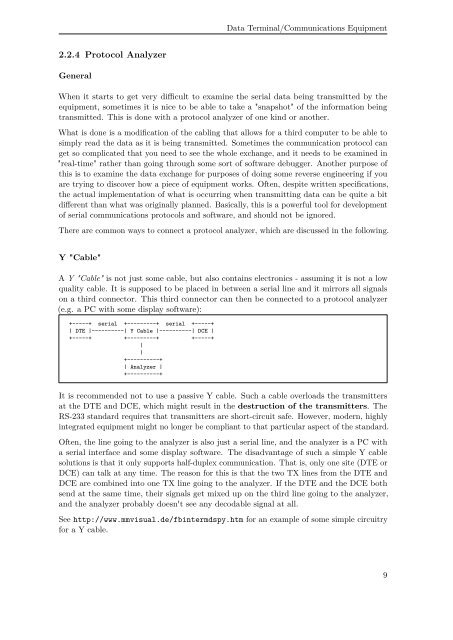
Y "Cable"<br />
A Y "Cable" is not just some cable, but also contains electronics - assuming it is not a low<br />
quality cable. It is supposed to be placed in between a serial line and it mirrors all signals<br />
on a third connector. This third connector can then be connected to a protocol analyzer<br />
(e.g. a PC with some display software):<br />
+-----+ serial +---------+ serial +-----+<br />
| DTE |----------| Y Cable |----------| DCE |<br />
+-----+ +---------+ +-----+<br />
|<br />
|<br />
+----------+<br />
| Analyzer |<br />
+----------+<br />
It is recommended not to use a passive Y cable. Such a cable overloads the transmitters<br />
at the DTE and DCE, which might result in the destruction of the transmitters. The<br />
RS-233 standard requires that transmitters are short-circuit safe. However, modern, highly<br />
integrated equipment might no longer be compliant to that particular aspect of the standard.<br />
Often, the line going to the analyzer is also just a serial line, and the analyzer is a PC with<br />
a serial interface and some display software. The disadvantage of such a simple Y cable<br />
solutions is that it only supports half-duplex communication. That is, only one site (DTE or<br />
DCE) can talk at any time. The reason for this is that the two TX lines from the DTE and<br />
DCE are combined into one TX line going to the analyzer. If the DTE and the DCE both<br />
send at the same time, their signals get mixed up on the third line going to the analyzer,<br />
and the analyzer probably doesn't see any decodable signal at all.<br />
See http://www.mmvisual.de/fbintermdspy.htm for an example of some simple circuitry<br />
for a Y cable.<br />
9