Serial Programming - upload.wikimedia....
Serial Programming - upload.wikimedia....
Serial Programming - upload.wikimedia....

Create successful ePaper yourself
Turn your PDF publications into a flip-book with our unique Google optimized e-Paper software.
8250 UART <strong>Programming</strong><br />
3.4.3 ISR Cleanup<br />
One area that you have to interact on a regular basis when using interrupt controllers is to<br />
inform the 8259 PIC controller that the interrupt service routine is completed. When your<br />
software is performing an interrupt handler, there is no automated method for the CPU<br />
to signal to the 8259 chip that you have finished, so a specific "register" in the PIC needs<br />
to be set to let the next interrupt handler be able to access the computer system. Typical<br />
software to accomplish this is like the following:<br />
Port[$20] := $20;<br />
This is sending the command called "End of Interrupt" or often written as an abbreviation<br />
simply "EOI". There are other commands that can be sent to this register, but for our<br />
purposes this is the only one that we need to concern ourselves with.<br />
Now this will clear the "master" PIC, but if you are using a device that is triggered on the<br />
"slave" PIC, you also need to inform that chip as well that the interrupt service has been<br />
completed. This means you need to send "EOI" to that chip as well in a manner like this:<br />
Port[$A0] := $20;<br />
Port[$20] := $20;<br />
There are other things you can do to make your computer system work smoothly, but let's<br />
keep things simple for now.<br />
3.4.4 PIC Device Masking<br />
Before we leave the subject of the 8259 PIC, I'd like to cover the concept of device masking.<br />
Each one of the devices that are attached to the PIC can be "turned on" or "turned off"<br />
from the viewpoint of how they can interrupt the CPU through the PIC chip. Usually as an<br />
application developer all we really care about is if the device is turned on, although if you<br />
are trying to isolate performance issues you might turn off some other devices. Keep in mind<br />
that if you turn a device "off", the interrupt will not work until it is turned back on. That<br />
can include the keyboard or other critical devices you may need to operate your computer.<br />
The register to set this mask is called "Operation Control Word 1" or "OCW1". This is<br />
located at the PIC base address + 1, or for the "Master" PIC at Port I/O Address $21.<br />
This is where you need to go over bit manipulation, which I won't cover in detail here. The<br />
following tables show the related bits to change in order to enable or disable each of the<br />
hardware interrupt devices:<br />
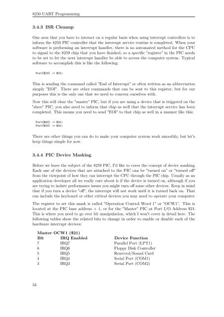
Master OCW1 ($21)<br />
Bit IRQ Enabled Device Function<br />
7 IRQ7 Parallel Port (LPT1)<br />
6 IRQ6 Floppy Disk Controller<br />
5 IRQ5 Reserved/Sound Card<br />
4 IRQ4 <strong>Serial</strong> Port (COM1)<br />
3 IRQ3 <strong>Serial</strong> Port (COM2)<br />
34