Serial Programming - upload.wikimedia....
Serial Programming - upload.wikimedia....
Serial Programming - upload.wikimedia....

You also want an ePaper? Increase the reach of your titles
YUMPU automatically turns print PDFs into web optimized ePapers that Google loves.
8250 UART <strong>Programming</strong><br />
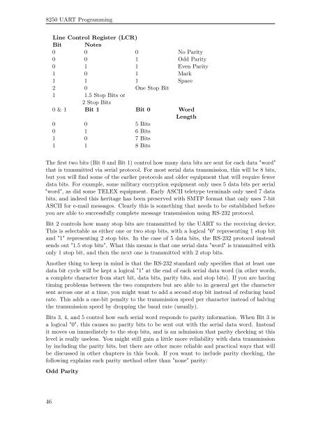
Line Control Register (LCR)<br />
Bit Notes<br />
0 0 0 No Parity<br />
0 0 1 Odd Parity<br />
0 1 1 Even Parity<br />
1 0 1 Mark<br />
1 1 1 Space<br />
2 0 One Stop Bit<br />
1 1.5 Stop Bits or<br />
2 Stop Bits<br />
0 & 1 Bit 1 Bit 0 Word<br />
Length<br />
0 0 5 Bits<br />
0 1 6 Bits<br />
1 0 7 Bits<br />
1 1 8 Bits<br />
The first two bits (Bit 0 and Bit 1) control how many data bits are sent for each data "word"<br />
that is transmitted via serial protocol. For most serial data transmission, this will be 8 bits,<br />
but you will find some of the earlier protocols and older equipment that will require fewer<br />
data bits. For example, some military encryption equipment only uses 5 data bits per serial<br />
"word", as did some TELEX equipment. Early ASCII teletype terminals only used 7 data<br />
bits, and indeed this heritage has been preserved with SMTP format that only uses 7-bit<br />
ASCII for e-mail messages. Clearly this is something that needs to be established before<br />
you are able to successfully complete message transmission using RS-232 protocol.<br />
Bit 2 controls how many stop bits are transmitted by the UART to the receiving device.<br />
This is selectable as either one or two stop bits, with a logical "0" representing 1 stop bit<br />
and "1" representing 2 stop bits. In the case of 5 data bits, the RS-232 protocol instead<br />
sends out "1.5 stop bits". What this means is that one serial data "word" is transmitted with<br />
only 1 stop bit, and then the next one is transmitted with 2 stop bits.<br />
Another thing to keep in mind is that the RS-232 standard only specifies that at least one<br />
data bit cycle will be kept a logical "1" at the end of each serial data word (in other words,<br />
a complete character from start bit, data bits, parity bits, and stop bits). If you are having<br />
timing problems between the two computers but are able to in general get the character<br />
sent across one at a time, you might want to add a second stop bit instead of reducing baud<br />
rate. This adds a one-bit penalty to the transmission speed per character instead of halving<br />
the transmission speed by dropping the baud rate (usually).<br />
Bits 3, 4, and 5 control how each serial word responds to parity information. When Bit 3 is<br />
a logical "0", this causes no parity bits to be sent out with the serial data word. Instead<br />
it moves on immediately to the stop bits, and is an admission that parity checking at this<br />
level is really useless. You might still gain a little more reliability with data transmission<br />
by including the parity bits, but there are other more reliable and practical ways that will<br />
be discussed in other chapters in this book. If you want to include parity checking, the<br />
following explains each parity method other than "none" parity:<br />
Odd Parity<br />
46