Serial Programming - upload.wikimedia....
Serial Programming - upload.wikimedia....
Serial Programming - upload.wikimedia....

Create successful ePaper yourself
Turn your PDF publications into a flip-book with our unique Google optimized e-Paper software.
8250 UART <strong>Programming</strong><br />
motherboard of your computer. It may take some time to hunt down these settings, and<br />
it is important to know what these values are when you are trying to write your software.<br />
Often these values can be found in the BIOS setup screens of your computer, or if you can<br />
pause the messages when your computer turns on, they can be found as a part of the boot<br />
process of your computer.<br />
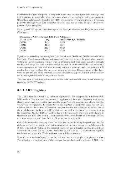
For a "typical" PC system, the following are the Port I/O addresses and IRQs for each serial<br />
COM port:<br />
Common UART IRQ and I/O Port Addresses<br />
COM Port IRQ Base Port I/O address<br />
COM1 IRQ4 $3F8<br />
COM2 IRQ3 $2F8<br />
COM3 IRQ4 $3E8<br />
COM4 IRQ3 $2E8<br />
If you notice something interesting here, you can see that COM3 and COM1 share the same<br />
interrupt. This is not a mistake but something you need to keep in mind when you are<br />
writing an interrupt service routine. The 15 interrupts that were made available through<br />
the 8259 PIC chips still have not been enough to allow all of the devices that are found on a<br />
modern computer to have their own separate hardware interrupt, so in this case you will<br />
need to learn how to share the interrupt with other devices. I'll cover more of that later<br />
when we get into the actual software to access the serial data ports, but for now remember<br />
not to write your software strictly for one device.<br />
The Base Port I/O address is important for the next topic we will cover, which is directly<br />
accessing the UART registers.<br />
3.6 UART Registers<br />
The UART chip has a total of 12 different registers that are mapped into 8 different Port<br />
I/O locations. Yes, you read that correct, 12 registers in 8 locations. Obviously that means<br />
there is more than one register that uses the same Port I/O location, and affects how the<br />
UART can be configured. In reality, two of the registers are really the same one but in a<br />
different context, as the Port I/O address that you transmit the characters to be sent out of<br />
the serial data port is the same address that you can read in the characters that are sent to<br />
the computer. Another I/O port address has a different context when you write data to it<br />
than when you read data from it... and the number will be different after writing the data<br />
to it than when you read data from it. More on that in a little bit.<br />
One of the issues that came up when this chip was originally being designed was that the<br />
designer needed to be able to send information about the baud rate of the serial data with<br />
16 bits. This actually takes up two different "registers" and is toggled by what is called the<br />
"Divisor Latch Access Bit" or "DLAB". When the DLAB is set to "1", the baud rate registers<br />
can be set and when it is "0" the registers have a different context.<br />
Does all this sound confusing? It can be, but lets take it one simple little piece at a time.<br />
The following is a table of each of the registers that can be found in a typical UART chip:<br />
36