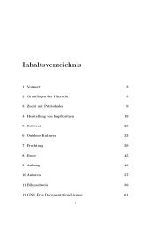
Serial Programming - upload.wikimedia....
Serial Programming - upload.wikimedia....
Serial Programming - upload.wikimedia....

You also want an ePaper? Increase the reach of your titles
YUMPU automatically turns print PDFs into web optimized ePapers that Google loves.
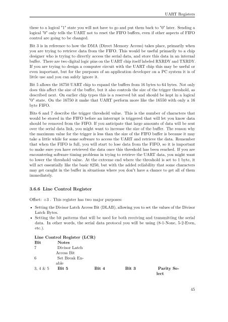
UART Registers<br />
these to a logical "1" state you will not have to go and put them back to "0" later. Sending a<br />
logical "0" only tells the UART not to reset the FIFO buffers, even if other aspects of FIFO<br />
control are going to be changed.<br />
Bit 3 is in reference to how the DMA (Direct Memory Access) takes place, primarily when<br />
you are trying to retrieve data from the FIFO. This would be useful primarily to a chip<br />
designer who is trying to directly access the serial data, and store this data in an internal<br />
buffer. There are two digital logic pins on the UART chip itself labeled RXRDY and TXRDY.<br />
If you are trying to design a computer circuit with the UART chip this may be useful or<br />
even important, but for the purposes of an application developer on a PC system it is of<br />
little use and you can safely ignore it.<br />
Bit 5 allows the 16750 UART chip to expand the buffers from 16 bytes to 64 bytes. Not only<br />
does this affect the size of the buffer, but it also controls the size of the trigger threshold, as<br />
described next. On earlier chip types this is a reserved bit and should be kept in a logical<br />
"0" state. On the 16750 it make that UART perform more like the 16550 with only a 16<br />
byte FIFO.<br />
Bits 6 and 7 describe the trigger threshold value. This is the number of characters that<br />
would be stored in the FIFO before an interrupt is triggered that will let you know data<br />
should be removed from the FIFO. If you anticipate that large amounts of data will be sent<br />
over the serial data link, you might want to increase the size of the buffer. The reason why<br />
the maximum value for the trigger is less than the size of the FIFO buffer is because it may<br />
take a little while for some software to access the UART and retrieve the data. Remember<br />
that when the FIFO is full, you will start to lose data from the FIFO, so it is important<br />
to make sure you have retrieved the data once this threshold has been reached. If you are<br />
encountering software timing problems in trying to retrieve the UART data, you might want<br />
to lower the threshold value. At the extreme end where the threshold is set to 1 byte, it<br />
will act essentially like the basic 8250, but with the added reliability that some characters<br />
may get caught in the buffer in situations where you don't have a chance to get all of them<br />
immediately.<br />
3.6.6 Line Control Register<br />
Offset: +3 . This register has two major purposes:<br />
• Setting the Divisor Latch Access Bit (DLAB), allowing you to set the values of the Divisor<br />
Latch Bytes.<br />
• Setting the bit patterns that will be used for both receiving and transmitting the serial<br />
data. In other words, the serial data protocol you will be using (8-1-None, 5-2-Even,<br />
etc.).<br />
Line Control Register (LCR)<br />
Bit Notes<br />
7 Divisor Latch<br />
Access Bit<br />
6 Set Break Enable<br />
3, 4 & 5 Bit 5 Bit 4 Bit 3 Parity Select<br />
45