Serial Programming - upload.wikimedia....
Serial Programming - upload.wikimedia....
Serial Programming - upload.wikimedia....
Create successful ePaper yourself
Turn your PDF publications into a flip-book with our unique Google optimized e-Paper software.
8250 UART <strong>Programming</strong><br />
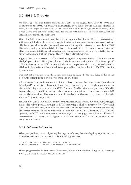
3.2 8086 I/O ports<br />
We should go back even further than the Intel 8086, to the original Intel CPU, the 4004, and<br />
its successor, the 8008. All computer instructions, or op-codes, for the 8008 still function in<br />
today's Intel chips, so even port I/O tutorials written 30 years ago are valid today. The<br />
newer CPUs have enhanced instructions for dealing with more data more efficiently, but the<br />
original instructions are still there.<br />
When the 8008 was released, Intel tried to devise a method for the CPU to communicate<br />
with external devices. They chose a method called I/O port architecture, meaning that the<br />
chip has a special set of pins dedicated to communicating with external devices. In the 8008,<br />
this meant that there were a total of sixteen (16) pins dedicated to communicating with the<br />
chip. The exact details varied based on chip design and other factors too detailed for the<br />
current discussion, but the general theory is fairly straightforward.<br />
Eight of the pins represent an I/O code that signaled a specific device. This is known as<br />
the I/O port. Since this is just a binary code, it represents the potential to hook up 256<br />
different devices to the CPU. It gets a little more complicated than that, but still you can<br />
think of it from software like a small-town post-office that has a bank of 256 PO boxes for<br />
its customers.<br />
The next set of pins represent the actual data being exchanged. You can think of this as the<br />
postcards being put into or removed from the PO boxes.<br />
All the external device has to do is look for its I/O code, and then when it matches what it<br />
is "assigned" to look for, it has control over the corresponding port. An pin signals whether<br />
the data is being sent to or from the CPU. For those familiar with setting up early PCs, this<br />
is also where I/O conflicts happen: when two or more devices try to access the same I/O<br />
port at the same time. This was a source of heartburn on those early systems, particularly<br />
when adding new equipment.<br />
Incidentally, this is very similar to how conventional RAM works, and some CPU designs<br />
mimic this whole process straight in RAM, reserving a block of memory for I/O control.<br />
This has some problems, including the fact that it chews up a portion of potential memory<br />
that could be used for software instead. It ends up that with the IBM PC and later PC<br />
systems, both I/O methods are used extensively, so it really gets complicated. For serial<br />
communication, however, we are going to stick with the port I/O method, as that is how<br />
the 8250 chip works.<br />
3.2.1 Software I/O access<br />
When you get down to actually using this in your software, the assembly language instruction<br />
to send or receive data to port 9 looks something like this:<br />
out 9, ah ; sending data from register ah out to port 9<br />
in ah, 9 ; getting data from port 9 and putting it in register ah<br />
When programming in higher level languages, it gets a bit simpler. A typical C language<br />
Port I/O library is usually written like this:<br />
28


