capriz 25 capriz 28 - Heatline
capriz 25 capriz 28 - Heatline
capriz 25 capriz 28 - Heatline

You also want an ePaper? Increase the reach of your titles
YUMPU automatically turns print PDFs into web optimized ePapers that Google loves.
10.9 On installing the flue, determine the required<br />
length of the outer air duct by measuring the<br />
distance 'L' (Figure 14) from the face of the<br />
external wall to the back of boiler's elbow<br />
connecting collar. The measurement for the inner<br />
flue duct will be 'L' + 20mm<br />
soak away. Note if a soak way is used the drain must<br />
terminate at least 500mm from the external wall.<br />
10.17 Extract the bottom part of condensate trap, by<br />
turning anti-clockwise and fill it with approximately 50<br />
cc water re-connecting it to the boiler.<br />
(Figure 16).<br />
10.10 Measuring from the back of the terminal<br />
connection, mark distance 'L' onto the outer air<br />
duct. (figure 14 )<br />
L+20 mm<br />
‘<br />
L<br />
‘<br />
Figure 16<br />
16<br />
Waste<br />
Figure 15<br />
Figure 14<br />
‘<br />
L<br />
‘<br />
External<br />
wall face<br />
10.11 Cuttheouter air duct only to the required length<br />
ensuring that the cut is square and free from burrs.<br />
10.12 Measuring from the back of the terminal<br />
connection, mark distance 'L' + 20mm (figure 14 ) onto<br />
the inner flue duct and cut the duct to size, ensuring<br />
that the cut is square and free from burrs.<br />
10.13 Pass the flue assembly through the wall and<br />
connect the assembly to the boiler, ensuring that both<br />
the air and flue duct joints are fully pushed home into<br />
the connecting elbow's collar.<br />
10.14 With the flue and joints secured fit the flue trim<br />
to the external wall surface using suitable mastic.<br />
Note. Where internal access only is available, the flue<br />
trim must be attached to the flue assembly prior to<br />
passing the assembly through the wall.<br />
10.15 For maximum flue lengths refer to the Technical<br />
Data, section 2 in this manual<br />
10.16 Condensing type boilers must be connected to<br />
the drainage system. A plastic drain must be fitted to<br />
allow discharge of condensate to a drain.<br />
Condensate should, if possible, be discharged into the<br />
internal household draining system. If this is not<br />
practical, discharge can be made externally into the<br />
household drainage system or a purpose designed<br />
CONDENSATE<br />
OUTLET PIPE<br />
10.18 Connect the condensate drainage pipe to the<br />
drainage system.(Figure 16) Note due to the acidic nature<br />
of the condensate the drainage system must be made of<br />
non-corrosive material such as plastic tubing. More<br />
detailed information on condensate discharge is provided<br />
in BS 6798 (Specification for installation of gas fired hot<br />
water boilers of rated input not exceeding 70kW)<br />
10.19 Connect the domestic hot water, cold water inlet,<br />
heating system flow & return and pressure relief valve<br />
pipework to the boiler fittings, ensuring that the<br />
pipework has been correctly flushed before final<br />
connection. The electrical connections to the boiler must<br />
be in accordance to Section 9 of these instructions.<br />
NOTE: Place the filling loop in a visible accessible<br />
position and instruct the user how to pressurise the<br />
system if there is a fall in pressure.<br />
11. Gas Supply<br />
CONDENSATE<br />
TRAP<br />
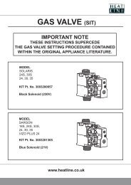
11.1 The gas supply pipe must be capable of supplying<br />
the quantity of gas required by the boiler (see Technical<br />
Data, section 2) in addition to the demand of any other<br />
gas appliances being serviced from that supply.<br />
11.2 The internal diameter of the gas supply from the<br />
meter to the boiler's gas inlet connection must not be<br />
less than 22mm.<br />
11.3 The meter governor must be capable of delivering a<br />
nominal pressure of 20mbar (for natural gas).<br />
11.4 On final connection of the gas supply to the boiler,<br />
the complete gas installation including the gas meter,<br />
must be tested for tightness and purged.<br />
Page 16