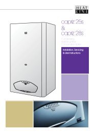
capriz 25 capriz 28 - Heatline
capriz 25 capriz 28 - Heatline
capriz 25 capriz 28 - Heatline
Create successful ePaper yourself
Turn your PDF publications into a flip-book with our unique Google optimized e-Paper software.
3<br />
4<br />
5<br />
17<br />
36<br />
GENERAL DESCRIPTION OF BOILER<br />
The CAPRIZ <strong>25</strong> / CAPRIZ <strong>28</strong> is a combined domestic hot<br />
water and central heating appliance. The internal<br />
control unit electronically provides direct burner ignition<br />
and combustion supervision along with continuous<br />
modulation of the burner’s gas supply.<br />
By means of a manual switch the boiler can be set to<br />
operate in one of two operating modes, domestic hot<br />
water only or domestic hot water and central heating.<br />
DOMESTIC HOT WATER MODE:<br />
When hot water demand is requested the boiler will<br />
fire automatically. An integral pump is then energised<br />
and hot water from the boilers primary circuit is<br />
circulated through the secondary heat exchanger,<br />
allowing the instantaneous transferral of heat to the<br />
incoming cold water. The secondary heat exchanger is<br />
protected against an internal build up of lime scale by<br />
limiting the hot water temperature at the tap to a<br />
maximum of 64°C. Hot water will continue to flow<br />
through the tap until no longer required. When the<br />
demand for hot water ceases the integral pump may<br />
continue to run for a short while to dissipate any<br />
excess heat within the boiler.<br />
DOMESTIC HOT WATER AND CENTRAL HEATING<br />
MODE:<br />
When heating demand is requested the boiler will fire<br />
automatically. An integral pump is then energised and<br />
hot water from the boilers primary circuit is circulated<br />
around the heating systems pipe-work and radiators.<br />
The heat output from the boiler is automatically<br />
adjusted by the boiler’s internal control unit to match<br />
the heating demand. As the water temperature of the<br />
heating system increases the gas input to the burner<br />
decreases, conserving energy and increasing<br />
efficiency. When the demand for heating no longer<br />
exists, either the room thermostat is satisfied or the<br />
heating period has ended, the burner will shut down<br />
and the boiler will revert to stand-by, waiting to<br />
respond to the next heating demand. The integral<br />
pump may continue to run after shut down for a short<br />
while to dissipate any excess heat within the boiler.<br />
ACCESS TO THE BOILER CONTROLS<br />
The boiler controls are sited at the bottom of the boiler’s<br />
front case. (figure 1)<br />
1<br />
6<br />
2<br />
1<br />
7<br />
8<br />
24<br />
1- Timer<br />
2- D.H.W. temperature control<br />
3- Function switch<br />
Please Note. When domestic hot water is called for<br />
during the heating mode, the boiler will automatically<br />
revert to domestic hot water mode until the demand for<br />
hot water ceases.<br />
NOTE: Depending on the boiler set up there may be a<br />
delay of 45secs before the boiler re-fires.<br />
BOILER CONTROLS<br />
23<br />
9<br />
10<br />
22<br />
11<br />
0<br />
21<br />
1<br />
12<br />
20<br />
13<br />
19<br />
18<br />
14<br />
15<br />
16<br />
2<br />
The function and operation of the main controls located<br />
on the control panel fascia (figure 2) is as follows:<br />
1. Function switch. This is the boilers main operating<br />
switch. In the position the boiler is in stand-by<br />
mode and power supply is ON. For the boiler to<br />
operate the switch must be in the<br />
position.<br />
6<br />
bar<br />
3 4<br />
Figure 2<br />
4- C.Heating temperature control<br />
5- System pressure gauge<br />
6- LED display<br />
When switched to the position the boiler will<br />
operate only to supply domestic hot water.<br />
(Summer use) For the boiler to operate to give<br />
both central heating and domestic hot water the<br />
1<br />
0<br />
2<br />
bar<br />
4<br />
3<br />
or<br />
5<br />
switch must be in the<br />
position (Winter use)<br />
Figure 1<br />
2. Central Heating temperature control. The position<br />
of this control dial will determine the temperature<br />
of the water delivered to the radiators. The water<br />
temperature can be set from a minimum of 30º C<br />
(anticlockwise stop position) to a maximum of 85º C<br />
(clockwise stop position.)<br />
Page 36


