capriz 25 capriz 28 - Heatline
capriz 25 capriz 28 - Heatline
capriz 25 capriz 28 - Heatline

You also want an ePaper? Increase the reach of your titles
YUMPU automatically turns print PDFs into web optimized ePapers that Google loves.
24<br />
Open one or more hot water taps to drain the<br />
domestic hot water circuit.<br />
Disconnect the cold water inlet connection to the<br />
boiler.<br />
Clean and inspect the filter, replace if necessary<br />
as described in (18.20).<br />
Re-fit the filter and reinstate the cold water inlet<br />
connection to the boiler, fit new gasket as<br />
required.<br />
Fully open the isolating valve on boiler's cold<br />
water inlet and check for leaks.<br />
18.12 On completing the service reassemble the boiler<br />
components in reverse order of removal, ensuring that<br />
all component joints and gaskets are sound. Any<br />
damaged seal or gasket must be replaced.<br />
18.13 Reinstate the boiler's electrical and gas supplies<br />
and check for gas soundness and correct boiler<br />
operation.<br />
CAUTION!<br />
While there are no substances harmful to health<br />
contained within this appliance, some component parts<br />
of the boiler (insulation pads, gaskets and rope seals)<br />
are manufactured from man made fibres. When<br />
damaged or broken these fibres may cause a<br />
temporary irritation. High dust levels may irritate eyes<br />
and upper respiratory system. It is important therefore,<br />
that sensible precautions are applied when exchanging<br />
components.<br />
19. Component Replacement<br />
19.1 Ensure that both the electrical and gas supplies<br />
to the boiler are isolated before replacing any<br />
component part.<br />
19.2 To prevent the need to drain the entire heating<br />
system when replacing the boiler's integral pump,<br />
expansion vessel, safety relief valve and pressure<br />
sensor, the boiler’s hydraulic circuit may be isolated<br />
from the central heating circuit by closing the boilers<br />
isolation valves. Opening the discharge valve will then<br />
drain the boiler’s hydraulic circuit. Note clean the<br />
valve seat to ensure it seals before re-filling the<br />
boiler.<br />
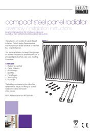
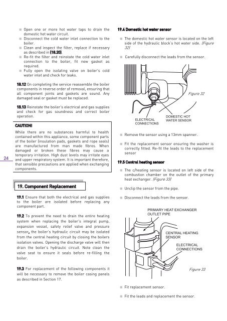
19.4 Domestic hot water sensor<br />
The domestic hot water sensor is located on the left<br />
side of the hydraulic block’s hot water side. (Figure<br />
32)<br />
Carefully disconnect the leads from the sensor.<br />
ELECTRICAL<br />
CONNECTIONS<br />
Remove the sensor using a 13mm spanner.<br />
Fit the replacement sensor ensuring the washer is<br />
correctly fitted. Re-fit the leads to the replacement<br />
sensor<br />
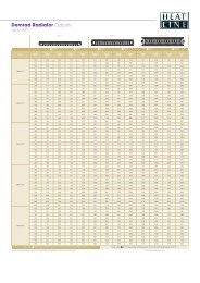
19.5 Central heating sensor<br />
DOMESTIC HOT<br />
WATER SENSOR<br />
The c/heating sensor is located on left side of the<br />
combustion chamber on the outlet of the primary<br />
heat exchanger. (Figure 33)<br />
Unclip the sensor from the pipe.<br />
Disconnect the leads from the sensor.<br />
Figure 32<br />
PRIMARY HEAT EXCHANGER<br />
OUTLET PIPE<br />
CENTRAL HEATING<br />
SENSOR<br />
ELECTRICAL<br />
CONNECTIONS<br />
19.3 For replacement of the following components it<br />
will be necessary to remove the boiler casing panels<br />
as described in Section 17.<br />
Fit replacement sensor.<br />
Fit the leads and replacement the sensor.<br />
Figure 33<br />
Page 24