Frequency converter FKO - Brinkmann Pumps
Frequency converter FKO - Brinkmann Pumps
Frequency converter FKO - Brinkmann Pumps

Create successful ePaper yourself
Turn your PDF publications into a flip-book with our unique Google optimized e-Paper software.
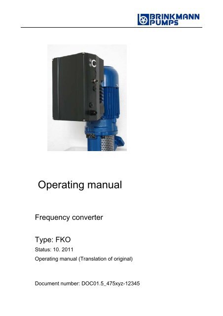
Operating manual<br />
<strong>Frequency</strong> <strong>converter</strong><br />
Type: <strong>FKO</strong><br />
Status: 10. 2011<br />
Operating manual (Translation of original)<br />
Document number: DOC01.5_475xyz-12345
LEGAL NOTICE<br />
BRINKMANN PUMPEN<br />
K. H. <strong>Brinkmann</strong> GmbH & Co. KG<br />
Friedrichstraße 2<br />
58791 Werdohl<br />
Germany<br />
Tel. +49 (0)2392 5006-0<br />
Fax +49 (0)2392 5006-180<br />
Sales@<strong>Brinkmann</strong><strong>Pumps</strong>.de<br />
Exclusion of liability<br />
All names of usage, trade names, product names or other designations<br />
given in this manual may also be legally protected even without special<br />
labelling (e.g. as a trademark). The BRINKMANN company assumes no<br />
liability for their free usage.<br />
The illustrations and texts have been compiled with great care.<br />
Nevertheless, the possibility of errors cannot be ruled out. The compilation<br />
is made without any guarantee.<br />
General note on equal treatment<br />
The BRINKMANN company publishers are aware of the meaning of<br />
language with regard to the equality of women and men and always make<br />
an effort to reflect this in the documentation. The continuous rendition of<br />
gender-equitable formulations, however, conflicted with the easy readability<br />
of the text. For this reason, the masculine form has been used as a rule.<br />
© 2011 BRINKMANN GmbH & Co. KG<br />
All rights reserved by BRINKMANN, including those of reproduction by<br />
photocopy and storage in electronic media. Commercial use or distribution<br />
of the texts, displayed models, diagrams and photographs appearing in this<br />
product is not permitted. The manual may not be reproduced, stored,<br />
transmitted or translated in any form or by means of any medium - in whole<br />
or in part - without prior written permission.<br />
2 Operating manual <strong>FKO</strong>
Table of contents<br />
1 Important information ................................................................. 6<br />
1.1 Notes on the documentation ...................................................... 6<br />
1.1.1 Other applicable documents .............................................. 6<br />
1.1.2 Storing the documentation ................................................ 6<br />
1.1.3 Symbols ..................................................................... 6<br />
1.2 Qualified staff ........................................................................ 7<br />
1.3 CE marking .......................................................................... 7<br />
1.4 Safety instructions .................................................................. 7<br />
1.4.1 General information ........................................................ 8<br />
1.4.2 Transport & storage ........................................................ 9<br />
1.4.3 Commissioning ............................................................ 10<br />
1.4.4 Operation ................................................................... 11<br />
1.4.5 Repairs ..................................................................... 12<br />
1.4.6 Disassembly & disposal .................................................. 12<br />
1.5 Proper use .......................................................................... 13<br />
1.6 Responsibility ...................................................................... 13<br />
1.7 Contacts for information .......................................................... 14<br />
2 verview of the drive control ......................................................... 15<br />
2.1 Description of the <strong>FKO</strong> drive control ............................................ 15<br />
3 Installation .............................................................................. 15<br />
3.1 Safety instructions during installation ........................................... 15<br />
3.2 Installation requirements .......................................................... 16<br />
3.2.1 Suitable ambient conditions ............................................. 16<br />
3.2.2 Suitable installation location for the motor integrated drive control 17<br />
3.2.3 Basic connection versions ............................................... 17<br />
3.2.4 Short circuit and ground protection ..................................... 18<br />
3.2.5 Wiring instructions ........................................................ 19<br />
3.2.6 Preventing electromagnetic interferences ............................. 19<br />
3.3 Installing the drive control integrated in the motor ............................ 20<br />
3.3.1 Power connection ......................................................... 20<br />
3.3.2 Connections for brake resistor .......................................... 21<br />
3.3.3 Control connections ....................................................... 21<br />
3.3.4 Terminal connection diagram ............................................ 24<br />
3.4 Installing the wall-mounted drive control ....................................... 24<br />
3.4.1 Suitable installation location for wall mounting ........................ 24<br />
3.4.2 Mechanical installation ................................................... 26<br />
3.4.3 Power connection ......................................................... 30<br />
3.4.4 Brake chopper ............................................................. 30<br />
3.4.5 Control connections ....................................................... 30<br />
4 Commissioning ........................................................................ 31<br />
4.1 Safety instructions during commissioning ...................................... 31<br />
4.2 Communication .................................................................... 32<br />
4.3 Block diagram ...................................................................... 33<br />
4.4 Start-up steps ...................................................................... 34<br />
5 Parameters .............................................................................. 35<br />
5.1 Safety instructions for dealing with parameters ............................... 35<br />
5.2 General information on parameters ............................................. 35<br />
Operating manual <strong>FKO</strong> 3
5.2.1 Explanation of operating modes ........................................ 35<br />
5.2.2 Structure of the parameter tables ....................................... 39<br />
5.3 Application parameters ........................................................... 40<br />
5.3.1 Basic parameters.......................................................... 40<br />
5.3.2 Preset speed mode ....................................................... 46<br />
5.3.3 Motorized potentiometer ................................................. 47<br />
5.3.4 PID process controller .................................................... 48<br />
5.3.5 Analogue inputs ........................................................... 51<br />
5.3.6 Digital inputs ............................................................... 53<br />
5.3.7 Analogue output ........................................................... 54<br />
5.3.8 Digital outputs ............................................................. 55<br />
5.3.9 Relay ........................................................................ 56<br />
5.3.10 External fault ............................................................... 58<br />
5.3.11 Motor current limit ......................................................... 58<br />
5.3.12 Stall detection .............................................................. 59<br />
5.4 Performance parameters ......................................................... 60<br />
5.4.1 Motor data .................................................................. 60<br />
5.4.2 I 2 T ........................................................................... 63<br />
5.4.3 Switching frequency ...................................................... 64<br />
5.4.4 Controller data ............................................................. 64<br />
5.4.5 Squared characteristic .................................................... 67<br />
6 Error detection and troubleshooting .............................................. 68<br />
6.1 List of the LED flash codes for error recognition .............................. 69<br />
6.2 List of errors and system errors .................................................. 70<br />
7 Technical data .......................................................................... 73<br />
7.1 General data ........................................................................ 73<br />
8 Optional accessories ................................................................. 75<br />
9 Guidelines, Norms and Standards ................................................. 75<br />
9.1 EMV limit classes .................................................................. 75<br />
9.2 Classification acc. to IEC/EN 61800-3 .......................................... 76<br />
9.3 Standards and guidelines ......................................................... 76<br />
9.4 Required markings for UL ........................................................ 77<br />
9.5 Quickstart guide .................................................................... 78<br />
4 Operating manual <strong>FKO</strong>
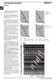
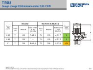
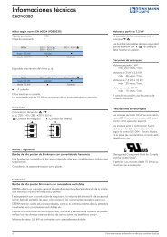
Overview of installation sizes<br />
Dimensioned drawings<br />
L<br />
The drive controls are available in the following performance classes and<br />
under the specified installation size names.<br />
Installation size<br />
<strong>FKO</strong><br />
motor integrated<br />
Recommended<br />
motor power [kW]<br />
Dimensions<br />
[L x B x H] mm<br />
Installation sizes<br />
Operating manual <strong>FKO</strong> 5<br />
H<br />
A B C D<br />
0.55 / 0.75 / 1.1<br />
/ 1.5<br />
2.2 / 3.0 / 4.0 5.5 / 7.5<br />
B<br />
11.0 / 15.0 / 18.5<br />
/ 22.0<br />
233 x 153 x 120 270 x 189 x 133 307 x 223 x 181 414 x 294 x 238
Important information<br />
1 Important information<br />
This chapter contains important information on the safe handling of the<br />
product and on the operating manual.<br />
1.1 Notes on the documentation<br />
The following notes are a directory for the overall documentation.<br />
We assume no liability for any damage resulting from the non-observance<br />
of this manual.<br />
Provide this manual to the operator of the system so that it will be available<br />
when required.<br />
1.1.1 Other applicable documents<br />
This refers to all manuals that describe how to operate the drive control<br />
system, and any other manuals for equipment parts in use.<br />
1.1.2 Storing the documentation<br />
Store this manual and all other applicable documents safely so they will be<br />
available when required.<br />
1.1.3 Symbols<br />
DANGER<br />
Note on safety: Non-observance will result in death or serious injury.<br />
WARNING<br />
Note on safety: Non-observance can lead to death or serious injury.<br />
ATTENTION!<br />
Non-observance can result in material being damaged and can affect the<br />
function of the drive control.<br />
6 Operating manual <strong>FKO</strong>
Important information<br />
Supplemental information on operating the drive<br />
control.<br />
� Action: This symbol indicates that you have to perform an action. The<br />
required actions are described step by step.<br />
� This symbol indicates the result of an action.<br />
1.2 Qualified staff<br />
In the context of this operating manual and the notes relating to the product<br />
itself, qualified staff refers to electronic specialists that are familiar with the<br />
installation, assembly, start-up and operation of the drive control and with<br />
the dangers involved, and whose specialist training and knowledge of<br />
relevant standards and regulations provide them with the necessary<br />
abilities.<br />
1.3 CE marking<br />
With the CE marking, we as the manufacturer of the device confirm that the<br />
drive control meets the basic requirements of the following guidelines:<br />
– Directive on Electromagnetic Compatibility (Directive 2004/108/EC of the<br />
Council)<br />
– Low Voltage Directive (Directive 2006/95/EC of the Council)<br />
You will find the declaration of conformity at the end of this manual.<br />
1.4 Safety instructions<br />
The following warnings, precautionary measures and comments are<br />
provided for your safety and serve to prevent damage to the drive control<br />
and the components connected to it. This chapter contains warnings and<br />
notes that are generally applicable when handling drive controls. They are<br />
separated into general information, transport & storage, start-up, operation,<br />
repair and dismantling & disposal.<br />
Specific warnings and comments that apply to specific activities are placed<br />
at the start of the appropriate chapters and are repeated and enhanced at<br />
different critical points within these chapters.<br />
Please read this information carefully, as it is provided for your personal<br />
safety and will also support a longer life for the drive control and the<br />
connected devices.<br />
Operating manual <strong>FKO</strong> 7
Important information<br />
1.4.1 General information<br />
WARNING<br />
This drive control contains dangerous voltage and controls revolving<br />
mechanical parts that may be dangerous.<br />
Disregarding warnings or non-compliance with the notes in this manual can<br />
result in death, serious injury or serious damage to property.<br />
� Only appropriately trained persons may perform work on this drive<br />
control. These persons must be familiar with all safety instructions and<br />
all measures relating to installation, operation and maintenance that are<br />
contained in this manual. Proper and safe operation of the drive control<br />
requires proper transport, installation, operation and maintenance.<br />
WARNING<br />
Danger of fire or electric shock.<br />
Improper use, changes and the use of spare parts and accessories not sold<br />
or recommended by the manufacturer of the drive control can cause fire,<br />
electric shock and injury.<br />
� The cooling elements in the drive control and motor can reach<br />
temperatures above 70 °C. Ensure that there is sufficient distance from<br />
neighbouring components during installation. Allow sufficient cooling<br />
time before working on the drive control or the motor. If necessary,<br />
protection should be installed against accidental contact.<br />
ATTENTION!<br />
The drive control can only be operated safely if the required environmental<br />
conditions listed in the “Suitable environmental conditions” chapter are<br />
fulfilled.<br />
ATTENTION!<br />
This operating manual must be accessible near the device and available to<br />
all users.<br />
8 Operating manual <strong>FKO</strong>
Important information<br />
ATTENTION!<br />
Please read these safety instructions and warnings before installation and<br />
start-up; this also applies to all warning signs attached to the device. Make<br />
sure that the warning signs are legible and replace missing or damaged<br />
signs.<br />
1.4.2 Transport & storage<br />
ATTENTION!<br />
Risk of damaging the drive control.<br />
If the notes are not observed, the drive control could be damaged and<br />
destroyed during subsequent start-up.<br />
� Proper and safe operation of the drive control requires proper storage,<br />
set-up and assembly as well as careful operation and maintenance.<br />
The drive control must be protected from mechanical jolts and vibrations<br />
during transport and storage. Protection from impermissible<br />
temperatures (see technical data) must also be guaranteed.<br />
Operating manual <strong>FKO</strong> 9
Important information<br />
1.4.3 Commissioning<br />
WARNING<br />
Danger of injury through electric shock.<br />
Non-observance of warnings can result in serious injury or damage.<br />
� Only hard-wired network connections are permitted. The device must be<br />
grounded (DIN EN 61140; VDE 0140-1).<br />
� <strong>Frequency</strong> <strong>converter</strong>s of the <strong>FKO</strong> series can contain contact currents<br />
(leakage currents) > 3.5 mA. According to chapter 4.3.5.5.2 of DIN EN<br />
61800-5-1, a reinforced protective ground wire (at least 10 mm 2 Cu or<br />
16 mm 2 Al) must be used.<br />
� If three-phase frequency <strong>converter</strong>s are in use, it is not permitted to use<br />
standard type A FI protection switches, or RCDs (residual currentoperated<br />
protective devices) to protect from direct or indirect contact.<br />
According to DIN VDE 0160, section 5.5.2 and EN 50178, section<br />
5.2.11.1, the FI protection switch must be universal current sensitive<br />
(RCD type B).<br />
� The following terminals can lead to dangerous currents even when the<br />
motor is not running:<br />
– Supply terminals X1: L1, L2, L3<br />
– Motor connection terminals X2: U, V, W<br />
– Connecting terminals X6, X7: Relay contacts for relays 1 and 2<br />
� If different voltages are in use (e.g. +24 V/230 V), crossing cable runs<br />
are never permitted. The operator must also ensure compliance with the<br />
applicable regulations (e.g. double or strengthened insulation acc. to DIN<br />
EN 61800-5-1).<br />
� The drive control contains components susceptible to electrical<br />
discharge. These components can be destroyed through improper<br />
handling; therefore, precautionary measures against electrostatic<br />
charges must be taken when work is performed on these components.<br />
10 Operating manual <strong>FKO</strong>
1.4.4 Operation<br />
WARNING<br />
Important information<br />
Danger of injury due to electric shocks or restarting motors.<br />
Non-observance of warnings can result in serious injury or damage.<br />
� Observe the following instructions during operation:<br />
– The drive control works with high voltages.<br />
– When electrical devices are operated, some parts of them are always<br />
subject to dangerous voltage.<br />
– Emergency off equipment according to DIN EN 60204-1; VDE 0113-<br />
1:2007-06 has to be functional in all operating modes of the control<br />
device. Resetting the emergency stop equipment may not result in<br />
uncontrolled or undefined restarting.<br />
– In order to ensure safe disconnection from the mains, the mains cable<br />
has to be all-pole disconnected from the drive control.<br />
– Certain parameter settings can result in the drive control restarting<br />
automatically after the supply voltage has failed.<br />
ATTENTION!<br />
Risk of damaging the drive control.<br />
If the notes are not observed, the drive control could be damaged and<br />
destroyed during subsequent start-up.<br />
� Observe the following instructions during operation:<br />
– The motor parameters, especially the l 2 T settings, have to be<br />
configured properly to provide proper motor overload protection.<br />
– The drive control contains internal motor overload protection. See<br />
P0610 (level 3) and P0335. I 2 T is ON by default. Motor overload<br />
protection can also be ensured via an external PTC.<br />
– The drive control may not be used as “Emergency-off equipment” (see<br />
DIN EN 60204-1; VDE 0113-1:2007-06).<br />
– Drive controls are maintenance-free if operated properly. If the air<br />
contains dust, the cooling fins of the motor and drive control have to<br />
be cleaned regularly.<br />
Operating manual <strong>FKO</strong> 11
Important information<br />
1.4.5 Repairs<br />
ATTENTION!<br />
Risk of damaging the drive control.<br />
If the notes are not observed, the drive control could be damaged and<br />
destroyed during subsequent start-up.<br />
� Repairs of the drive control may only be performed by the BRINKMANN<br />
Service department.<br />
WARNING<br />
Danger of injury through electric shock.<br />
Non-observance of warnings can result in serious injury or damage.<br />
� When the drive control is disconnected from the mains voltage, parts and<br />
connections of the device subject to current may not be touched<br />
immediately in case the condensers are still charged.<br />
1.4.6 Disassembly & disposal<br />
Screw and snap-on connections are easy to release<br />
and allow the drive control to be dismantled into its<br />
individual parts. These parts can be sorted for<br />
recycling. Please comply with local regulations during<br />
disposal.<br />
Components with electronic parts may not be placed in<br />
normal household waste. They have to be collected<br />
separately with old electric and electronic equipment in<br />
accordance with applicable legislation.<br />
12 Operating manual <strong>FKO</strong>
1.5 Proper use<br />
Important information<br />
If the device is installed in a machine, <strong>converter</strong>s may not be started up (i.e.<br />
intended operation may not begin) until it has been determined that the<br />
machine complies with the regulations in EC Directive 2006/42/EC<br />
(machine directive); DIN EN 60204-1; VDE 0113-1:2007-06 must be<br />
observed.<br />
Start-up (i.e. beginning intended operation) is only permitted if the EMV<br />
Directive (2004/108/EC) is complied with.<br />
The harmonised standards of series DIN EN 50178; VDE 0160:1998-04<br />
have to be applied for this drive control along with DIN EN 60439-1; VDE<br />
0660-500:2005-01.<br />
This drive control may not be operated in areas where there is a danger of<br />
explosion.<br />
Repairs may only be performed by authorised repair bodies. Independent<br />
and unauthorised intervention can result in death, injury and damage. The<br />
warranty provided by BRINKMANN will be invalidated in this case.<br />
External mechanical loads such as stepping on the housing are not<br />
permitted.<br />
1.6 Responsibility<br />
Using drive units in equipment that is not fixed is<br />
considered as an exceptional environmental condition<br />
and is only permitted if allowed by the standards and<br />
guidelines applicable on site.<br />
As a basic principle, electronic devices are not fail-proof. The operator<br />
and/or the contractor setting up the machine or system is responsible for<br />
ensuring that the drive is moved to a safe state if the device fails.<br />
Section “Electrical equipment of machines” in DIN EN 60204-1; VDE 0113-<br />
1:2007-06, “Safety of machinery” describes the safety requirements for<br />
electric control units. These are provided for the safety of persons and<br />
machines, and in order to retain the functional capability of the machine or<br />
system; they have to be observed.<br />
The function of an emergency-off feature does not have to result in the<br />
power supply for the drive being switched off. In order to prevent danger, it<br />
can be useful to keep individual drives in operation or initiate specific safety<br />
procedures. The performance of emergency-off measures is evaluated by<br />
Operating manual <strong>FKO</strong> 13
Important information<br />
means of a risk assessment for the machine or system and its electrical<br />
equipment, and is determined with a selection of the circuit category<br />
according to DIN EN 13849 “Safety of machinery – Safety-related parts of<br />
control systems”.<br />
1.7 Contacts for information<br />
Further information is available from:<br />
Tel: +49 2392 5006-0<br />
Monday to Friday: 7.00 to 17.00 (local time)<br />
Fax: +49 2392 5006-180<br />
Email: Sales@<strong>Brinkmann</strong><strong>Pumps</strong>.de<br />
Internet address<br />
Customers can access technical and general information from the following<br />
address:<br />
http://www.<strong>Brinkmann</strong><strong>Pumps</strong>.com<br />
14 Operating manual <strong>FKO</strong>
2 Overview of the drive control<br />
Overview of the drive control<br />
This chapter contains information on the scope of delivery for the drive<br />
control and the function description.<br />
2.1 Description of the <strong>FKO</strong> drive control<br />
The <strong>FKO</strong> drive control is a device for speed control in three-phase a.c.<br />
motors.<br />
The drive control can be integrated in the motor (with the standard adapter<br />
plate) or close to the motor (with the wall installation adapter plate).<br />
The permitted ambient temperatures specified under Technical data refer<br />
to operation at nominal load. In many cases of application, higher<br />
temperatures may be permitted after a detailed technical analysis. These<br />
have to be approved by BRINKMANN for each individual case.<br />
3 Installation<br />
3.1 Safety instructions during installation<br />
WARNING<br />
� Installation may be performed only be appropriately qualified employees<br />
who are trained in the set-up, installation, start-up and operation of the<br />
product. Work performed on the drive control by unqualified staff and<br />
non-observance of warnings can result in serious injury or damage.<br />
� The device must be grounded in accordance with DIN EN 61140; VDE<br />
0140, NEC and other relevant standards. Mains connections must be<br />
hardwired.<br />
Operating manual <strong>FKO</strong> 15
Installation<br />
3.2 Installation requirements<br />
3.2.1 Suitable ambient conditions<br />
Altitude of the installation<br />
site:<br />
up to 1,000 m above sea level / over 1,000 m with reduced<br />
performance (1% per 100 m) (max. 2,000 m)<br />
Ambient temperature: -25 °C to +50 °C (different ambient temperatures may be<br />
possible in individual cases)<br />
Relative humidity: ≤ 96%, condensation not permitted<br />
Resistance to vibration and<br />
shock:<br />
Electromagnetic<br />
compatibility:<br />
acc. to FN 942 017 part 4; 5.3.3.3 Combined test 2;<br />
5...200 Hz for sinusoidal oscillation<br />
Immune to interference acc. to DIN EN 61800-3<br />
Cooling: Surface cooling:<br />
installation sizes A to C: free convection;<br />
installation size C: optionally with integrated fan<br />
installation size D: with integrated fans<br />
Tab. 1: Ambient conditions<br />
� Make certain that the housing type (protection type) is suitable for the<br />
operating environment:<br />
– Ensure that the seal between the motor and the adapter plate is<br />
inserted correctly.<br />
– All unused cable screw connections have to be sealed.<br />
– Check that the cover of the drive control is closed and bolted down<br />
tightly.<br />
Although the drive control can, in principle, be subsequently painted, the<br />
user must nevertheless check the material compatibility of the paint that is<br />
to be used. A failure to comply with this can eventually result in the loss of<br />
the protection class (particularly in respect of seals and fibre-optic<br />
elements). The standard colour is black (RAL 9005).<br />
Disassembling the circuit boards (even for the purpose of painting the<br />
housing sections) renders the warranty void!<br />
Mounting points and sealing surfaces must be kept free of paint for<br />
purposes of EMC and earthing!<br />
16 Operating manual <strong>FKO</strong>
Installation<br />
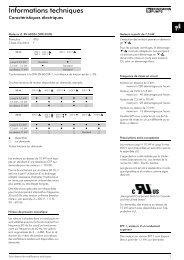
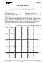
3.2.2 Suitable installation location for the motor integrated drive control<br />
� Ensure that the motor with a motor integrated drive control is only<br />
installed and operated if aligned as shown in the following image.<br />
Fig. 1: Motor installation location/permitted alignments<br />
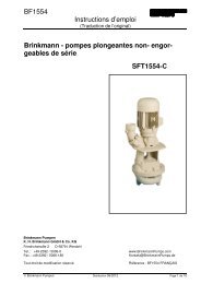
3.2.3 Basic connection versions<br />
Fig. 2: Star or triangle connection for drive controls integrated in the motor<br />
Operating manual <strong>FKO</strong> 17
Installation<br />
ATTENTION!<br />
Risk of damaging the drive control.<br />
The correct phase sequence must be observed when the drive control is<br />
connected, as the motor could otherwise be overloaded.<br />
� Ensure that the phase sequence is correct when connecting the motor.<br />
The supplied assembly material can be used to connect core end sleeves<br />
and cable shoes. Fig. 4 shows the different connection options.<br />
Unused open cable ends in the motor terminal box<br />
must be insulated.<br />
If a PTC or Klixxon is used, the electric jumper fitted on<br />
the connection terminal for the PTC in the delivery<br />
state has to be removed.<br />
The cross-section of the supply line has to be designed according to the<br />
transfer category and the maximum permitted current. The contractor<br />
starting up the device must ensure the power line protection.<br />
3.2.4 Short circuit and ground protection<br />
The drive control contains an internal short circuit and ground protection.<br />
18 Operating manual <strong>FKO</strong>
3.2.5 Wiring instructions<br />
Installation<br />
The control connections of the application card are located inside the drive<br />
control.<br />
The configuration can vary, depending on the version.<br />
Terminals: Plug terminal clamp with activation button<br />
(slot screwdriver, max. width 2.5 mm)<br />
Connection cross-section: 0.5 to 1.5 mm 2 , single-wire, AWG 20 to<br />
AWG 14<br />
Connection cross-section: 0.75 to 1.5 mm 2 , fine-wired, AWG 18 to<br />
AWG 14<br />
Connection cross-section: 0.5 to 1.0 mm 2 , fine-wired, (core end<br />
sleeves with and without plastic collar)<br />
Length of stripped insulation: 9 to 10 mm<br />
3.2.6 Preventing electromagnetic interferences<br />
Screened lines should be used for control circuits where possible. The<br />
screening should be applied to the line end with special care without laying<br />
the leads across longer stretches without screening.<br />
Screening for analogue target values should only be applied on one side of<br />
the drive control.<br />
In principle, control lines should always be laid as far away from powerconducting<br />
lines; it may be necessary to use separate ducts. If lines do<br />
cross, they should do so at an angle of 90°.<br />
Upstream circuit elements, such as protector switches and brake coils, or<br />
circuit elements that are operated via the outputs of the drive control have<br />
to be interference-suppressed. RC circuits are suitable as a.c. voltage<br />
protector switches, while free-wheeling diodes or varistors are usually used<br />
as dc voltage protector switches. These interference suppression devices<br />
are attached directly to the protector switch coils. Power supply for a<br />
mechanical brake may not be carried in the same cable.<br />
Power connections between the drive control and the motor should always<br />
be screened or reinforced, and the screening has to have large-scale<br />
grounding at both ends. The use of EMV cable screw connections is<br />
recommended. These are not part of the scope of delivery.<br />
Wiring suitable for EMV must be ensured.<br />
Operating manual <strong>FKO</strong> 19
Installation<br />
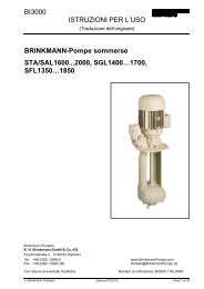
3.3 Installing the drive control integrated in the motor<br />
3.3.1 Power connection<br />
L1 L2 L3 PE B+ B-<br />
Fig. 3: Power connection<br />
� Unscrew the four bolts from the housing cover of the drive control and<br />
remove the cover.<br />
� Guide the power cord through the cable connection and connect the<br />
phases to contacts L1, L2, L3 and the ground cable to the PE contact of<br />
the connection terminal. The cable provides strain relief, and the PE<br />
connection line has to be connected in a leading fashion (considerably<br />
longer).<br />
If a brake resistor is connected, screened and doubly<br />
insulated lines must be used.<br />
Terminal<br />
no.<br />
Designation Configuration<br />
1 L1 Mains phase 1<br />
2 L2 Mains phase 2<br />
3 L3 Mains phase 3<br />
4 PE Ground cable<br />
Tab. 2: Terminal configuration X1<br />
20 Operating manual <strong>FKO</strong>
3.3.2 Connections for brake resistor<br />
Terminal<br />
no.<br />
Designation Configuration<br />
Installation<br />
1 B+ Connection for brake resistor (+)<br />
2 B– Connection for brake resistor (-)<br />
Tab. 3: Optional terminal configuration for brake chopper<br />
3.3.3 Control connections<br />
Fig. 4: Control connections<br />
ATTENTION<br />
Danger of external signals being coupled in.<br />
Use only screened control lines.<br />
� Guide the required control lines into the housing through the cable screw<br />
connections.<br />
� Connect the control lines according to the figure and/or table. Use<br />
screened control lines.<br />
� Place the cover on the housing of the drive control and bolt it (torque:<br />
2.0 Nm) tight.<br />
Operating manual <strong>FKO</strong> 21
Installation<br />
Terminal<br />
no.<br />
Designation Configuration<br />
1 24 V In ext. power supply<br />
2 GND (ground) Mass<br />
3 24 V Out int. power supply<br />
4 GND (ground) Mass<br />
5 24 V Out int. power supply<br />
6 Dig. In 1 Target value release<br />
(parameter 1,131)<br />
7 Dig. In 2 Free (not allocated)<br />
8 Dig. In 3 Free (not allocated)<br />
9 Dig. In 4 Error reset<br />
(parameter 1,180)<br />
10 En-HW (release) Hardware release<br />
11 Dig. Out 1 Fault message<br />
(parameter 4,150)<br />
12 Dig. Out 2 Free (not allocated)<br />
13 A. Out 0 ... 20 mA Actual frequency<br />
(parameter 4,100)<br />
14 10 V Out for ext. voltage divider<br />
15 A. Out 0 ... 10 V Actual frequency<br />
(parameter 4,100)<br />
16 A GND (ground 10 V) Mass<br />
17 A. In 1 Analogue input 1<br />
18 A GND (ground 10 V) Mass<br />
19 A. In 2 Analogue input 2<br />
20 A GND (ground 10 V) Mass<br />
Tab. 4: Terminal configuration X5<br />
22 Operating manual <strong>FKO</strong>
Terminal<br />
no.<br />
Designation Configuration<br />
1 COM Centre contact relay 1<br />
2 NO Closing contact relay 1<br />
3 NC Opening contact relay 1<br />
Tab. 5: Terminal configuration X6 (relay 1)<br />
Installation<br />
In the factory setting, relay 1 is programmed as “inverter<br />
error (NC)” (parameter 4.190).<br />
Terminal<br />
no.<br />
Designation Configuration<br />
1 COM Centre contact relay 2<br />
2 NO Closing contact relay 2<br />
3 NC Opening contact relay 2<br />
Tab. 6: Terminal configuration X7 (relay 2)<br />
In the factory setting,“operation” is allocated to relay 2<br />
(parameter 4.210).<br />
Operating manual <strong>FKO</strong> 23
Installation<br />
3.3.4 Terminal connection diagram<br />
Fig 5: Connection diagram<br />
The drive control is operational after the 400 V power supply has been<br />
switched on. Alternatively, the drive control can be started up by connecting<br />
an external 24 V power supply.<br />
The settings required for this are described in the “System parameters”<br />
chapter. A detailed description of the functions of the drive control can be<br />
found in the parameter description.<br />
3.4 Installing the wall-mounted drive control<br />
3.4.1 Suitable installation location for wall mounting<br />
� Ensure that the installation location for a <strong>FKO</strong> wall mounting meets the<br />
following conditions:<br />
– The drive control has to be mounted on an even and fixed surface.<br />
– The drive control may only be mounted on non-flammable bases.<br />
– There must be a minimum of 20 cm clearance all around the drive<br />
control to ensure free convection.<br />
24 Operating manual <strong>FKO</strong>
Installation<br />
The following figure shows the assembly dimensions and the free spaces<br />
required for installing the drive control.<br />
Fig. 6: Minimum clearances<br />
For the "wall mounting" version, the line length between the motor and <strong>FKO</strong><br />
may not exceed 5 m. A screened cable with the required cross-section<br />
must be used. There must be a PE connection (underneath the wall<br />
mounting's terminal board)!<br />
Operating manual <strong>FKO</strong> 25
Installation<br />
3.4.2 Mechanical installation<br />
Fig. 7: Wiring on the motor connection box<br />
� Open the motor connection box.<br />
ATTENTION<br />
Depending on the required motor voltage, the star or triangle connection<br />
must be made in the motor connection box!<br />
� Use a suitable EMC screw connection to attach the screened cable to<br />
the motor connection box and ensure that the screening contact is in<br />
order (large surface).<br />
� Connecting a PE connection in the motor connection box is mandatory.<br />
� Close the motor connection box.<br />
26 Operating manual <strong>FKO</strong>
Fig. 8: Fastening the adapter plate to a wall<br />
DANGER!<br />
The drive control may not be installed without an adapter plate!<br />
Installation<br />
� Find a position that meets the required ambient conditions as described<br />
in the "Installation requirements" section.<br />
� To achieve optimum self-convection of the drive control, ensure that the<br />
(EMC) screw connection is facing upwards when installing.<br />
� Without any additional ventilation for the <strong>FKO</strong> (optional for BG C), it is<br />
only permitted to be installed vertically.<br />
Operating manual <strong>FKO</strong> 27
Installation<br />
Fig. 9: Wiring<br />
1. Release the screw (1) to remove the contact plate from the adapter<br />
plate. The (M6) PE connection (3) is underneath this contact plate.<br />
2. Guide the connection cable from the motor to the adapter plate through<br />
the integrated EMC screw connection.<br />
3. This connection has to be made to the same ground potential of the<br />
motor. The cross-section of the equipotential bonding line must<br />
correspond to at least the cross-section of the power cord.<br />
4. Reattach the contact plate using the screw (1).<br />
28 Operating manual <strong>FKO</strong>
Installation<br />
5. Wire the motor cable to contacts U, V, W (and star point in some cases)<br />
in the connection terminal, as described in the "Basic connection<br />
versions" chapter. Use cable shoes (M5) to do this.<br />
6. Before connecting an available motor PTC to the T1 and T2 terminals,<br />
remove the preassembled short-circuit bridge (2).<br />
The motor PTC is potential-free after connecting the <strong>FKO</strong>, therefore it<br />
must be connected using a separate motor lead.<br />
Replace the dummy screw with a suitable standard screw connection<br />
and guide both ends to T1 and T2.<br />
Fig. 10: Attaching the drive control<br />
7. Position the drive control (1) on the adapter plate (2) so that the collar of<br />
the adapter dips into the opening on the floor of the cooling element.<br />
8. Fasten the control unit to the adapter plate with the help of the screws<br />
(3) provided (torque: 4.0 Nm).<br />
Operating manual <strong>FKO</strong> 29
Installation<br />
3.4.3 Power connection<br />
The power connections should be designed as described in section 3.3.2 ff.<br />
"Installing the drive control integrated in the motor".<br />
3.4.4 Brake chopper<br />
The brake connections should be designed as described in section 3.3.3 ff.<br />
"Installing the drive control integrated in the motor".<br />
3.4.5 Control connections<br />
The control connections should be designed as described in section 3.3.4<br />
ff. "Installing the drive control integrated in the motor".<br />
30 Operating manual <strong>FKO</strong>
4 Commissioning<br />
4.1 Safety instructions during commissioning<br />
Commissioning<br />
ATTENTION!<br />
Danger of damage<br />
If the notes are not observed, the drive control could be damaged and<br />
destroyed during subsequent start-up.<br />
� Commissioning may only be performed by qualified staff. Safety<br />
precautions and warnings must always be observed.<br />
WARNING<br />
Danger of injury<br />
Non-observance of warnings can result in serious injury or damage.<br />
� Make certain that the power supply provides the correct voltage and is<br />
designed for the required current.<br />
� Use suitable circuit breakers with the prescribed nominal current<br />
between the mains and the drive control.<br />
� Use suitable fuses with appropriate current values between the mains<br />
and the drive control (see technical data).<br />
� The drive control must be grounded with the motor according to<br />
regulations. Non-compliance can result in serious injury.<br />
Operating manual <strong>FKO</strong> 31
Commissioning<br />
4.2 Communication<br />
The drive control can be commissioned in the following ways:<br />
– Using the PC software<br />
Fig. 11: PC software – start screen<br />
– Using MMI<br />
Fig. 12: Manual control unit MMI<br />
<strong>Brinkmann</strong><br />
<strong>Pumps</strong><br />
32 Operating manual <strong>FKO</strong>
4.3 Block diagram<br />
Internal potentiometer<br />
Analogue input 1<br />
Analogue input 2<br />
HMI / PC<br />
Motorized potentiometer<br />
Total AI1 / AI2<br />
PID present reference<br />
Fieldbus<br />
Analogue input 1<br />
Analogue input 2<br />
Digital input 1<br />
Digital input 2<br />
Digital input 3<br />
Digital input 4<br />
Analogue input 1<br />
Analogue input 2<br />
Fieldbus<br />
Autostart<br />
Revers Speed<br />
direction<br />
X(-1)<br />
1.150<br />
Reference<br />
channel<br />
1.130<br />
PID feedback<br />
3.060<br />
Enable software<br />
f<br />
1.131<br />
Low-/ Highspeed<br />
t<br />
1.020 1.021<br />
Control<br />
mode<br />
1.100<br />
Motor current limit<br />
I<br />
t<br />
5.070 5.071<br />
Fig. 13: General structure of target value generation<br />
Ramps<br />
t<br />
1.051 1.050<br />
1.053 1.052<br />
<strong>Frequency</strong><br />
control mode<br />
PID process<br />
control<br />
Preset speed<br />
mode<br />
Commissioning<br />
Motor<br />
control<br />
Operating manual <strong>FKO</strong> 33<br />
f<br />
Control modes<br />
Reference<br />
speed
Commissioning<br />
4.4 Start-up steps<br />
Parameterising is possible prior to installation.<br />
Parameterisation can be performed before the drive<br />
control is installed in the engine.<br />
The drive control has a 24 V low-voltage input for this<br />
purpose, which can supply the electric system without<br />
requiring mains power.<br />
The start-up can be performed using a PC communication cable USB at<br />
plug M12 with integrated interface <strong>converter</strong> RS485/RS232 (article no.<br />
6UMZU0AA-K07324) or using the <strong>FKO</strong> manual control unit MMI with<br />
connection cable RJ11 at plug M12 (article no. 6UMZU0AA-K07323).<br />
Start-up using the PC:<br />
� Install the <strong>FKO</strong>pc software (you can obtain programming software from<br />
BRINKMANN free of charge).<br />
� Connect the PC to the M12 plug M1 with the optional connection cable.<br />
� Load or determine the motor data record (parameters 33,030 to 33,050);<br />
it may be necessary to optimise the speed control (parameters 34,100 to<br />
34,101).<br />
� Make the application settings (ramps, inputs, outputs, target values etc.).<br />
� Optional: Define an access level (1 – MMI, 2 – user, 3 – manufacturer).<br />
Please see also the quickstart guide in chapter 9.5.<br />
In order to ensure an ideal operating structure for the PC software, the<br />
parameters are classified into different access levels. There are the<br />
following levels:<br />
1. Manual control unit: – the drive control is programmed using the manual<br />
control unit<br />
2. User: – the basic parameters can be programmed into the drive control<br />
using the PC software<br />
3. Manufacturer: – an extended selection of parameters can be<br />
programmed into the drive control using the PC software<br />
34 Operating manual <strong>FKO</strong>
5 Parameters<br />
Parameters<br />
This chapter contains the following:<br />
– An introduction to the parameters<br />
– An overview of the most important start-up and operation parameters<br />
5.1 Safety instructions for dealing with parameters<br />
WARNING<br />
Danger of injury due to restarting motors.<br />
Non-observance can result in serious injury or damage.<br />
� Certain parameter settings and the changing of parameter settings<br />
during operation can result in the <strong>FKO</strong> drive control restarting<br />
automatically after the supply voltage has failed, or in undesirable<br />
changes in the operating behaviour.<br />
If parameters are changed while the device is in<br />
operation, it may take a few seconds until the effect<br />
becomes noticeable.<br />
5.2 General information on parameters<br />
5.2.1 Explanation of operating modes<br />
The operating mode is the instance in which the reference is generated. In<br />
case of the frequency setting mode, this is a simple conversion of the raw<br />
input reference into a rotation speed reference; in the case of PID process<br />
control, the reference and feedback are compared and then a control to a<br />
specific process variable is performed.<br />
<strong>Frequency</strong> setting mode:<br />
The references from the “reference channel” (1,130) are rescaled into<br />
frequency reference. 0% is the “low speed” (1,020), 100% is the “high<br />
speed” (1,021).<br />
The plus or minus sign of the reference is the decisive factor in rescaling.<br />
Operating manual <strong>FKO</strong> 35
Parameters<br />
PID process control:<br />
The reference for the PID process control is read in percentage steps as in<br />
the “frequency setting mode”. 100% corresponds to the working range of<br />
the connected sensor, which is read in from the active channel (selected by<br />
the “PID feedback”).<br />
Depending on the control difference, a rotation speed value is output to the<br />
control output with the help of the amplification factors for the propotional<br />
gain (3,050), integral gain (3,051) and derivative gain (3,052). In order to<br />
prevent the integral share from increasing limitlessly in case of<br />
uncontrollable control differences, this value is limited to a specific set<br />
value (corresponding to the “maximum frequency” (1,021)).<br />
PID inverse:<br />
The PID feedback can be inverted using the 3.061 parameter. The feedback<br />
is imported inversely, i.e. 0 V…10 V correspond internally to 100%…0%.<br />
Please note that the reference must also be defined inversely.<br />
An example:<br />
A sensor with an analogue output signal of (0 V…10 V) is to operate as the<br />
source of the feedback channel (at AIx). At an output variable of 7 V (70%),<br />
this is to be regulated inversely. The internal feedback then corresponds to<br />
100% – 70% = 30%. Accordingly, the specified reference is 30%.<br />
Reference<br />
channel<br />
1.130<br />
PID<br />
feedback<br />
3.060<br />
Inverted<br />
3.061<br />
Fig. 14: PID process control<br />
PID process controller operating mode<br />
-<br />
KP<br />
3.050<br />
KI<br />
3.051<br />
KD<br />
3.052<br />
Limitation I<br />
part<br />
y<br />
i<br />
y<br />
imax +<br />
36 Operating manual <strong>FKO</strong><br />
t<br />
3.070 3.071<br />
PID<br />
stand-by<br />
function<br />
0<br />
<strong>Frequency</strong><br />
reference mode
Stand-by function in PID process control:<br />
Parameters<br />
This function can provide energy savings in applications such as booster<br />
stations where PID process control is used to control to a specific process<br />
value and the pump has to run on a “minimum frequency” (1,020). As the<br />
inverter can reduce the rotation speed of the pump in normal operation<br />
when the process variable is reducing, but is never able to fall below the<br />
“minimum frequency” (1,020), this provides the opportunity of stopping the<br />
engine if it is running during a waiting time, the “PID stand-by time” (3,070)<br />
with the “minimum frequency” (1,020).<br />
Once the reference diverges from the set % value, the “PID stand-by<br />
hysteresis” (3,071), the control (the motor) is started again.<br />
Fig. 15: Stand-by function in PID process control<br />
Operating manual <strong>FKO</strong> 37
Parameters<br />
Preset speed:<br />
In this operating mode, preset speed references are transferred to the<br />
motor control. There are 7 preset speeds (2,051 to 2,057) that are BCD<br />
coded and attached fixedly to digital inputs 1 to 3. These seven preset<br />
speeds can be released in three groups via the “preset speed mode”<br />
(2,050) parameter:<br />
0 = preset speed 1, 1 = preset speed 1 to 3, 2 = preset speed 1 to 7.<br />
DI 3 DI 2 DI 1 Selection Parameters Presetting<br />
0 0 0 Min. frequency 1.020 0 Hz<br />
0 0 1 preset speed 1 2.051 10 Hz<br />
0 1 0 preset speed 2 2.052 20 Hz<br />
0 1 1 preset speed 3 2.053 30 Hz<br />
1 0 0 preset speed 4 2.054 35 Hz<br />
1 0 1 preset speed 5 2.055 40 Hz<br />
1 1 0 preset speed 6 2.056 45 Hz<br />
1 1 1 preset speed 7 2.057 50 Hz<br />
Tab. 7: Logic table of fixed frequencies<br />
38 Operating manual <strong>FKO</strong>
5.2.2 Structure of the parameter tables<br />
Fig 16: Example for a parameter table<br />
Parameters<br />
Key<br />
1 Parameter numbers 6 Unit<br />
2 Description in the parameter manual on 7 Field for entering an own value<br />
page ...<br />
3 Parameter name 8 Explanation of the parameter<br />
4 Transfer status<br />
9 There are further parameters that relate<br />
0 = switch drive control off and on for<br />
to these parameters<br />
transfer<br />
1 = set hardware release again<br />
2 = during operation<br />
5 Value range (from – to – factory setting)<br />
Operating manual <strong>FKO</strong> 39
Parameters<br />
5.3 Application parameters<br />
5.3.1 Basic parameters<br />
1.020 Low speed Unit: Hz<br />
Relationship to<br />
parameter:<br />
1,150<br />
3,070<br />
Parameter manual:<br />
p. xy<br />
Transfer status:<br />
40 Operating manual <strong>FKO</strong><br />
2<br />
min: 0 own value (to<br />
be entered!)<br />
max.: 400<br />
def.: 0<br />
The low speed is the frequency provided by the drive control as soon as it<br />
released and no additional target value is pending.<br />
This frequency is not reached if<br />
a) acceleration is carried out while the drive is not moving.<br />
b) the frequency inverter is blocked. The frequency is then reduced to 0 Hz<br />
before it is blocked.<br />
c) the frequency inverter reverses (1,150). The revolving field is reversed<br />
at 0 Hz.<br />
d) the stand-by function (3,070) is active.<br />
1.021 High speed Unit: Hz<br />
Relationship to<br />
parameter:<br />
1,050<br />
1,051<br />
Parameter manual:<br />
p. xy<br />
Transfer status:<br />
2<br />
min: 5 own value (to<br />
be entered!)<br />
max.: 400<br />
def.: 50<br />
The high speed is the frequency produced by the inverter in dependence<br />
on the reference.<br />
1.050 Deceleration 1: Unit: s<br />
Relationship to<br />
parameter:<br />
1,021<br />
1,054<br />
Parameter manual:<br />
p. xy<br />
Transfer status:<br />
2<br />
min: 0,1 own value (to<br />
be entered!)<br />
max.: 1000<br />
def.: 5<br />
Deceleration 1 is the time that the inverter takes to brake to 0 Hz from the<br />
high speed (1,021).<br />
If the set deceleration time cannot be reached, the fastest possible<br />
deceleration time is implemented.
1.051 Acceleration 1 Unit: s<br />
Relationship to<br />
parameter:<br />
1,021<br />
1,054<br />
Parameter manual:<br />
p. xy<br />
Transfer status:<br />
Parameters<br />
Operating manual <strong>FKO</strong> 41<br />
2<br />
min: 0,1 own value (to<br />
be entered!)<br />
max.: 1000<br />
def.: 5<br />
Acceleration 1 is the time that the inverter takes to speed up from 0 Hz to<br />
the high speed.<br />
The acceleration time can be increased through certain circumstances,<br />
e.g. if the drive control is overloaded.<br />
1.052 Deceleration 2 Unit: s<br />
Relationship to<br />
parameter:<br />
1,021<br />
1,054<br />
Parameter manual:<br />
p. xy<br />
Transfer status:<br />
2<br />
min: 0,1 own value<br />
(to be entered!)<br />
max.: 1,000<br />
def.: 10<br />
Deceleration 2 is the time that the inverter takes to brake to 0 Hz from the<br />
high speed (1,021).<br />
If the set deceleration time cannot be reached, the fastest possible<br />
deceleration time is implemented.<br />
1.053 Acceleration 2 Unit: s<br />
Relationship to<br />
parameter:<br />
1,021<br />
1,054<br />
Parameter manual:<br />
p. xy<br />
Transfer status:<br />
2<br />
min: 0,1 own value<br />
(to be entered!)<br />
max.: 1,000<br />
def.: 10<br />
Acceleration 2 is the time that the inverter takes to speed up from 0 Hz to<br />
the high speed.<br />
The acceleration time can be increased through certain circumstances,<br />
e.g. if the drive control is overloaded.
Parameters<br />
1.054 Ramp section Unit: integer<br />
Relationship to<br />
parameter:<br />
1,050 to 1,053<br />
Parameter manual:<br />
p. xy<br />
Selection of used ramp pair<br />
Transfer status:<br />
42 Operating manual <strong>FKO</strong><br />
2<br />
min: 0 own value (to<br />
be entered!)<br />
max.: 6<br />
def.: 0<br />
0 = deceleration 1 (1.050) / acceleration 1 (1.051)<br />
1 = deceleration 2 (1.052) / acceleration 2 (1.053)<br />
2 = digital input 1 (false = ramp pair 1 / True = ramp pair 2)<br />
3 = digital input 2 (false = ramp pair 1 / true = ramp pair 2)<br />
4 = digital input 3 (false = ramp pair 1 / true = ramp pair 2)<br />
5 = digital input 4 (false = ramp pair 1 / true = ramp pair 2)<br />
6 = <strong>FKO</strong> Soft-PLC<br />
1.100 Control mode Unit: integer<br />
Relationship to<br />
parameter:<br />
1,130<br />
1,131<br />
2,051 to 2,057<br />
3,050 to 3,071<br />
Parameter manual:<br />
p. xy<br />
Selecting the operating mode.<br />
Transfer status:<br />
2<br />
min: 0 own value (to<br />
be entered!)<br />
max.: 4<br />
def.: 0<br />
After SW release (1,131) and hardware release, the drive control runs as<br />
follows:<br />
0 = frequency control mode, with the target value of the selected reference<br />
channel (1,130)<br />
1 = PID process control, with the target value of the PID process control<br />
(3,050–3,071)<br />
2 = preset speed mode, with the frequencies specified by parameters<br />
2,051–2,057<br />
3 = selection from <strong>FKO</strong> Soft-PLC
1.130 Reference channel Unit: integer<br />
Relationship to<br />
parameter:<br />
3,062 to 3,069<br />
Parameter manual:<br />
p. xy<br />
Transfer status:<br />
Parameters<br />
Operating manual <strong>FKO</strong> 43<br />
2<br />
min: 0 own value (to<br />
be entered!)<br />
max.: 10<br />
def.: 0<br />
Determines the source from where the reference is to be read.<br />
0 = internal potentiometer<br />
1 = analogue input 1<br />
2 = analogue input 2<br />
3 = MMI/PC<br />
6 = motorizes potentiometer<br />
7= total analogue inputs 1 and 2<br />
8 = PID present reference mode (3,062)<br />
9 = fieldbus<br />
10 = reference from <strong>FKO</strong> Soft-PLC<br />
1.131 Enable software Unit: integer<br />
Relationship to<br />
parameter:<br />
1,132<br />
1,150<br />
2,050<br />
4,030<br />
4,050<br />
Parameter manual:<br />
p. xy<br />
WARNING<br />
Transfer status:<br />
2<br />
min: 0 own value (to<br />
be entered!)<br />
max.: 11<br />
def.: 0<br />
The motor may start immediately, depending on the change made.<br />
Selection of the source for the control release.<br />
0 = digital input 1<br />
1 = digital input 2<br />
2 = digital input 3<br />
3 = digital input 4<br />
4 = analogue input 1 (has to be selected in parameter 4.030)<br />
5 = analogue input 2 (has to be selected in parameter 4.050)<br />
6 = fieldbus<br />
8 = digital input 1 right / digital input 2 left<br />
1,150 must be set to “0”<br />
9 = autostart:<br />
10 = <strong>FKO</strong> Soft-PLC<br />
11 = preset frequency input (all inputs which are selected in parameter<br />
2,050)<br />
The motor may start immediately if hardware is enabled (En.Hw. Fig. 8)<br />
and a reference have been provided.<br />
This cannot be prevented even with parameter 1,132.
Parameters<br />
1.132 Start protect Unit: integer<br />
Relationship to<br />
parameter:<br />
1,131<br />
Parameter manual:<br />
p. xy<br />
Transfer status:<br />
44 Operating manual <strong>FKO</strong><br />
2<br />
min: 0 own value (to<br />
be entered!)<br />
max.: 1<br />
def.: 1<br />
Selection of the behaviour in response to enable software (parameter<br />
1,131).<br />
No effect if autostart was selected.<br />
0 = immediate start when high signal is received at start input of control<br />
release<br />
1 = start only in case of rising shoulder at start input of control release<br />
2 = digital input 1 (function active at high signal)<br />
3 = digital input 2 (function active at high signal)<br />
4 = digital input 3 (function active at high signal)<br />
5 = digital input 4 (function active at high signal)<br />
1.150 Rotational direction Unit: integer<br />
Relationship to<br />
parameter:<br />
1,131<br />
Parameter manual:<br />
p. xy<br />
Transfer status:<br />
Selecting the rotational direction specification<br />
2<br />
min: 0 own value (to<br />
be entered!)<br />
max.: 7<br />
def.: 0<br />
0 = dependent on target value (depending on the plus or minus sign of the<br />
target value: positive: forward; negative: backwards)<br />
1 = forwards only (rotational direction cannot be changed)<br />
2 = backwards only (rotational direction cannot be changed)<br />
3 = digital input 1 (0 V = forwards, 24 V = backwards)<br />
4 = digital input 2 (0 V = forwards, 24 V = backwards)<br />
5 = digital input 3 (0 V = forwards, 24 V = backwards)<br />
6 = digital input 4 (0 V = forwards, 24 V = backwards)<br />
7 = reference from <strong>FKO</strong> Soft-PLC
1.180 Reset Unit: integer<br />
Relationship to<br />
parameter:<br />
1,181<br />
1,182<br />
Parameter manual:<br />
p. xy<br />
Transfer status:<br />
Selection of the source for error confirmation.<br />
Parameters<br />
Operating manual <strong>FKO</strong> 45<br />
2<br />
min: 0 own value (to<br />
be entered!)<br />
max.: 4<br />
def.: 4<br />
Errors can only be confirmed once the error has been removed.<br />
Some errors can only be confirmed by switching the control off and then on<br />
again,<br />
see list of errors.<br />
Auto-confirmation via parameter 1,181.<br />
0 = no manual confirmation possible<br />
1 = rising shoulder at digital input 1<br />
2 = rising shoulder at digital input 2<br />
3 = rising shoulder at digital input 3<br />
4 = rising shoulder at digital input 4<br />
1.181 Automatic reset Unit: s<br />
Relationship to<br />
parameter:<br />
1,180<br />
1,182<br />
Parameter manual:<br />
p. xy<br />
Transfer status:<br />
2<br />
min: 0 own value (to<br />
be entered!)<br />
max.:1,000,000<br />
def.: 0<br />
Next to the reset function (1,180), an automatic reset can be selected.<br />
0 = no automatic confirmation<br />
> 0 = time for automatic reset of error in seconds<br />
1.182 Quantity of automatic reset Unit:<br />
Relationship to<br />
parameter:<br />
1,180<br />
1,181<br />
Parameter manual:<br />
p. xy<br />
Transfer status:<br />
2<br />
min: 0 own value (to<br />
be entered!)<br />
max.: 500<br />
def.: 5<br />
Next to the automatic reset (1,181), it is possible to limit the number of<br />
maximum automatic resets here.<br />
0 = no restriction of automatic confirmations<br />
> 0 = number of maximum permitted automatic confirmations
Parameters<br />
5.3.2 Preset speed mode<br />
This mode has to be selected in parameter 1,100,<br />
see also the section on selecting the operating mode<br />
2.050 Preset speed mode Unit: integer<br />
Relationship to<br />
parameter:<br />
1,100<br />
2,051 to 2,057<br />
Parameter manual:<br />
p. xy<br />
Transfer status:<br />
46 Operating manual <strong>FKO</strong><br />
2<br />
min: 0 own value (to<br />
be entered!)<br />
max.: 2<br />
def.: 2<br />
Selection of the digital inputs used for the preset speeds<br />
0 = Digital In 1 (preset speed 1) (2,051)<br />
1 = Digital In 1, 2 (preset speeds 1 - 3) (2,051 to 2,053)<br />
2 = Digital In 1, 2, 3 (preset speeds 1 - 7) (2,051 to 2,057)<br />
2,051 to 2,057 Preset speed Unit: Hz<br />
Relationship to<br />
parameter:<br />
1,020<br />
1,021<br />
1,100<br />
1,150<br />
2,050<br />
Parameter manual:<br />
p. xy<br />
Transfer status:<br />
2<br />
min: -400 own value (to<br />
be entered!)<br />
max.: +400<br />
def.: 0<br />
The frequencies that are to be put out at the digital inputs 1 - 3 specified in<br />
parameter 2,050 in dependence on the switching patterns.<br />
See chapter 5.2.1 on preset speeds.
5.3.3 Motorized potentiometer<br />
Parameters<br />
This mode must be selected in the parameter 1.130. This function can be<br />
used as a source of target values for the frequency setting mode as well as<br />
for the PID process controller.<br />
2.150 MOP digital Input unit: integer<br />
Relationship to<br />
Parameter:<br />
1,130<br />
4,030<br />
4,050<br />
Parameter manual:<br />
p. xy<br />
Transfer status:<br />
Operating manual <strong>FKO</strong> 47<br />
2<br />
min: 0 Own value (to<br />
be entered!)<br />
max.: 7<br />
def.: 3<br />
Selection of the source for increasing and reducing the target value<br />
0 = Digital In 1 + / Digital In 2 -<br />
1 = Digital In 1 + / Digital In 3 -<br />
2 = Digital In 1 + / Digital In 4 -<br />
3 = Digital In 2 + / Digital 3 -<br />
4 = Digital In 2 + / Digital In 4 -<br />
5 = Digital In 3 + / Digital In 4 -<br />
6 = Analogue In 1 + / Analogue In 2 -<br />
(must be selected in parameter 4,030 / 4,050)<br />
7 = reference from customer PLC<br />
2.151 MOP step range Unit: %<br />
Relationship to<br />
parameter:<br />
1.020<br />
1.021<br />
Parameter manual:<br />
p. xy<br />
Transfer status:<br />
2<br />
min: 0 Own value (to<br />
be entered!)<br />
max.: 100<br />
def.: 1<br />
Increments at which the target value changes per keystroke.<br />
2.152 MOP step time Unit: s<br />
Relationship to<br />
parameter:<br />
Parameter manual:<br />
p. xy<br />
Transfer status:<br />
2<br />
min: 0.02 Own value (to<br />
be entered!)<br />
max.: 1000<br />
def.: 0.04<br />
Indicates the time in which the target value totals up for permanent signal.
Parameters<br />
2.153 MOP response time Unit: s<br />
Relationship to<br />
parameter:<br />
Parameter manual:<br />
p. xy<br />
Transfer status:<br />
48 Operating manual <strong>FKO</strong><br />
2<br />
min: 0.02 Own value (to<br />
be entered!)<br />
max.: 1000<br />
def.: 0.3<br />
Indicates the time for which the signal is considered permanent.<br />
2.154 MOP reference memory Unit: integer<br />
Relationship to<br />
parameter:<br />
Parameter manual:<br />
p. xy<br />
Transfer status:<br />
2<br />
min: 0 Own value (to<br />
be entered!)<br />
max.: 1<br />
def.: 0<br />
Defines whether the target value of the motor potentiometer is retained<br />
even after power outage.<br />
0 = deactivated<br />
1 = activated<br />
5.3.4 PID process controller<br />
This mode has to be selected in parameter 1,100,<br />
the target value source has to be selected in parameter 1,130,<br />
see also chapter 5.2.1, “Explanation of operating modes – preset speed”.<br />
3.050 PID proportional gain Unit:<br />
Relationship to<br />
parameter:<br />
1,100<br />
1,130<br />
Parameter manual:<br />
p. xy<br />
Transfer status:<br />
proportional share of PID controller<br />
2<br />
min: 0 own value (to<br />
be entered!)<br />
max.: 100<br />
def.: 1<br />
3.051 PID integral gain Unit: 1/s<br />
Relationship to<br />
parameter:<br />
1,100<br />
1,130<br />
Parameter manual:<br />
p. xy<br />
Transfer status:<br />
integral share of PID controller<br />
2<br />
min: 0 own value (to<br />
be entered!)<br />
max.: 100<br />
def.: 1
3.052 PID derivative gain Unit: s<br />
Relationship to<br />
parameter:<br />
1,100<br />
1,130<br />
Parameter manual:<br />
p. xy<br />
Transfer status:<br />
differential share of PID controller<br />
Parameters<br />
Operating manual <strong>FKO</strong> 49<br />
2<br />
min: 0 own value (to<br />
be entered!)<br />
max.: 100<br />
def.: 0<br />
3.060 PID feedback Unit: integer<br />
Relationship to<br />
parameter:<br />
1,100<br />
1,130<br />
3,061<br />
Parameter manual:<br />
p. xy<br />
Transfer status:<br />
2<br />
min: 0 own value (to<br />
be entered!)<br />
max.: 3<br />
def.: 0<br />
Selection of the input source from which the feedback for the PID process<br />
controller is imported:<br />
0 = analogue input1<br />
1 = analogue input2<br />
3.061 PID inverted Unit: integer<br />
Relationship to<br />
parameter:<br />
3,060<br />
Parameter manual:<br />
p. xy<br />
Transfer status:<br />
2<br />
min: 0 own value (to<br />
be entered!)<br />
max.: 1<br />
def.: 0<br />
The source of the feedback (parameter 3,060) is inverted<br />
0 = disable<br />
1 = enable<br />
3.062 to 3.068 PID present reference Unit: %<br />
Relationship to<br />
parameter:<br />
1,130<br />
3,069<br />
Parameter manual:<br />
p. xy<br />
Transfer status:<br />
2<br />
min: 0 own value (to<br />
be entered!)<br />
max.: 100<br />
def.: 0<br />
The PID present reference depending on the switching patterns are to be<br />
issued at the digital inputs 1 – 3 specified in parameter 3,069 (has to be<br />
selected in parameter 1,130).
Parameters<br />
3.069 PID pesent mode Unit: integer<br />
Relationship to<br />
parameter:<br />
1,100<br />
3,062 to 3,068<br />
Parameter manual:<br />
p. xy<br />
Transfer status:<br />
50 Operating manual <strong>FKO</strong><br />
2<br />
min: 0 own value (to<br />
be entered!)<br />
max.: 2<br />
def.: 0<br />
Selection of the digital inputs used for fixed frequencies<br />
0 = Digital In 1 (PID present reference 1) (3,062)<br />
1 = Digital In 1, 2 (PID present references 1 – 3) (3,062 to 3,064)<br />
2 = Digital In 1, 2, 3 (PID present references 1 – 7) (3,062 to<br />
3,068)<br />
3.070 PID stand-by time Unit: s<br />
Relationship to<br />
parameter:<br />
1,020<br />
Parameter manual:<br />
S. xy<br />
Transfer status:<br />
2<br />
min: 0 own value (to<br />
be entered!)<br />
max.: 10000<br />
def.: 0<br />
If the drive control operates the set time with the low speed (parameter<br />
1,020), the motor is stopped (0 Hz), see also Chapter 5.2.1, “PID process<br />
control”<br />
0 = disable<br />
> 0 = waiting time until stand-by function is enabled<br />
3.071 PID stand-by hysteresis Unit: %<br />
Relationship to<br />
parameter:<br />
3,060<br />
Parameter manual:<br />
p. xy<br />
Transfer status:<br />
2<br />
min: 0 own value (to<br />
be entered!)<br />
max.: 50<br />
def.: 0<br />
Condition for waking up the PID controller from stand-by.<br />
Once the control difference exceeds the set value in %, the control begins<br />
again, see also “Control mode (parameter 1,100) – PID controller”.
5.3.5 Analogue inputs<br />
For analogue inputs 1 and 2 (Alx display Al1/Al2)<br />
4.020/4.050 Alx reference type Unit: integer<br />
Relationship to<br />
parameter:<br />
Parameter manual:<br />
p. xy<br />
Transfer status:<br />
Function of analogue inputs 1/2:<br />
1 = voltage input<br />
2 = current input<br />
Parameters<br />
Operating manual <strong>FKO</strong> 51<br />
2<br />
min: 0 own value (to<br />
be entered!)<br />
max.: 1<br />
def.: 1<br />
4.021/4.051 Alx minimum input Unit: %<br />
Relationship to<br />
parameter:<br />
Parameter manual:<br />
p. xy<br />
Transfer status:<br />
2<br />
min: 0 own value (to<br />
be entered!)<br />
max.: 100<br />
def.: 0<br />
Specifies the minimum value of the analogue inputs as a percentage of the<br />
final area value.<br />
Example: 0…10 V or 0…20 mA = 0%…100%<br />
2…10 V or 4…20 mA = 20%…100%<br />
4.022/4.052 Alx maximum input Unit: %<br />
Relationship to<br />
parameter:<br />
Parameter manual:<br />
p. xy<br />
Transfer status:<br />
2<br />
min: 0 own value (to<br />
be entered!)<br />
max.: 100<br />
def.: 100<br />
Specifies the maximum value of the analogue inputs as a percentage of<br />
the final area value.<br />
Example: 0…10 V or 0…20 mA = 0%…100%<br />
2…10 V or 4…20 mA = 20%…100%<br />
4.023/4.053 Alx dead time Unit: %<br />
Relationship to<br />
parameter:<br />
Parameter manual:<br />
p. xy<br />
Transfer status:<br />
2<br />
min: 0 own value (to<br />
be entered!)<br />
max.: 100<br />
def.: 0<br />
Dead time in percentage of the final area value of the analogue inputs.
Parameters<br />
4.024/4.054 Alx filter time Unit: s<br />
Relationship to<br />
parameter:<br />
Parameter manual:<br />
p. xy<br />
Transfer status:<br />
Filter time of analogue inputs in seconds.<br />
52 Operating manual <strong>FKO</strong><br />
2<br />
min: 0.02 own value (to<br />
be entered!)<br />
max.: 1.00<br />
def.: 0<br />
4.030/4.060 AIx function Unit: integer<br />
Relationship to<br />
parameter:<br />
Parameter manual:<br />
p. xy<br />
Transfer status:<br />
Function of analogue inputs 1/2<br />
0 = analogue input<br />
1 = digital input<br />
2<br />
min: 0 own value (to<br />
be entered!)<br />
max.: 1<br />
def.: 0<br />
4.033/4.063 Alx physical unit Unit:<br />
Relationship to<br />
parameter:<br />
4,034/4,064<br />
4,035/4,065<br />
min: 0 own value (to<br />
Parameter manual: Transfer status:<br />
be entered!)<br />
max.: 10<br />
p. xy<br />
2<br />
def.: 0<br />
Selection of different physical values to be displayed.<br />
0 = %<br />
1 = bar<br />
2 = mbar<br />
3 = psi<br />
4 = Pa<br />
5 = m 3 /h<br />
6 = l/min<br />
7 = °C<br />
8 = °F<br />
9 = m<br />
10 = mm
4.034/4.064 Alx physical minimum Unit:<br />
Relationship to<br />
parameter:<br />
4,033/4,063<br />
4,035/4,065<br />
Parameter manual:<br />
p. xy<br />
Transfer status:<br />
Parameters<br />
Operating manual <strong>FKO</strong> 53<br />
2<br />
min:-10,000 own value (to<br />
be entered!)<br />
max.:+10,000<br />
def.: 0<br />
Selection of the lower limit of a physical value to be displayed.<br />
4.035/4.065 Alx physical maximum Unit:<br />
Relationship to<br />
parameter:<br />
4,033/4,063<br />
4,034/4,064<br />
5.3.6 Digital inputs<br />
Parameter manual:<br />
p. xy<br />
Transfer status:<br />
2<br />
min:-10,000 own value (to<br />
be entered!)<br />
max.:+10,000<br />
def.: 100<br />
Selection of the upper limit of a physical value to be displayed.<br />
4.110 to 4.113 DIx inverted Unit: integer<br />
Relationship to<br />
parameter:<br />
Parameter manual:<br />
p. xy<br />
Transfer status:<br />
2<br />
min: 0 own value (to<br />
be entered!)<br />
max.: 1<br />
def.: 0<br />
This parameter can be used to invert the digital input.<br />
0 = disable<br />
1 = enable
Parameters<br />
5.3.7 Analogue output<br />
4.100 AO1 function Unit: integer<br />
Relationship to<br />
parameter:<br />
4,101<br />
4,102<br />
Parameter manual:<br />
p. xy<br />
Transfer status:<br />
54 Operating manual <strong>FKO</strong><br />
2<br />
min: 0 own value (to<br />
be entered!)<br />
max.: 40<br />
def.: 0<br />
Selection of the process value that is output at the analogue output.<br />
The standardisation (4,101/4,102) has to be adapted, depending on the<br />
selected process value.<br />
0 = no signal<br />
1 = intermediate circuit voltage<br />
2 = supply voltage<br />
3 = motor voltage<br />
4 = motor current<br />
5 = actual frequency<br />
6 = rotation speed measured externally by speed sensor (if available)<br />
7 = current angle or position (if available)<br />
8 = IGBT temperature<br />
9 = interior temperature<br />
10 = analogue input1<br />
11 = analogue input2<br />
12 = target frequency<br />
13 = motor power<br />
14 = torque<br />
15 = field bus<br />
4.101 AO1 minimum output Unit:<br />
Relationship to<br />
parameter:<br />
4,100<br />
Parameter manual:<br />
p. xy<br />
Transfer status:<br />
2<br />
min:-10,000,000 own value (to<br />
be entered!)<br />
max.:+1,000,00<br />
0<br />
def.: 0<br />
Describes which area is to be resolved to the 0-10 V output voltage or the<br />
0-20 mA output current.<br />
4.102 AO1 maximum output Unit:<br />
Relationship to<br />
parameter:<br />
4,100<br />
Parameter manual:<br />
p. xy<br />
Transfer status:<br />
2<br />
min: 0 own value (to<br />
be entered!)<br />
max.:+1,000,00<br />
0<br />
def.: 0<br />
Describes which area is to be resolved to the 0-10 V output voltage or the<br />
0-20 mA output current.
5.3.8 Digital outputs<br />
For digital outputs 1 and 2 (DOx display DO1/DO2)<br />
4.150/4.170 DOx function Unit: integer<br />
Relationship to<br />
parameter:<br />
4,151/4,171<br />
4,152/4,172<br />
Parameter manual:<br />
p. xy<br />
Transfer status:<br />
Parameters<br />
Operating manual <strong>FKO</strong> 55<br />
2<br />
min: 0 own value (to<br />
be entered!)<br />
max.: 50<br />
def.: 0<br />
Selection of the process value to which the output should switch.<br />
0 = not allocated / <strong>FKO</strong> Soft-PLC<br />
1= intermediate circuit voltage<br />
2= supply voltage<br />
3= motor voltage<br />
4= motor current<br />
5= actual frequency<br />
6= –<br />
7= –<br />
8= IGBT temperature<br />
9= interior temperature<br />
10= error (NO)<br />
11= inverted error (NC)<br />
12= final release levels<br />
13= digital input1<br />
14= digital input 2<br />
15= digital input 3<br />
16= digital input 4<br />
17= ready for operation<br />
18= ready<br />
19= operation<br />
20= ready for operation + ready<br />
21= ready for operation + ready + operation<br />
22= ready + operation<br />
23 = motor power<br />
24 = torque<br />
25 = field bus<br />
50 = motor current limit active<br />
4.151/4.171 DOx on Unit:<br />
Relationship to<br />
parameter:<br />
4,150/4,170<br />
Parameter manual:<br />
p. xy<br />
Transfer status:<br />
2<br />
min: 0 own value (to<br />
be entered!)<br />
max.:1,000,000<br />
def.: 0<br />
If the set process value exceeds the switch-on limit, the output is set to 1.
Parameters<br />
4.152/4.172 DOx off Unit:<br />
Relationship to<br />
parameter:<br />
4,150/4,170<br />
Parameter manual:<br />
p. xy<br />
Transfer status:<br />
56 Operating manual <strong>FKO</strong><br />
2<br />
min: 0 own value (to<br />
be entered!)<br />
max.:1,000,000<br />
def.: 0<br />
If the set process value exceeds the switch-on limit, the output is set to 1.<br />
5.3.9 Relay<br />
For relays 1 and 2 (Rel.x – display Rel. 1/Rel. 2)<br />
4.190/4.210 Rel.x function Unit: integer<br />
Relationship to<br />
parameter:<br />
4,191/4,211<br />
4,192/4,212<br />
Parameter manual:<br />
p. xy<br />
Transfer status:<br />
2<br />
min: 0 own value (to<br />
be entered!)<br />
max.: 500<br />
def.: 0<br />
Selection of the process value to which the output should switch.<br />
0= not allocated / <strong>FKO</strong> Soft-PLC<br />
1= intermediate circuit voltage<br />
2= supply voltage<br />
3= motor voltage<br />
4= motor current<br />
5= actual frequency<br />
6= –<br />
7= –<br />
8= IGBT temperature<br />
9= interior temperature<br />
10= error (NO)<br />
11= inverted error (NC)<br />
12= final release levels<br />
13= digital input1<br />
14= digital input 2<br />
15= digital input 3<br />
16= digital input 4<br />
17= ready for operation<br />
18= ready<br />
19= operation<br />
20= ready for operation + ready<br />
21= ready for operation + ready + operation<br />
22= ready + operation<br />
23 = motor power<br />
24 = torque<br />
25 = field bus<br />
50 = motor current limit active
4.191/4.211 Rel.x on Unit:<br />
Relationship to<br />
parameter:<br />
4,190/4,210<br />
Parameter manual:<br />
p. xy<br />
Transfer status:<br />
Parameters<br />
Operating manual <strong>FKO</strong> 57<br />
2<br />
min: 0 own value (to<br />
be entered!)<br />
max.:1000000<br />
def.: 0<br />
If the set process value exceeds the switch-on limit, the output is set to 1.<br />
4.192/4.212 Rel.x off Unit:<br />
Relationship to<br />
parameter:<br />
4,190/4,210<br />
Parameter manual:<br />
p. xy<br />
Transfer status:<br />
2<br />
min: 0 own value (to<br />
be entered!)<br />
max.:1000000<br />
def.: 0<br />
If the set process value exceeds the switch-on limit, the output is set to 1.<br />
4.193/4.213 Rel.x on delay Unit:<br />
Relationship to<br />
parameter:<br />
4,194/4,214<br />
Parameter manual:<br />
p. xy<br />
Transfer status:<br />
Specifies the length of the switch-on delay.<br />
2<br />
min: 0 own value (to<br />
be entered!)<br />
max.: 99<br />
def.: 0<br />
4.194/4.214 Rel.x off delay Unit:<br />
Relationship to<br />
parameter:<br />
4,193/4,213<br />
Parameter manual:<br />
p. xy<br />
Transfer status:<br />
Specifies the length of the switch-off delay.<br />
2<br />
min: 0 own value (to<br />
be entered!)<br />
max.: 99<br />
def.: 0
Parameters<br />
5.3.10 External fault<br />
5.010/5.011 External fault 1/2 Unit: integer<br />
Relationship to<br />
parameter:<br />
4,110 to 4,113<br />
Parameter manual:<br />
p. xy<br />
Transfer status:<br />
58 Operating manual <strong>FKO</strong><br />
2<br />
min: 0 own value (to<br />
be entered!)<br />
max.: 4<br />
def.: 0<br />
Selection of the source from which an external error can be reported.<br />
0 = disable<br />
1 = digital input 1<br />
2 = digital input 2<br />
3 = digital input 3<br />
4 = digital input 4<br />
5.3.11 Motor current limit<br />
If the selected digital input has a high signal, the inverter switches to error<br />
no. 23/24 external fault 1/2.<br />
Parameters 4,110 to 4,113 DIx inverse can be used to invert the logic of<br />
the digital input.<br />
This function limits the motor current to a parameterised maximum value<br />
after a parameterised current-time surface has been reached.<br />
This motor current limit is monitored at application level and thereby limits<br />
with relatively low dynamics. This has to be considered when selecting this<br />
function.<br />
The maximum value is determined using the “motor current limit in %”<br />
parameter (5,070). This is given in percent and relates to the nominal motor<br />
current specified in the “motor current” type plate data (33,031).<br />
The maximum current-time surface is calculated from the product of the<br />
“motor current limit in s” parameter (5,071) and the fixed over-current of<br />
50% of the required motor current limit.<br />
As soon as this current-time surface is exceeded, the motor current is<br />
restricted to the limit value by reducing the rotation speed. If the output<br />
current of the drive control exceeds the motor current (parameter 33,031)<br />
multiplied by the set limit in % (parameter 5,070) for the set time<br />
(parameter 5,071), the speed of the motor is reduced until the output<br />
current is below the set limit.<br />
The dimming is performed by a PI controller that works in dependence on<br />
the current difference.
Parameters<br />
The entire function can be deactivated by setting the “motor current limit<br />
in %” parameter (5,070) to zero.<br />
5.070 Motor current limit Unit: %<br />
Relationship to<br />
parameter:<br />
5,071<br />
33,031<br />
Parameter manual:<br />
p. xy<br />
0 = deactivated<br />
Transfer status:<br />
Operating manual <strong>FKO</strong> 59<br />
2<br />
min: 0 own value (to<br />
be entered!)<br />
max.: 250<br />
def.: 0<br />
5.071 Motor current limit Unit: s<br />
Relationship to<br />
parameter:<br />
5,070<br />
33,031<br />
5.3.12 Stall detection<br />
Parameter manual:<br />
p. xy<br />
Transfer status:<br />
2<br />
min: 0 own value (to<br />
be entered!)<br />
max.: 100<br />
def.: 1<br />
5.080 Stall detection Unit: integer<br />
Relationship to<br />
parameter:<br />
5,081<br />
Parameter manual:<br />
p. xy<br />
Transfer status:<br />
2<br />
min: 0 own value (to<br />
be entered!)<br />
max.: 1<br />
def.: 0<br />
This parameter can be used to activate stall detection.<br />
0 = disable<br />
1 = enable<br />
5.081 Blocking time Unit: s<br />
Relationship to<br />
parameter:<br />
5,080<br />
Parameter manual:<br />
p. xy<br />
Transfer status:<br />
2<br />
min: 0 Own value (to<br />
be entered!)<br />
max.: 50<br />
def.: 2<br />
Indicates the time after which a blockage is detected.
Parameters<br />
5.4 Performance parameters<br />
5.4.1 Motor data<br />
33.001 Type of motor Unit: Integer<br />
Relationship to<br />
parameter:<br />
34,010<br />
Parameter manual:<br />
S. xy<br />
Selecting the type of motor<br />
1 = asynchronous motor<br />
2 = synchronous motor<br />
Transfer status:<br />
60 Operating manual <strong>FKO</strong><br />
1<br />
min: 1 own value (to<br />
be entered!)<br />
max.: 2<br />
def.: 1<br />
The parameters are shown depending on the type of motor selected.<br />
The type of control (parameter 34,010) must also be selected.<br />
33.015 R optimisation Unit: %<br />
Relationship to<br />
parameter:<br />
Parameter manual:<br />
p. xy<br />
Transfer status:<br />
1<br />
min: 0 own value (to<br />
be entered!)<br />
max.: 200<br />
def.: 100<br />
If necessary, this parameter can be used to optimise the start-up<br />
behaviour.<br />
33.031 Motor current Unit: A<br />
Relationship to<br />
parameter:<br />
5,070<br />
Parameter manual:<br />
p. xy<br />
Transfer status:<br />
1<br />
min: 0 own value (to<br />
be entered!)<br />
max.: 150<br />
def.: 0<br />
This is used to set the nominal motor current I M,N for either the star or<br />
triangle connection.
33.032 Motor power Unit: W<br />
Relationship to<br />
parameter:<br />
Parameter manual:<br />
p. xy<br />
Transfer status:<br />
Parameters<br />
Operating manual <strong>FKO</strong> 61<br />
1<br />
min: 0 own value (to<br />
be entered!)<br />
max.: 680<br />
def.: 0<br />
A performance value [kW] P M,N has to be set here that corresponds to the<br />
motor power.<br />
33.034 Motor speed Unit: rpm<br />
Relationship to<br />
parameter:<br />
34,120<br />
Parameter manual:<br />
p. xy<br />
Transfer status:<br />
1<br />
min: 0 own value (to<br />
be entered!)<br />
max.:10,000<br />
def.: 0<br />
The value from the motor's type plate data has to be entered here for the<br />
nominal motor rotation speed n M,N.<br />
33.035 Motor frequency Unit: Hz<br />
Relationship to<br />
parameter:<br />
Parameter manual:<br />
p. xy<br />
Transfer status:<br />
1<br />
min: 40 own value (to<br />
be entered!)<br />
max.: 100<br />
def.: 0<br />
This is where the nominal motor frequency f M,N is set.<br />
33.050 Stator resistance Unit: Ohm<br />
Relationship to<br />
parameter:<br />
Parameter manual:<br />
p. xy<br />
Transfer status:<br />
1<br />
min: 0 own value (to<br />
be entered!)<br />
max.: 30<br />
def.: 0,001<br />
The stator resistance can be optimised here, if the automatically<br />
determined value (motor identification) is insufficient.
Parameters<br />
33.110 Motor voltage Unit: V<br />
Relationship to<br />
parameter:<br />
Parameter manual:<br />
p. xy<br />
Transfer status:<br />
62 Operating manual <strong>FKO</strong><br />
1<br />
min: 0 own value (to<br />
be entered!)<br />
max.: 680<br />
def.: 0<br />
This is used to set the nominal motor voltage U M,N for either the star or<br />
triangle connection.<br />
33.111 Motor cos phi Unit: 1<br />
Relationship to<br />
parameter:<br />
Parameter manual:<br />
p. xy<br />
Transfer status:<br />
1<br />
min: 0.5 own value (to<br />
be entered!)<br />
max.: 1<br />
def.: 0<br />
The value from the motor's type plate data has to be entered here for the<br />
power factor cosphi.<br />
33.200 Stator inductance Unit: H<br />
Relationship to<br />
parameter:<br />
Parameter manual:<br />
p. xy<br />
For synchronous motors only.<br />
Transfer status:<br />
1<br />
min: 0 Own value (to<br />
be entered!)<br />
max.: 100<br />
def.: 0<br />
The stator inductivity can be optimised here if the automatically determined<br />
value (motor identification) is insufficient.<br />
33.201 Nominal flow Unit: mVs<br />
Relationship to<br />
parameter:<br />
Parameter manual:<br />
p. xy<br />
For synchronous motors only.<br />
Transfer status:<br />
1<br />
min: 0 Own value (to<br />
be entered!)<br />
max.: 5000<br />
def.: 0<br />
The nominal flow can be optimised here if the automatically determined<br />
value (motor identification) is insufficient.
5.4.2 I 2 T<br />
33.010 I 2 T fact. motor Unit: %<br />
Relationship to<br />
parameter:<br />
33,031<br />
33,101<br />
Parameter manual:<br />
p. xy<br />
Transfer status:<br />
Parameters<br />
Operating manual <strong>FKO</strong> 63<br />
2<br />
min: 0 own value (to<br />
be entered!)<br />
max.: 150<br />
def.: 100<br />
The percental current threshold (in relation to motor current 33,031) at the<br />
start of integration can be set here.<br />
33.011 I 2 T time Unit: s<br />
Relationship to<br />
parameter:<br />
33,100<br />
Parameter manual:<br />
p. xy<br />
Transfer status:<br />
2<br />
min: 0 own value (to<br />
be entered!)<br />
max.: 30<br />
def.: 25<br />
Time after which the drive control switches off with I²T.<br />
33.138 Holding current time Unit: s<br />
Relationship to<br />
parameter:<br />
33,100<br />
Parameter manual:<br />
p. xy<br />
Transfer status:<br />
2<br />
min: 0 own value (to<br />
be entered!)<br />
max.: 120<br />
def.: 2<br />
This is the time span during which the drive is held with continuous current<br />
after the brake ramp has been completed.
Parameters<br />
5.4.3 Switching frequency<br />
The internal switching frequency (clocking frequency) can be changed in<br />
order to control the power element. A high setting reduces noise in the<br />
motor but increases EMV emission and losses in the drive control.<br />
34.030 Switching frequency Unit: Hz<br />
Relationship to<br />
parameter:<br />
Parameter manual:<br />
p. xy<br />
Transfer status:<br />
64 Operating manual <strong>FKO</strong><br />
2<br />
min: 1 own value (to<br />
be entered!)<br />
max.: 4<br />
def.: 2<br />
Selection of the switching frequency for the <strong>converter</strong><br />
1 = 16 kHz<br />
2 = 8 kHz<br />
4 = 4 kHz<br />
5.4.4 Controller data<br />
34.010 Type of control Unit: integer<br />
Relationship to<br />
parameter:<br />
33,001<br />
34,011<br />
Parameter manual:<br />
p. xy<br />
Transfer status:<br />
Selection of the type of control.<br />
100 = open-loop asynchronous motor<br />
101 = close-loop asynchronous motor<br />
200 = open-loop synchronous motor<br />
201 = close-loop synchronous motor<br />
2<br />
min: 100 Own value (to<br />
be entered!)<br />
max.: 200<br />
def.: 100
34.011 Type of encoder Unit: integer<br />
Relationship to<br />
parameter:<br />
34,010<br />
34,012<br />
34,013<br />
Parameter manual:<br />
p. xy<br />
Selection of the type of sensor<br />
0 = inactive<br />
1 = TTL sensor<br />
2 = HTL sensor<br />
WARNING<br />
Transfer status:<br />
Parameters<br />
Operating manual <strong>FKO</strong> 65<br />
2<br />
min: 0 Own value (to<br />
be entered!)<br />
max.: 2<br />
def.: 0<br />
When selecting the HTL sensor, 24V is transmitted via the interface.<br />
If using a TTL sensor, this could result in damage to the sensor.<br />
34.012 Encoder line count Unit: integer<br />
Relationship to<br />
parameter:<br />
34,010<br />
34,011<br />
34,013<br />
Parameter manual:<br />
p. xy<br />
Transfer status:<br />
Selection of the line count of the sensor used.<br />
2<br />
min: 0 Own value (to<br />
be entered!)<br />
max.: 10000<br />
def.: 1024<br />
34.013 Encoder offset Unit: °<br />
Relationship to<br />
parameter:<br />
34,010<br />
34,011<br />
34,012<br />
Parameter manual:<br />
p. xy<br />
Transfer status:<br />
2<br />
min: 0 Own value (to<br />
be entered!)<br />
max.: 360<br />
def.: 0<br />
An encoder offset for the sensor can be set here.<br />
34.021 Flying restart Unit:<br />
Relationship to<br />
parameter:<br />
Parameter manual:<br />
p. xy<br />
Transfer status:<br />
1<br />
min: 0 own value (to<br />
be entered!)<br />
max.: 1<br />
def.: 1<br />
This parameter is used to activate the capture function.<br />
0 = disable<br />
1 = enable
Parameters<br />
34.090 Speed control Kp Unit: mA/rad/s<br />
Relationship to<br />
parameter:<br />
Parameter manual:<br />
p. xy<br />
Transfer status:<br />
66 Operating manual <strong>FKO</strong><br />
2<br />
min: 0 own value (to<br />
be entered!)<br />
max.: 10,000<br />
def.: 150<br />
The control boost of the speed control can be optimised here, if the<br />
automatically determined results (of the motor identification) are<br />
insufficient.<br />
34.091 Speed control Tn Unit: s<br />
Relationship to<br />
parameter:<br />
Parameter manual:<br />
p. xy<br />
Transfer status:<br />
2<br />
min: 0 own value (to<br />
be entered!)<br />
max.: 10<br />
def.: 4<br />
The reset time of the speed control can be optimised here, if the<br />
automatically determined results (of the motor identification) are<br />
insufficient.<br />
34.110 Slip trimmer Unit:<br />
Relationship to<br />
parameter:<br />
33,034<br />
Parameter manual:<br />
p. xy<br />
Transfer status:<br />
2<br />
min: 0 own value (to<br />
be entered!)<br />
max.: 1.3<br />
def.: 1<br />
This parameter can be used to optimise or deactivate slippage<br />
compensation.<br />
0 = deactivated (performance as on the grid)<br />
1 = compensation for slippage..<br />
34.130 Voltage control reserve Unit:<br />
Relationship to<br />
parameter:<br />
Parameter manual:<br />
p. xy<br />
Transfer status:<br />
2<br />
min: 0 own value (to<br />
be entered!)<br />
max.: 2<br />
def.: 0,95<br />
This parameter can be used to adjust voltage output.
5.4.5 Squared characteristic<br />
34.120 Squared characteristic Unit: integer<br />
Relationship to<br />
parameter:<br />
34,121<br />
Parameter manual:<br />
p. xy<br />
Transfer status:<br />
Parameters<br />
Operating manual <strong>FKO</strong> 67<br />
2<br />
min: 0 own value<br />
max.: 1<br />
(to be<br />
entered!)<br />
def.: 0<br />
The quadratic characteristic curve function can be activated here.<br />
0 = disable<br />
1 = enable<br />
34.121 Flux compensation Unit: %<br />
Relationship to<br />
parameter:<br />
34,120<br />
Parameter manual:<br />
p. xy<br />
Transfer status:<br />
2<br />
min: 0 own value (to<br />
be entered!)<br />
max.: 100<br />
def.: 50<br />
The percentage by which the flux is to be reduced can be set here.
Error detection and troubleshooting<br />
6 Error detection and troubleshooting<br />
This chapter contains the following:<br />
– A list of the LED flash codes for error recognition<br />
– A description of error recognition using PC tools<br />
– A list of errors and system errors<br />
– Notes on error detection with the MMI<br />
WARNING<br />
Danger injury and danger of electric shock.<br />
Non-observance of warnings can result in serious injury or damage.<br />
� Repairs to the device may only be performed by the BRINKMANN<br />
Service department.<br />
� Damaged parts or components have to be replaced with parts from<br />
the appropriate list of spare parts.<br />
� The frequency <strong>converter</strong> has to be disconnected prior to opening,<br />
assembly or disassembly.<br />
68 Operating manual <strong>FKO</strong>
Error detection and troubleshooting<br />
6.1 List of the LED flash codes for error recognition<br />
When an error occurs, the LEDs on the drive control display a flashing<br />
code that allows the errors to be diagnosed.<br />
The following table contains an overview.<br />
Red<br />
LED<br />
Green<br />
LED<br />
Tab. 8: LED flash codes<br />
Key<br />
State<br />
Ready for operation (activate En_HW for operation)<br />
Operation<br />
Warning<br />
Error<br />
Identification of motor data<br />
Initialisation<br />
Firmware update<br />
Bus error operation<br />
Bus error ready for operation<br />
LED off LED on<br />
LED flashing LED flashing quickly<br />
Operating manual <strong>FKO</strong> 69
Error detection and troubleshooting<br />
6.2 List of errors and system errors<br />
When an error occurs, the <strong>converter</strong> is switched off; you can find the<br />
corresponding error numbers in the flash code table or the PC tool.<br />
Error messages can only be confirmed once the error<br />
has been remedied.<br />
Error messages can be confirmed as follows:<br />
– digital input (programmable)<br />
– via the MMI (manual operating unit)<br />
– auto confirmation (parameter 1,181, page 38)<br />
– switching the device off and on<br />
– via field bus (CANOpen, Profibus DP, EtherCAD)<br />
The following section contains a list of possible error messages.<br />
Please contact the BRINKMANN service department if you notice errors<br />
that are not listed here.<br />
No. Error name Description of fault Possible cause/remedy<br />
1 Undervoltage 24 V<br />
application<br />
2 Overvoltage 24 V<br />
application<br />
8 Communication<br />
applicationpower<br />
Supply voltage for the<br />
application is lower than 15 V<br />
Supply voltage for the<br />
application is greater than 31 V<br />
Internal communications<br />
between the application plate<br />
and the power-conducting plate<br />
is not OK<br />
10 Parameter distributor The internal distribution of<br />
parameters during initialisation<br />
failed<br />
13 Cable break at analogue<br />
in 1 (4–20 mA / 2–10 V)<br />
14 Cable break at analogue<br />
in 2<br />
(4–20 mA / 2–10 V)<br />
Current or voltage are lower<br />
than the lower limit of analogue<br />
input 1 (this error monitoring is<br />
activated automatically by<br />
setting parameter 4,021 to 20%<br />
and 4,022 to 100%)<br />
Current or voltage are lower<br />
than the lower limit of analogue<br />
input 2 (this error monitoring is<br />
activated automatically by<br />
setting parameter 4,021 to 20%<br />
and 4,022 to 100%)<br />
Overload of the 24 V<br />
supply<br />
Internal 24 V supply is<br />
not OK or external supply<br />
is not OK<br />
EMV interferences<br />
Parameter set is<br />
incomplete<br />
Cable brake, faulty<br />
external sensor<br />
Cable brake, faulty<br />
external sensor<br />
15 Stall detection The drive shaft of the motor is Remove the blockade<br />
70 Operating manual <strong>FKO</strong>
Error detection and troubleshooting<br />
No. Error name Description of fault Possible cause/remedy<br />
stalled. 5.080<br />
22 Confirmation error The number of maximum<br />
automatic confirmations (1,182)<br />
was exceeded<br />
23 External fault 1 The parameterised fault input is<br />
active. 5.010<br />
23 External fault 2 The parameterised fault input is<br />
active. 5.010<br />
32 Trip IGBT Protection of the IGBT module<br />
against overcurrent has been<br />
triggered<br />
33 Overvoltage of<br />
intermediate circuit<br />
34 Undervoltage of<br />
intermediate circuit<br />
35 Excess motor<br />
temperature<br />
The maximum intermediate<br />
circuit current has been<br />
exceeded<br />
The minimum intermediate<br />
circuit current has not been<br />
reached<br />
Check error history and<br />
remedy error<br />
Correct the external fault<br />
Correct the external fault<br />
Short circuit in the motor<br />
or motor feed line /<br />
controller settings<br />
Feedback by motor in<br />
generating operation /<br />
mains voltage too high /<br />
faulty setting for rotation<br />
speed control<br />
Mains voltage too low<br />
Motor PTC has been triggered Overload of the motor<br />
(e.g. high torque at low<br />
motor speed) / ambient<br />
temperature too high<br />
36 Power failure A phase is missing / mains<br />
voltage has been disrupted<br />
38 Excess IGBT module<br />
temperature<br />
Excess IGBT module<br />
temperature<br />
39 Overcurrent Maximum output current of the<br />
<strong>converter</strong> exceeded<br />
40 Excess frequency<br />
<strong>converter</strong> temperature<br />
42 I 2 T motor safety shut-off The internal I2T motor<br />
protection (can be<br />
parameterised) has been<br />
triggered<br />
43 Ground leak Ground leak during a motor<br />
phase<br />
45 Motor connection<br />
disrupted<br />
Insufficient cooling, low<br />
motor speed and high<br />
torque, clocking<br />
frequency too high<br />
Inside temperature too high Insufficient cooling, low<br />
motor speed and high<br />
torque, clocking<br />
frequency too high<br />
No motor current in spite of<br />
control through frequency<br />
<strong>converter</strong><br />
Long-term overload<br />
Insulation error<br />
No motor connected<br />
Operating manual <strong>FKO</strong> 71
Error detection and troubleshooting<br />
No. Error name Description of fault Possible cause/remedy<br />
46 Motor parameters Plausibility check for motor<br />
parameters failed<br />
47 Drive control parameters Plausibility check for drive<br />
control parameters failed<br />
Parameter set not OK<br />
Parameter set not OK<br />
48 Type plate data No motor data were entered. Please enter the motor<br />
data according to the<br />
rating plate<br />
49 Power-class restriction Max overload of the drive<br />
control exceeded for more than<br />
60 sec.<br />
Tab. 9: Error detection<br />
Check application /<br />
reduce load / dimension<br />
larger drive control<br />
72 Operating manual <strong>FKO</strong>
7 Technical data<br />
7.1 General data<br />
This chapter contains the technical data.<br />
Technical data<br />
Installation size<br />
Rated motor<br />
power [kW] / 4-<br />
A B C D<br />
pole standard<br />
asynchronous<br />
motor<br />
0.55 0.75 1.1 1.5 2.2 3 4 5.5 7.5 11 15 18.5 22<br />
Ambient<br />
temperature [°C]<br />
-25 (non-condensing) to +50 (without derating) *<br />
Mains frequency<br />
[V]<br />
3~ 200 -10% ... 480 +10%<br />
Netzfrequenz [Hz] 47 to 63<br />
Network<br />
configurations<br />
TN/TT<br />
Line current [A] 1.4 1.9 2.6 3.3 4.6 6.2 7.9 10.8 14.8 23.3 28.3 33.3 39.9<br />
Nominal current,<br />
eff.<br />
[IN bei 8 kHz/400<br />
V]<br />
Min. brake<br />
resistance [W]<br />
Maximum current,<br />
eff.<br />
Switching<br />
frequency [kHz]<br />
Rotating field<br />
frequency [Hz]<br />
Protective<br />
function<br />
1.7 2.3 3.1 4.0 5.6 7.5 9.5 13.0 17.8 28.0 34.0 40.0 48.0<br />
100 50 50 30<br />
150 % of the nominal current for 60 sec 130%<br />
4, 8, 16, (factory setting 8)<br />
0 - 400<br />
Undervoltage, Overvoltage, I 2 t restriction, short circuit, motor –inverter<br />
temperature, anti-tilt protection, stall protection<br />
Process control PID controller, free configuration<br />
Dimensions<br />
[L x B x H] mm<br />
Weight including<br />
adapter plate [kg]<br />
Type of protection<br />
[IPxy]<br />
233 x 153 x 120<br />
270 x 189 x<br />
133<br />
307x223x181 414 x 294 x 238<br />
3.9 5.0 8.7 21.0<br />
EMV approvals acc. to DIN EN 61800-3, Klasse C2<br />
Tab. 10: Technical data (technical changes reserved)<br />
* in terms of the UL 508C standard, please see chapter 9.4!<br />
Operating manual <strong>FKO</strong> 73<br />
65
Technical data<br />
Designation Function<br />
Digital inputs 1–4 - Switching level low < 5 V / high > 15 V<br />
- Imax (at 24 V) = 3 mA<br />
- Rin = 8.6 kOhm<br />
Analogue inputs 1, 2 - In +/- 10 V or 0–20 mA<br />
- In 2–10 V or 4–20 mA<br />
- Resolution 10 Bit<br />
- Rin = 10 kOhm<br />
Digital outputs 1, 2 - Short-circuit proof<br />
- Imax = 20 mA<br />
Relays 1, 2 1 changeover contact (NO/NC)<br />
maximum switching power *:<br />
- at ohmic load (cos �= 1): 5 A at ~230 V or = 30 V<br />
- under inductive load (cos �= 0.4 and L/R = 7 ms): 2 A at ~230 V or<br />
= 30 V<br />
Maximum reaction time: 7 ms ± 0.5 ms<br />
Electric life: 100,000 switching cycles<br />
Analogue output 1<br />
(current)<br />
Analogue output 1<br />
(voltage)<br />
- Short-circuit proof<br />
- Iout = 0.20 mA<br />
- burden = 500 ohm<br />
- Short-circuit proof<br />
- Uout = 0..10 V<br />
-lmax = 10 mA<br />
Power supply 24 V - Auxiliary voltage U = 24V DC<br />
- short-circuit proof<br />
- Imax = 100 mA<br />
- external feeding of 24 V possible<br />
Power supply 10 V - Auxiliary voltage U = 10 V DC<br />
- short-circuit proof<br />
- Imax = 30 mA<br />
Tab. 11: Specification of interfaces<br />
* in terms of the UL 508C standard, the maximum allowed is 2 A!<br />
74 Operating manual <strong>FKO</strong>
8 Optional accessories<br />
This chapter contains brief descriptions of the following optional<br />
accessories<br />
– Adapter plates<br />
Optional accessories<br />
– Manual control unit MMI including connection cable RJ11 on plug M12<br />
– Brake resistors<br />
9 Guidelines, Norms and Standards<br />
This chapter contains information about electromagnetic compatibility<br />
(EMC), and guidelines, norms and standards.<br />
9.1 EMV limit classes<br />
Please note that EMV limit classes are only reached if the standard<br />
switching frequency (clocking frequency) of 8 kHz is complied with. If the<br />
device is mounted on the wall, the length of the screened motor cables<br />
(with large surfaces on both sides) (max. 3 m) may not exceed the<br />
permitted limits.<br />
Wiring suitable for EMV also requires that EMV screw connections be used<br />
on both sides (drive control and motor).<br />
Operating manual <strong>FKO</strong> 75
Guidelines, Norms and Standards<br />
ATTENTION!<br />
In a residential environment, this product can cause high-frequency<br />
disruptions that may require interference suppression measures.<br />
9.2 Classification acc. to IEC/EN 61800-3<br />
The generic standard defines test procedures and severity levels for every<br />
environment of the drive control category; these have to be complied with.<br />
Definition of the environment<br />
First environment (residential, commercial and industrial area):<br />
All “areas” that are directly supplied by a public low voltage connection,<br />
such as:<br />
– Residential area, e.g. houses, apartments etc.<br />
– Retail area, e.g. shops, supermarkets<br />
– Public institutions, e.g. theatres, stations<br />
– Outside areas, e.g. petrol stations and parking areas<br />
– Light industry, e.g. workshops, laboratories, small businesses<br />
Second environment (industry):<br />
Industrial surroundings with their own supply network that is separated from<br />
the public low-voltage supply by a transformer.<br />
9.3 Standards and guidelines<br />
The following specifically apply:<br />
– Directive on Electromagnetic Compatibility<br />
(Directive 2004/108/EC of the Council EN 61800-3:2004)<br />
– Low Voltage Directive<br />
(Directive 2006/95/EC of the Council EN 61800-5-1:2003)<br />
– Product standards list<br />
76 Operating manual <strong>FKO</strong>
=== Ende der Liste für Textmarke Inhalt ===<br />
9.4 Required markings for UL<br />
Required Markings<br />
Guidelines, Norms and Standards<br />
For installation on industrial machines in accordance with the Standard for<br />
Industrial Machinery NFPA79 only.<br />
Maximum Ambient Temperature:<br />
Electronic Adapter Ambient<br />
INV MA 4 1.5 ADP MA WDM 35°C<br />
INV MB 4 2.2 ADP MB WDM 45°C<br />
INV MB 4 3.0 ADP MB WDM 40°C<br />
INV MB 4 4.0 ADP MB WDM 35°C<br />
INV MC 4 5.5 ADP MC WDM 40°C<br />
INV MC 4 7.5 ADP MC WDM 35°C<br />
Internal Overload Protection Operates within 60 seconds when reaching<br />
150% of the Motor Full Load Current.<br />
Suitable For Use On A Circuit Capable Of Delivering Not More Than 5kA<br />
rms Symmetrical Amperes, 400 Volts Maximum When Protected by Fuses.<br />
Integral solid state short circuit protection does not provide branch circuit<br />
protection. Branch circuit protection must be provided in accordance with<br />
the Manufacturer Instructions, National Electrical Code and any additional<br />
local codes.<br />
All wiring terminals marked to indicate proper connections for the power<br />
supply, load and control circuitry.<br />
Instruction for operator and servicing instructions on how to mount and<br />
connect the products using the intended motor connection adapter.<br />
Use 75 o C copper wires only.<br />
Connection of external motor overtemperature sensing is required.<br />
Operating manual <strong>FKO</strong> 77
Guidelines, Norms and Standards<br />
9.5 Quickstart guide<br />
Motor voltage<br />
33.110<br />
Motor current<br />
33.031<br />
Motor power<br />
33.032<br />
Motor cos φ<br />
33.111<br />
Motor speed<br />
33.034<br />
Motor frequency<br />
33.035<br />
Enable hardware:<br />
+24V to En.HW<br />
clamp 10 on X5<br />
Autotune<br />
Motor parameter<br />
are calculated<br />
Fig. 17: Startup diagram<br />
Plug the drive controller and<br />
fasten it on the motor<br />
Open the INVEOR<br />
housing cocer<br />
Connect L1, L2, L3, PE<br />
to the clamps 1 – 4 on X1<br />
Switch on the<br />
line connector<br />
communication<br />
HMI<br />
Option: MMI (RJ11/M12)<br />
art.- no. 10004768<br />
Enable software<br />
1.131<br />
+24V to Dig In1<br />
clamp 6 on X5<br />
Reference<br />
1.130<br />
Internal<br />
Internal<br />
potentiometer<br />
PC<br />
Preset<br />
reference<br />
Start protect<br />
1.132 disable<br />
Installation<br />
INVEORpc<br />
Option: cable (USB/M12)<br />
Art.- no. 10023950<br />
Motor name plate<br />
asynchronous motor<br />
External<br />
Analogue input A.In 1/2<br />
clamps 17/19 on X5<br />
Fieldbus<br />
78 Operating manual <strong>FKO</strong>
Notes
Guidelines, Norms and Standards<br />
Index<br />
A<br />
Accessories ......................... 75<br />
Ambient conditions ................ 16<br />
Analogue input ..................... 22<br />
Automatic reset .................... 45<br />
B<br />
Brake chopper ...................... 21<br />
Brake resistor ...................... 21<br />
C<br />
Cable screw connections .... 16, 21<br />
Cable shoes ................... 18, 29<br />
CE marking .......................... 7<br />
Commissioning ..................... 10<br />
Communication .................... 32<br />
Connection cross-section ......... 19<br />
Control connections .......... 21, 24<br />
Convection .......................... 24<br />
D<br />
Digital input ........................ 22<br />
Digital output ...................... 22<br />
Dimensioned drawings ............. 5<br />
Disposal ............................. 12<br />
E<br />
Electrical connection ......... 17, 20<br />
EMV limit classes .................. 75<br />
EMV screw connections ..... 19, 75<br />
EMV standard ...................... 75<br />
Energy-saving function ............ 37<br />
Error detection ................ 68, 72<br />
EU Declaration of Conformity ..... 7<br />
Excess temperature ............... 71<br />
F<br />
Factory setting ..................... 39<br />
Fan .................................. 16<br />
FI protection switch ................ 10<br />
G<br />
Ground protection .................. 18<br />
I<br />
I2T limit .............................. 63<br />
Information .......................... 14<br />
Installation ................. 17, 20, 24<br />
Installation altitude ................. 16<br />
Installation instructions ............ 15<br />
Installation location ................ 17<br />
Installation sizes .................... 5<br />
L<br />
LED flash codes .................... 69<br />
Legal Notice ......................... 2<br />
M<br />
Mains connection .................. 20<br />
MMI .................................. 32<br />
Motor cos φ ......................... 62<br />
Motor current ....................... 60<br />
Motor current limit .................. 58<br />
Motor frequency .................... 61<br />
Motor power ........................ 61<br />
Motor speed ........................ 61<br />
Motor voltage .................. 60, 62<br />
Motorspannung ..................... 60<br />
O<br />
Operation ........................... 11<br />
Optional accessories .............. 75<br />
Overcurrent ......................... 71<br />
Overload ....................... 70, 71<br />
Overvoltage .................... 70, 71<br />
P<br />
Parameter set ...................... 70<br />
Parameterisation ................... 34<br />
Parameters ......................... 35<br />
PID process controller ............. 48<br />
Preset speed ....................... 38<br />
Preset speed mode ................ 46<br />
Proper use .......................... 13<br />
Q<br />
Quantity of automatic reset ....... 45<br />
80 Operating manual <strong>FKO</strong>
R<br />
Reference channel............ 42, 43<br />
Regulations ......................... 13<br />
Relay ........................... 23, 56<br />
Repairs ......................... 12, 68<br />
Reset ................................ 45<br />
Rotation speed ............ 22, 58, 61<br />
Rotational direction ................ 44<br />
S<br />
Safety instructions .................. 7<br />
Standards ........................... 76<br />
Start protect ........................ 44<br />
Stator inductance ............. 60, 62<br />
Stator resistance ................... 61<br />
Storage ............................... 9<br />
Switching frequency ............... 64<br />
System errors ...................... 70<br />
T<br />
Technical data ...................... 73<br />
Terminal cross-section ............ 19<br />
Transport ............................. 9<br />
U<br />
Undervoltage .................. 70, 71<br />
W<br />
Wiring instructions ................. 19<br />
Operating manual <strong>FKO</strong> 81
BRINKMANN Pumpen<br />
K. H. <strong>Brinkmann</strong> GmbH & Co. KG<br />
Friedrichstraße 2<br />
58791 Werdohl<br />
Germany<br />
Tel. +49 (0)2392 5006-0<br />
Fax +49 (0)2392 5006-180<br />
E-Mail Sales@<strong>Brinkmann</strong><strong>Pumps</strong>.de<br />
www. <strong>Brinkmann</strong><strong>Pumps</strong>.com