VDX104 Manual - Tri-M Systems Inc.
VDX104 Manual - Tri-M Systems Inc.
VDX104 Manual - Tri-M Systems Inc.

Create successful ePaper yourself
Turn your PDF publications into a flip-book with our unique Google optimized e-Paper software.
18-Nov-2010<br />
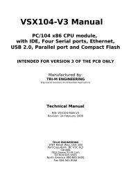
<strong>VDX104</strong> <strong>Manual</strong><br />
CHAPTER 5:<br />
GENERAL PURPOSE INPUT/OUPUT<br />
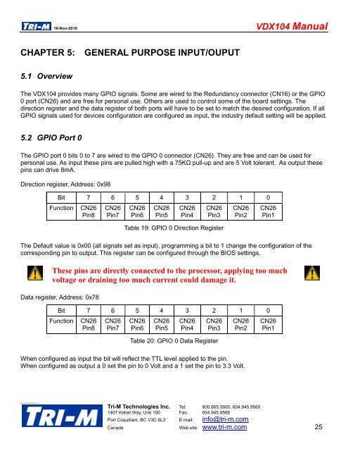
5.1 Overview<br />
The <strong>VDX104</strong> provides many GPIO signals. Some are wired to the Redundancy connector (CN16) or the GPIO<br />
0 port (CN26) and are free for personal use. Others are used to control some of the board settings. The<br />
direction register and the data register of both ports will have to be set to match the desired configuration. If all<br />
GPIO signals used for devices configuration are configured as input, the industry default setting will be applied.<br />
5.2 GPIO Port 0<br />
The GPIO port 0 bits 0 to 7 are wired to the GPIO 0 connector (CN26). They are free and can be used for<br />
personal use. As input these pins are pulled high with a 75KΩ pull-up and are 5 Volt tolerant. As output these<br />
pins can drive 8mA.<br />
Direction register, Address: 0x98<br />
Bit 7 6 5 4 3 2 1 0<br />
Function<br />
CN26<br />
Pin8<br />
CN26<br />
Pin7<br />
CN26<br />
Pin6<br />
CN26<br />
Pin5<br />
CN26<br />
Pin4<br />
CN26<br />
Pin3<br />
Table 19: GPIO 0 Direction Register<br />
CN26<br />
Pin2<br />
CN26<br />
Pin1<br />
The Default value is 0x00 (all signals set as input), programming a bit to 1 change the configuration of the<br />
corresponding pin to output. This register can be configured through the BIOS settings.<br />
These pins are directly connected to the processor, applying too much<br />
voltage or draining too much current could damage it.<br />
Data register, Address: 0x78<br />
Bit 7 6 5 4 3 2 1 0<br />
Function CN26 CN26 CN26 CN26 CN26 CN26 CN26 CN26<br />
Pin8 Pin7 Pin6 Pin5 Pin4 Pin3 Pin2 Pin1<br />
Table 20: GPIO 0 Data Register<br />
When configured as input the bit will reflect the TTL level applied to the pin.<br />
When configured as output a 0 set the pin to 0 Volt and a 1 set the pin to 3.3 Volt.<br />
<strong>Tri</strong>-M Technologies <strong>Inc</strong>. Tel: 800.665.5600, 604.945.9565<br />
1407 Kebet Way, Unit 100 Fax: 604.945.9566<br />
Port Coquitlam, BC V3C 6L3 E-mail: info@tri-m.com<br />
Canada Web site: www.tri-m.com 25