Korg Microkorg Owner's Manual - zZounds.com
Korg Microkorg Owner's Manual - zZounds.com
Korg Microkorg Owner's Manual - zZounds.com

Create successful ePaper yourself
Turn your PDF publications into a flip-book with our unique Google optimized e-Paper software.
E<br />
1
Precautions<br />
Location<br />
Using the unit in the following locations can result in a<br />
malfunction.<br />
• In direct sunlight<br />
• Locations of extreme temperature or humidity<br />
• Excessively dusty or dirty locations<br />
• Locations of excessive vibration<br />
• Close to magnetic fields<br />
Power supply<br />
Please connect the designated AC adapter to an AC outlet of<br />
the correct voltage. Do not connect it to an AC outlet of<br />
voltage other than that for which your unit is intended.<br />
Interference with other electrical devices<br />
Radios and televisions placed nearby may experience<br />
reception interference. Operate this unit at a suitable distance<br />
from radios and televisions.<br />
Handling<br />
To avoid breakage, do not apply excessive force to the<br />
switches or controls.<br />
Care<br />
If the exterior be<strong>com</strong>es dirty, wipe it with a clean, dry cloth.<br />
Do not use liquid cleaners such as benzene or thinner, or<br />
cleaning <strong>com</strong>pounds or flammable polishes.<br />
Keep this manual<br />
After reading this manual, please keep it for later reference.<br />
Keeping foreign matter out of your equipment<br />
Never set any container with liquid in it near this equipment. If<br />
liquid gets into the equipment, it could cause a breakdown,<br />
fire, or electrical shock.<br />
Be careful not to let metal objects get into the equipment. If<br />
something does slip into the equipment, unplug the AC<br />
adapter from the wall outlet. Then contact your nearest <strong>Korg</strong><br />
dealer or the store where the equipment was purchased.<br />
THE FCC REGULATION WARNING (for U.S.A.)<br />
This equipment has been tested and found to <strong>com</strong>ply with the<br />
limits for a Class B digital device, pursuant to Part 15 of the<br />
FCC Rules. These limits are designed to provide reasonable<br />
protection against harmful interference in a residential<br />
installation. This equipment generates, uses, and can radiate<br />
radio frequency energy and, if not installed and used in<br />
accordance with the instructions, may cause harmful<br />
interference to radio <strong>com</strong>munications. However, there is no<br />
guarantee that interference will not occur in a particular<br />
installation. If this equipment does cause harmful interference<br />
to radio or television reception, which can be determined by<br />
turning the equipment off and on, the user is encouraged to<br />
try to correct the interference by one or more of the following<br />
measures:<br />
• Reorient or relocate the receiving antenna.<br />
• Increase the separation between the equipment and receiver.<br />
• Connect the equipment into an outlet on a circuit different<br />
from that to which the receiver is connected.<br />
• Consult the dealer or an experienced radio/TV technician<br />
for help.<br />
Unauthorized changes or modification to this system can void<br />
the user's authority to operate this equipment.<br />
CE mark for European Harmonized Standards<br />
CE mark which is attached to our <strong>com</strong>pany's products of AC<br />
mains operated apparatus until December 31, 1996 means it<br />
conforms to EMC Directive (89/336/EEC) and CE mark<br />
Directive (93/68/EEC).<br />
And, CE mark which is attached after January 1, 1997 means<br />
it conforms to EMC Directive (89/336/EEC), CE mark<br />
Directive (93/68/EEC) and Low Voltage Directive (73/23/<br />
EEC).<br />
Also, CE mark which is attached to our <strong>com</strong>pany's products<br />
of Battery operated apparatus means it conforms to EMC<br />
Directive (89/336/EEC) and CE mark Directive (93/68/EEC).<br />
Data handling<br />
Unexpected malfunctions can result in the loss of memory<br />
contents. Please be sure to save important data on an external<br />
data filer (storage device). <strong>Korg</strong> cannot accept any responsibility<br />
for any loss or damage which you may incur as a result of data<br />
loss.<br />
Printing conventions in this manual<br />
Knobs and keys printed in BOLD TYPE.<br />
Knobs and keys on the panel of the microKORG are printed in<br />
BOLD TYPE.<br />
Parameters " "<br />
Parameters are enclosed in "double quotation marks."<br />
Symbols , ,<br />
These symbols respectively indicate cautions, advice, and MIDIrelated<br />
explanations.<br />
MIDI-related explanations<br />
CC# is used as an abbreviation for Control Change Number.<br />
In MIDI-related explanations, numbers enclosed in square<br />
brackets [ ] are in hexadecimal notation.<br />
Display indications<br />
The numerical values of various parameters appearing in this<br />
manual are only for explanatory purposes. They may not<br />
necessary match what appears in the display of your<br />
microKORG.<br />
Knob positions and parameters<br />
Knob positions and parameter values appearing in this manual<br />
(p.16 and following) are approximations. There may be slight<br />
discrepancies between knob positions and parameter values.<br />
* Company names, product names, and names of formats etc.<br />
are the trademarks or registered trademarks of their respective<br />
owners.<br />
iii
Thank you for purchasing the <strong>Korg</strong><br />
synthesizer/<br />
vocoder. To ensure trouble-free enjoyment, please read this manual<br />
carefully and use the product correctly.<br />
Precautions ................................................................................iii<br />
Data handling ..............................................................................iii<br />
Printing conventions in this manual ...................................................iii<br />
Introduction................................................... 1<br />
Explains the features of the microKORG, and the names and functions of each<br />
part.<br />
Main Features ..............................................................................1<br />
Front and rear panel .......................................................................2<br />
Front panel .......................................................................................................... 2<br />
Rear panel ........................................................................................................... 4<br />
Preparations.................................................. 5<br />
Explains how to connect external audio devices and the included mic, and how to<br />
turn on the power.<br />
Connections .................................................................................5<br />
Connections from the audio outputs................................................................... 5<br />
Connections to the audio inputs ......................................................................... 5<br />
Connections to MIDI equipment/<strong>com</strong>puters ....................................................... 5<br />
Connecting the included mic ............................................................................... 5<br />
Turning the power on ......................................................................6<br />
1. The power supply ............................................................................................ 6<br />
2. Turning the power on ...................................................................................... 6<br />
3. Turning the power off ...................................................................................... 6<br />
Table of Contents<br />
Quick Start .................................................... 7<br />
Explains how to get started using the microKORG (listen to the demos, select<br />
programs, use the arpeggiator and performance functions), and perform basic<br />
editing.<br />
Demo songs .................................................................................7<br />
Listening to the demo songs............................................................................... 7<br />
Synth programs .............................................................................8<br />
1. Selecting and playing a program .................................................................... 8<br />
2. Modifying the sound ....................................................................................... 8<br />
Vocoder programs ....................................................................... 10<br />
1. Playing a vocoder program ........................................................................... 10<br />
2. Modifying the sound ..................................................................................... 10<br />
Arpeggiator ................................................................................ 11<br />
Using the arpeggiator ........................................................................................ 11<br />
Editing ........................................................ 12<br />
Explains what you need to know when editing sounds on the microKORG.<br />
Basic editing .............................................................................. 12<br />
Basic editing procedure .................................................................................... 12<br />
Editing each timbre ........................................................................................... 14<br />
Editing a synth program ................................... 15<br />
Explains the functions of the synth program parameters adjusted by edit control<br />
knobs 1–5 for the corresponding setting of the EDIT SELECT 1/2 knobs.<br />
The structure of a synth program ...................................................... 15<br />
Overview............................................................................................................ 15<br />
iv
Table of Contents<br />
1. VOICE — SYNTH/VOCODER ............................................................................................ 16<br />
2. PITCH — SYNTH/VOCODER ............................................................................................ 17<br />
3. OSC1 (Oscillator 1) — SYNTH/VOCODER .................................................................... 18<br />
4. OSC2 (Oscillator 2) — SYNTH ...................................................................................... 22<br />
5. MIXER — SYNTH ............................................................................................................. 23<br />
6. FILTER — SYNTH ............................................................................................................. 24<br />
7. FILTER EG — SYNTH ...................................................................................................... 26<br />
8. AMP — SYNTH ................................................................................................................. 27<br />
9. AMP EG — SYNTH/VOCODER ......................................................................................... 28<br />
10. LFO 1, 11. LFO 2 — SYNTH/VOCODER ......................................................................... 29<br />
12. PATCH 1, 13. PATCH 2, 14. PATCH 3, 15. PATCH 4 — SYNTH ............................ 30<br />
14. CH PAN A, 15. CH PAN B — VOCODER ...................................................................... 38<br />
Editing the effects and EQ ................................. 39<br />
Explains the function of the effect and EQ parameters adjusted by edit control<br />
knobs 1–5 for the corresponding setting of the EDIT SELECT 1/2 knobs.<br />
The microKORG's effect structure ..................................................... 39<br />
Overview............................................................................................................ 39<br />
16. MOD FX — SYNTH/VOCODER ......................................................................................... 40<br />
17. DELAY — SYNTH/VOCODER ............................................................................................ 41<br />
18. EQ — SYNTH/VOCODER ................................................................................................... 42<br />
Editing a vocoder program ................................ 31<br />
Explains the function of the vocoder program parameters adjusted by edit control<br />
knobs 1–5 for the corresponding setting of the EDIT SELECT 1/2 knobs.<br />
The structure of a vocoder program .................................................. 31<br />
Overview............................................................................................................ 31<br />
1. VOICE — SYNTH/VOCODER ............................................................................................... 32<br />
2. PITCH — SYNTH/VOCODER ............................................................................................... 32<br />
3. OSC1 — SYNTH/VOCODER ................................................................................................ 32<br />
4. AUDIO IN 1 — VOCODER .................................................................................................. 33<br />
5. MIXER — VOCODER ........................................................................................................... 34<br />
6. FILTER — VOCODER .......................................................................................................... 35<br />
7. FC MOD — VOCODER ........................................................................................................ 36<br />
8. AMP — VOCODER ............................................................................................................... 37<br />
9. AMP EG — SYNTH/VOCODER ........................................................................................... 37<br />
10. LFO 1, 11. LFO 2 — SYNTH/VOCODER ......................................................................... 37<br />
12. CH LEVEL A, 13. CH LEVEL B — VOCODER .............................................................. 38<br />
Editing the arpeggiator .................................... 43<br />
Explains the function of the arpeggiator parameters adjusted by edit control knobs<br />
1–5 for the corresponding setting of the EDIT SELECT 1/2 knobs.<br />
The structure of arpeggiator ........................................................... 43<br />
Overview............................................................................................................ 43<br />
19. ARPEG. A — SYNTH/VOCODER ...................................................................................... 44<br />
20. ARPEG. B — SYNTH/VOCODER ...................................................................................... 45<br />
Overall settings (GLOBAL) ................................ 46<br />
Explains the function of the Global parameters adjusted by edit control knobs 1–5<br />
for the corresponding setting of the EDIT SELECT 1/2 knobs.<br />
GLOBAL structure ........................................................................ 46<br />
Overview............................................................................................................ 46<br />
21. GLOBAL .......................................................................................................... 47<br />
v
Table of Contents<br />
Using the microKORG with other MIDI devices (MIDI).. 48<br />
Explains how to make connections with other MIDI devices, and explains the<br />
function of the MIDI parameters adjusted by edit control knobs 1–5 for the<br />
corresponding setting of the EDIT SELECT 1/2 knobs.<br />
MIDI on the microKORG................................................................. 48<br />
Overview............................................................................................................ 48<br />
Connecting MIDI devices/<strong>com</strong>puters ................................................................ 48<br />
MIDI-related settings after connection ............................................................. 49<br />
22. MIDI ................................................................................................................ 51<br />
Messages transmitted and received by the microKORG .......................... 52<br />
Saving Data.................................................. 58<br />
Data dump ............................................................................................................. 62<br />
Restoring the factory settings............................................................................... 63<br />
Write protect setting ............................................................................................. 63<br />
Other SHIFT key functions .................................................................................... 64<br />
Appendix ..................................................... 65<br />
Provides a troubleshooting checklist, and other information such as the specifications<br />
of the microKORG.<br />
LFO 1/2 and delay time synchronization ............................................................... 65<br />
Troubleshooting .................................................................................................... 66<br />
Specifications and options .................................................................................... 67<br />
Index ..................................................................................................................... 68<br />
Explains how to save a program or Global settings that you edited.<br />
Saving your edited settings ............................................................ 58<br />
Saving a program .............................................................................................. 58<br />
Saving GLOBAL, MIDI, and SHIFT function settings ........................................ 58<br />
SHIFT functions ............................................. 59<br />
Explains functions that use the SHIFT key, such as initializing a program and<br />
restoring the factory settings.<br />
Copying and exchanging timbres — SYNTH .................................................................... 59<br />
Initializing a program ............................................................................................ 59<br />
Initializing CH LEVEL and CH PAN — VOCODER ............................................................ 60<br />
MIDI Filter ............................................................................................................. 60<br />
Assigning control changes.................................................................................... 61<br />
vi
Introduction<br />
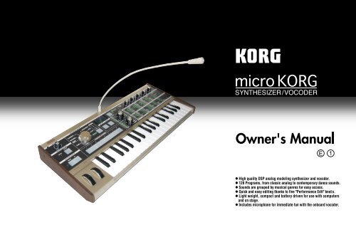
Main Features<br />
1. Analog modeling synthesizer<br />
The analog modeling system of the microKORG uses DSP technology to<br />
simulate an analog synthesizer. Starting with a variety of different oscillator<br />
algorithms (such as the sawtooth and square waves familiar to users of analog<br />
synthesizers) you can use the various controls located on the front panel to edit<br />
any sound, or to create sounds of your own. All sound parameters are organized<br />
into “sections”. By selecting the appropriate section and turning the appropriate<br />
knob you can edit sounds quickly, easily and intuitively. You can also modify the<br />
sound in realtime as you perform.<br />
Number of timbres:<br />
Maximum polyphony:<br />
Structure:<br />
maximum 2 (when layer is used)<br />
4 voices<br />
2 oscillators + noise generator: sawtooth wave, square wave,<br />
triangle wave, sine wave, Vox wave, DWGS x 64, Noise,<br />
Audio In (eight types)<br />
PWM function, OSC Sync function, Ring Mod. function, OSC<br />
Sync+Ring Mod. function<br />
Multimode filters: -24 dB/oct LPF, -12 dB/oct LPF, -12 dB/<br />
oct BPF, -12 dB/oct HPF (four types)<br />
Filter EQ, Amp EG, LFO1, LFO2 (LFO: six waveforms, can be<br />
synchronized to the arpeggiator or to external MIDI clock)<br />
2. Vocoder<br />
You can connect a mic to one of the microKORG's AUDIO IN 1 jacks, and use it as<br />
a vocoder – a device that imposes the spectral character of a voice (or other audio<br />
signal) on the sound of an oscillator, producing the impression that the oscillator is<br />
speaking.<br />
The vocoder consists of eight channels (sixteen filters used in pairs). In addition to<br />
simulating the sounds of classic vocoder units, you can change the filter frequency<br />
and adjust the level and pan of each band to create original vocoder sounds.<br />
Maximum polyphony: 4 voices<br />
Structure:<br />
8 channel vocoder, adjustable level/pan for each channel,<br />
Formant Shift function, 1 oscillator + noise generator (eight types)<br />
Filter EG, Amp EG, LFO1, LFO2 (LFO: six waveforms, can be<br />
synchronized to the arpeggiator or to external MIDI clock)<br />
3. 128 built-in programs<br />
The microKORG contains 128 built-in programs. When shipped, the TRANCE–<br />
S.E./HIT banks contain 112 synth programs, and the VOCODER bank contains<br />
16 vocoder programs.<br />
4. Process the waveform of an external input source<br />
The waveform of an external audio source can be input via the AUDIO IN 1 and<br />
2 jacks, and processed in the same way as the internal waveforms.<br />
5. Virtual Patch function<br />
Modulators and controllers such as filter EG, amp EG, LFO 1/2, keyboard<br />
tracking, and wheel can be virtually patched (without using actual patch cables)<br />
to parameters such as pitch, cutoff, and amp. This gives you even more creative<br />
flexibility.<br />
6. Effects to add the finishing touch to your sound<br />
For even greater possibilities, the microKORG provides three types of modulation<br />
effect, three types of delay, and an equalizer.<br />
The delay effect can be synchronized with the arpeggiator or an external MIDI<br />
clock, allowing numerous applications in live performance.<br />
7. Step Arpeggiator<br />
The microKORG's arpeggiator lets you produce an arpeggio simply by holding<br />
down a chord.<br />
You can choose from six arpeggio types, and adjust the duration and spacing of<br />
the arpeggiated notes. You can also specify whether a note will be on or off for<br />
each of up to eight steps, letting you create a broad range of modified rhythms<br />
and other effects.<br />
1
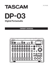
Front and rear panel<br />
Front panel<br />
○ ○ ○ ○ ○ ○ ○ ○ ○ ○ ○ ○ ○ ○ ○ ○ ○ ○ ○ ○ ○ ○ ○ ○ ○ ○ ○ ○ ○ ○ ○ ○ ○ ○ ○ ○ ○ ○<br />
Items on the front panel that relate<br />
to the Vocoder are printed in green.<br />
VOLUME knob<br />
Adjusts the volume of the output<br />
from the OUTPUT jacks (L/MONO,<br />
R) and headphone jack.<br />
ARPEGGIATOR ON/OFF key<br />
Switches the arpeggiator on/off.<br />
(When on, the key LED will light.)<br />
ARPEGGIATOR TEMPO LED<br />
Blinks at the tempo of the<br />
arpeggiator performance. If MIDI<br />
CLOCK is set to External and MIDI<br />
Clock data is being received from<br />
the MIDI IN connector, this LED<br />
will blink at that tempo.<br />
OCTAVE SHIFT UP, DOWN keys<br />
Shifts the pitch range of the<br />
keyboard in steps of an octave, over<br />
a range of +/-3 octaves.<br />
PITCH wheel<br />
Controls the pitch.<br />
MOD wheel<br />
Controls the depth of modulation.<br />
BANK SELECT dial<br />
Selects the program bank.<br />
BANK SIDE key<br />
Switches between the two sides of each program bank.<br />
(The indicator is dark when side A is selected, and lit<br />
when side B is selected.)<br />
This indicator will blink when the microKORG receives<br />
a MIDI program change, or if the BANK SELECT dial<br />
no longer matches the actual bank.<br />
AUDIO IN 1/2 LEDs<br />
These will light if a signal is being input to the<br />
AUDIO IN jacks. They will light red if an<br />
input overload occurs.<br />
Display<br />
Indicates the current program number,<br />
the value of the selected parameter, or<br />
other various messages.<br />
WRITE key<br />
Saves an edited program or global<br />
setting. (➝p.58)<br />
SHIFT key<br />
By holding down this key and pressing<br />
another key, you can access various<br />
utility functions. (➝p.59)<br />
Also, while this key is lit, it will<br />
function as an EXIT key to exit the<br />
current state and return to normal<br />
operation.<br />
PROGRAM NUMBER<br />
1, 2, 3, 4, 5, 6, 7, 8 keys<br />
Select program numbers (the LED of<br />
the selected key will light).<br />
You can also use these keys to turn each<br />
of the eight steps of the arpeggio<br />
on/off, adding variety to an<br />
arpeggiated performance. (➝p.11)<br />
In addition, you can hold down the<br />
SHIFT key and press one of these keys<br />
to access various utility functions.<br />
(SHIFT function)<br />
2
Front and rear panel<br />
TIMBRE SELECT/FORMANT HOLD key<br />
If a Synth program using "layer" is selected,<br />
this key allows you to chose which timbre<br />
will be edited or sounded, or lets you edit<br />
both timbres simultaneously (Sync).<br />
If a Vocoder program is selected, this key<br />
switches Formant Hold on, letting you hold<br />
the tone currently produced by the vocoder<br />
without continuing to speak into the mic.<br />
ORIGINAL VALUE LED<br />
This will light if the value of the parameter<br />
currently being edited matches the value that is<br />
stored in the program. (➝p.13)<br />
(This LED does not function for Performance<br />
Edit.)<br />
EDIT CONTROLS 1, 2, 3, 4, 5 knobs<br />
These knobs edit the Performance Edit<br />
parameters or the parameters of the section<br />
selected by the EDIT SELECT 1 and 2<br />
knobs. (➝p.8, 9, 10)<br />
TIMBRE SELECT 1 LED,<br />
TIMBRE SELECT 2 LED<br />
If a Synth program using Layer is selected,<br />
the LED(s) will light to indicate which<br />
timbre(s) will be edited. If a timbre is being<br />
soloed, its LED will blink.<br />
If a Vocoder program is selected, the 1 LED<br />
will light if the formants are being held.<br />
EDIT SELECT 1 dial,<br />
EDIT SELECT 2 dial<br />
These dials select the section to edit.<br />
(➝p.12)<br />
Vocoder parameters<br />
These are the parameters<br />
for a Vocoder program.<br />
Synth parameters<br />
These are the parameters<br />
for a Synth program.<br />
SYNTH/VOCODER 1 LED,<br />
SYNTH/VOCODER 2 LED<br />
These indicate whether the selected<br />
program is a Synth or a Vocoder program.<br />
If both the SYNTH/VOCODER 1 and 2<br />
LEDs are lit, the Performance Edit function<br />
is enabled.<br />
If only one LED is lit, the EDIT SELECT<br />
knob corresponding to the lit LED will be<br />
the object of your editing. If the object of<br />
editing has not been finalized, the LED will<br />
blink.<br />
3
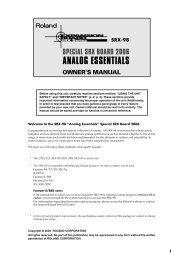
Front and rear panel<br />
○ ○ ○ ○ ○ ○ ○ ○ ○ ○ ○ ○ ○ ○ ○ ○ ○ ○ ○ ○ ○ ○ ○ ○ ○ ○ ○ ○ ○ ○ ○ ○ ○ ○ ○ ○ ○<br />
○<br />
Rear panel<br />
AUDIO IN 2<br />
A Synth program can use an audio signal from an<br />
external device connected here as the oscillator 1<br />
waveform.<br />
A Vocoder program uses this input signal as the<br />
external carrier for the vocoder.<br />
VOLUME 2 knob<br />
Adjusts the input level<br />
from the LINE jack.<br />
LINE jack<br />
Connect a synthesizer<br />
or audio device here.<br />
AUDIO IN 1<br />
A Synth program can use an audio signal from a synthesizer or external device<br />
connected here as the oscillator 1 waveform.<br />
A Vocoder program can use an audio signal from a mic etc. connected here as the<br />
modulator audio.<br />
MIC/LINE switch<br />
If a mic is connected to the DYNAMIC<br />
or CONDENSER jack, set this switch to<br />
the MIC position. If an external<br />
sequencer or audio device is connected,<br />
set this switch to the LINE position.<br />
VOLUME 1 knob<br />
Adjusts the input level from the<br />
DYNAMIC or CONDENSER jack.<br />
CONDENSER jack<br />
Connect a condenser mic to this jack.<br />
DYNAMIC jack<br />
Connect a dynamic mic, synthesizer, or<br />
audio device to this jack.<br />
If both the DYNAMIC jack and the<br />
CONDENSER jack are connected, the<br />
audio signal from the CONDENSER jack<br />
will take priority.<br />
OUTPUT L/MONO, R jacks<br />
Connect these to your powered<br />
monitors, stereo amp, mixer, or<br />
multi-track recorder.<br />
If you want to use the microKORG<br />
in monaural, connect the L/MONO<br />
jack.<br />
HEADPHONES jacks<br />
Connect a pair of<br />
headphones to this jack<br />
(1/4" stereo).<br />
Power switch<br />
Switches the power on/off. (➝p.6)<br />
AC adaptor jack<br />
Connect the included AC adaptor to<br />
this jack. After connecting the AC<br />
adaptor to the microKORG, plug it<br />
into an AC outlet.<br />
MIDI<br />
Use these connectors to connect the microKORG to an external MIDI<br />
device so that MIDI data can be exchanged.<br />
MIDI THRU connector<br />
Received MIDI data is<br />
re-transmitted without<br />
change from this<br />
connector. Use this<br />
when you want to<br />
connect multiple MIDI<br />
devices to the same<br />
"stream" of data.<br />
MIDI OUT connector<br />
This connector<br />
transmits MIDI data.<br />
MIDI IN connector<br />
This connector receives<br />
MIDI data.<br />
Mic holder<br />
You can attach the included<br />
mic to this holder (➝p.5).<br />
4
TAP<br />
EM-1<br />
1 2 3 4 5 7 8 9 10 11 12 13 14 15 16<br />
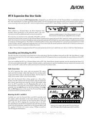
Preparations<br />
The diagram below shows basic connections for the microKORG. Make substitutions<br />
as appropriate for your equipment.<br />
Included mic<br />
Connections<br />
want to use an external sequencer, rhythm machine, or audio source as the carrier<br />
of the vocoder, connect that device to AUDIO IN 2 (➝p.34).<br />
If you want to process the waveform of a synthesizer or sampler, connect a mic or<br />
the output jack of your external device to the AUDIO IN 1 and 2 jacks (➝p.21).<br />
○ ○ ○ ○ ○ ○ ○ ○ ○ ○ ○ ○ ○ ○ ○ ○ ○ ○ ○ ○ ○ ○ ○ ○ ○ ○ ○ ○ ○ ○ ○ ○ ○ ○ ○ ○ ○<br />
○<br />
Connections to MIDI equipment/<strong>com</strong>puters<br />
The keyboard, and controllers etc. of the microKORG can be used to control an<br />
external MIDI tone generator. Conversely, another MIDI keyboard or sequencer can<br />
control the tone generator of the microKORG to produce sound. (➝p.48)<br />
AC adapter (included)<br />
Connect to an AC outlet<br />
MIDI IN<br />
MIDI OUT<br />
MIDI keyboard, tone generator module, rhythm machine etc.<br />
Powered monitors, etc.<br />
Be sure to turn off the power of all devices before making connections. Failing<br />
to take this precaution may cause your speaker system to be damaged, or may<br />
cause malfunctions.<br />
○ ○ ○ ○ ○ ○ ○ ○ ○ ○ ○ ○ ○ ○ ○ ○ ○ ○ ○ ○ ○ ○ ○ ○ ○ ○ ○ ○ ○ ○ ○ ○ ○ ○ ○ ○ ○<br />
○<br />
Connections from the audio outputs<br />
Connect the microKORG's OUTPUT L/MONO and R jacks to the input jacks of<br />
your mixer or powered monitor system.<br />
In order to take full advantage of the potential of the microKORG, we re<strong>com</strong>mend<br />
that you use stereo outputs.<br />
If you are making monaural connections, use the L/MONO jack.<br />
○ ○ ○ ○ ○ ○ ○ ○ ○ ○ ○ ○ ○ ○ ○ ○ ○ ○ ○ ○ ○ ○ ○ ○ ○ ○ ○ ○ ○ ○ ○ ○ ○ ○ ○ ○ ○<br />
○<br />
Connections to the audio inputs<br />
If you want to use the microKORG as a vocoder, connect a mic or other audio<br />
source to AUDIO IN 1, and use that audio source as the modulator (➝p.10). If you<br />
Phones<br />
○ ○ ○ ○ ○ ○ ○ ○ ○ ○ ○ ○ ○ ○ ○ ○ ○ ○ ○ ○ ○ ○ ○ ○ ○ ○ ○ ○ ○ ○ ○ ○ ○ ○ ○ ○ ○<br />
○<br />
Connecting the included mic<br />
A mic for use with the vocoder is included with the microKORG. Here's how to<br />
attach the included mic to the microKORG.<br />
Do not apply excessive force to the neck of the mic, or repeatedly bend it back<br />
and forth any more than necessary. Doing so may cause malfunctions such as<br />
breakage of the internal wiring.<br />
1 Grasp the base of the included mic, align the protrusion of the mic with the slit<br />
of the mic holder, and push it into the holder.<br />
Do not use excessive force.<br />
When removing the included mic, grasp it by the base and pull it out.<br />
2 Turn the rear panel AUDIO IN VOLUME 1 knob<br />
to the MIN position, and set the MIC/LINE switch<br />
Neck<br />
to the MIC position.<br />
3 Connect the plug of the included mic to the<br />
AUDIO IN 1 CONDENSER jack.<br />
Protrusion<br />
Slit<br />
Mic base<br />
5
Turning the power on<br />
○ ○ ○ ○ ○ ○ ○ ○ ○ ○ ○ ○ ○ ○ ○ ○ ○ ○ ○ ○ ○ ○ ○ ○ ○ ○ ○ ○ ○ ○ ○ ○ ○ ○ ○ ○ ○<br />
○<br />
1. The power supply<br />
Before you connect the power supply, make sure that the power switch is turned off<br />
(i.e., in the outward position).<br />
Connecting the AC adaptor<br />
Firmly insert the plug of the included AC adaptor into the jack. Then connect the<br />
AC adaptor to an AC outlet.<br />
Never use any AC adaptor other than the included one.<br />
Inserting/exchanging batteries<br />
The microKORG can also be operated on batteries.<br />
Batteries are not included. You will need to purchase them<br />
separately.<br />
1 Make sure that the power switch on the microKORG is turned off.<br />
Then open the battery cover located on the bottom of the case.<br />
2 Insert six AA alkaline batteries.<br />
Be careful to observe the correct polarity of the batteries.<br />
3 Close the battery cover.<br />
Low battery display “ ”<br />
When the batteries run low, the display will indicate " ," and the "." at the far<br />
right will begin blinking. If you continue using the microKORG, the Protect setting<br />
will be turned on automatically, and you will be unable to edit program or global<br />
settings. We re<strong>com</strong>mend that you install new batteries or switch to the AC adaptor<br />
as soon as possible. If this state occurs while you are editing, and you want to save<br />
your settings, connect the AC adaptor and execute the Write operation.<br />
You can cancel the " " display by pressing the SHIFT key.<br />
Batteries that have be<strong>com</strong>e unusable should be removed from the microKORG<br />
as soon as possible. Leaving such batteries installed may cause malfunctions<br />
(due to battery leakage, etc.). You should also remove the batteries if you will<br />
not be using the microKORG for an extended period of time.<br />
○ ○ ○ ○ ○ ○ ○ ○ ○ ○ ○ ○ ○ ○ ○ ○ ○ ○ ○ ○ ○ ○ ○ ○ ○ ○ ○ ○ ○ ○ ○ ○ ○ ○ ○ ○ ○<br />
○<br />
2. Turning the power on<br />
Before you turn on the microKORG’s power, you should lower the level of your<br />
monitor system or other connected output device.<br />
1 Turn the microKORG's VOLUME knob all the way toward the left.<br />
2 Press the power switch to turn on the power.<br />
The display will indicate the program number.<br />
3 Turn the microKORG's VOLUME knob toward the right to an appropriate<br />
position.<br />
4 Adjust the volume of your external output device.<br />
1, 3<br />
○ ○ ○ ○ ○ ○ ○ ○ ○ ○ ○ ○ ○ ○ ○ ○ ○ ○ ○ ○ ○ ○ ○ ○ ○ ○ ○ ○ ○ ○ ○ ○ ○ ○ ○ ○ ○<br />
○<br />
3. Turning the power off<br />
After saving any necessary data (such as a program you have edited) turn the<br />
power off using the reverse order of the power-on procedure.<br />
Never turn the power off while data is being saved (i.e., while Write is executing).<br />
Doing so may damage the internal data.<br />
2<br />
6
Quick Start<br />
○ ○ ○ ○ ○ ○ ○ ○ ○ ○ ○ ○ ○ ○ ○ ○ ○ ○ ○ ○ ○ ○ ○ ○ ○ ○ ○ ○ ○ ○ ○ ○ ○ ○ ○ ○ ○<br />
○<br />
Listening to the demo songs<br />
The microKORG contains several demo songs.<br />
Here's how to listen to the demo songs and hear the sounds of the microKORG.<br />
1 Hold down the SHIFT key and press the ARPEGGIATOR ON/OFF key.<br />
The demo will begin playing. The SHIFT , OCTAVE SHIFT DOWN, UP , and<br />
PROGRAM NUMBER key LEDs will light.<br />
2 To switch the demo song during playback, press the OCTAVE SHIFT UP or<br />
DOWNkey.<br />
You can also use the PROGRAM NUMBER 1 –8 keys to select a demo song.<br />
3 When you press the SHIFT key, demo playback will stop.<br />
The SHIFT , OCTAVE SHIFT DOWNand UP key will go dark, and the<br />
microKORG will return to normal playing mode.<br />
Demo songs<br />
1<br />
1, 3<br />
2<br />
2<br />
7
Synth programs<br />
○ ○ ○ ○ ○ ○ ○ ○ ○ ○ ○ ○ ○ ○ ○ ○ ○ ○ ○ ○ ○ ○ ○ ○ ○ ○ ○ ○ ○ ○ ○ ○ ○ ○ ○ ○ ○<br />
○<br />
1. Selecting and playing a program<br />
The microKORG contains 128 programs that you can select and play immediately.<br />
Programs are arranged in Banks. Each bank contains two “Sides”, and each side<br />
contains eight programs. To select different programs, use the front panel PRO-<br />
GRAM SELECT knob and PROGRAM NUMBER keys. As an example, here's how<br />
to select program "b.26".<br />
1 Press the BANK SIDE key to select "b" as the program side.<br />
The BANK SIDE key will light when side B is selected, and will be dark when<br />
side A is selected.<br />
2 Turn the PROGRAM SELECT knob to the TECHNO/HOUSE position.<br />
The display will indicate "2" as the program bank.<br />
3 Press the 6 key to select the program number.<br />
Notice that the SYNTH/VOCODER LED for the SYNTH position is lit.<br />
The program will change at the moment you switch either the Side, Bank, or<br />
Number.<br />
4 Play the keyboard to hear the sound.<br />
5 You can use the OCTAVE SHIFT UP or DOWNkeys to shift the pitch range of<br />
the keyboard. (➝p.9)<br />
○ ○ ○ ○ ○ ○ ○ ○ ○ ○ ○ ○ ○ ○ ○ ○ ○ ○ ○ ○ ○ ○ ○ ○ ○ ○ ○ ○ ○ ○ ○ ○ ○ ○ ○ ○ ○<br />
○<br />
2. Modifying the sound<br />
On the microKORG, you can modify the sound to add expression to your performance<br />
by turning the edit control knobs 1 –5 , by moving the PITCH or MOD<br />
wheels, or by the way that you play the keyboard.<br />
Try out various ways to modify the selected program.<br />
Using the Performance Edit function to modify the sound<br />
When both the upper and lower SYNTH/VOCODER LEDs are lit, the Performance<br />
Edit function is active. In this state, the edit control knobs 1 –5 are automatically<br />
assigned to control the parameters listed below. Turn these knobs to control the<br />
sound in realtime.<br />
When using Performance Edit, the display shows the program number.<br />
Performance Edit will be cancelled if you turn the EDIT SELECT 1 or EDIT<br />
SELECT 2 knob to select a different section, or if you hold down the SHIFT key<br />
and press the BANK SIDE key. To enable the Performance Edit function, press<br />
the PROGRAM NUMBER key that is lit.<br />
When Performance Edit is active, you can edit the sound in the following ways.<br />
Knob 1: CUTOFF<br />
Adjusts the cutoff frequency of the filter. This will affect the brightness of the<br />
sound. Normally, turning the knob toward the left will darken the sound, and<br />
turning it toward the right will brighten the sound.<br />
2<br />
1<br />
Program Side SYNTH/VOCODER<br />
Program Bank LED<br />
Program Number<br />
SYNTH/VOCODER LED<br />
TIMBRE SELECT<br />
Edit control knobs 1–5<br />
5<br />
3<br />
EDIT SELECT 2<br />
PROGRAM NUMBER keys 1–8<br />
8
Synth programs<br />
Knob 2: RESONANCE<br />
In the case of a LPF (Low Pass Filter)<br />
Adjusts the resonance of the<br />
filter. This adds a distinctive<br />
character to the sound.<br />
Cutoff Cutoff Cutoff Cutoff<br />
Knob 3: EG ATTACK<br />
(FILTER EG + AMP EG ATTACK)<br />
Low resonance value<br />
High resonance value<br />
Adjusts the attack time of the filter EG and amp EG. This will affect the amount of<br />
time from note-on (when you press a key) until the attack level is reached. Turning<br />
this knob will adjust the speed at which the filter EG and amp EG will rise.<br />
Normally, turning the knob toward the left will shorten the attack time, and turning<br />
it toward the right will lengthen the attack time.<br />
Knob 4: EG RELEASE (FILTER EG + AMP EG RELEASE)<br />
Adjusts the release time of the filter EG and amp EG. This will affect the amount of<br />
time from note-off (when you release<br />
a key) until the sound disappears.<br />
Turning this knob will adjust the<br />
release time of the filter EG and amp<br />
EG. Normally, turning the knob<br />
toward the left will shorten the release<br />
time, and turning it toward the right<br />
will lengthen the release time.<br />
Cutoff<br />
+<br />
Level<br />
Attack Level<br />
0<br />
[3]: Attack Time [4]: Release Time<br />
a: Decay Time b: Sustain Level<br />
Note on<br />
Note off<br />
Knob 5: TEMPO<br />
Adjusts the tempo of the arpeggiator, LFO, and DELAY (if "TEMPO SYNC" is ON).<br />
Turning the knob toward the left will slow down the tempo, and turning it toward<br />
the right will speed up the tempo. The ARPEGGIATOR TEMPO LED will blink at<br />
the specified tempo.<br />
If you have selected a Layer program that uses two timbres (one of the TIMBRE<br />
SELECT LEDs is lit), you can choose which timbre will be affected by your<br />
edits. Press the TIMBRE SELECT key to switch timbres. (➝p.14)<br />
In the EDIT mode, the parameters that are assigned to each knob are also be edited<br />
via the parameters of the section selected by the EDIT SELECT 1 and EDIT<br />
SELECT 2 knobs. For details on each function, refer to p.24 for CUTOFF and<br />
RESONANCE, p.26 and 28 for EG ATTACK and EG RELEASE, or p.44 for TEMPO.<br />
A sound modified modify using Performance Edit can be written into memory<br />
if desired. (➝p.58)<br />
[3]<br />
a<br />
b<br />
[4]<br />
Time<br />
Using the PITCH and MOD wheels for control<br />
PITCH wheel:<br />
The effect will be applied when you move the wheel away from<br />
or toward yourself. When the wheel is in the center position,<br />
there will be no effect.<br />
0<br />
Normally this wheel is used as the pitch bender, so that the<br />
pitch will rise when you move the wheel away, and fall when<br />
0<br />
you move the wheel toward yourself.<br />
MOD wheel:<br />
The effect will be applied when you move the wheel away from yourself, and will<br />
not apply when you move the wheel toward yourself.<br />
You can use this wheel to control the vibrato depth (➝p.17), or to adjust the tone by<br />
controlling the cutoff frequency (➝p.30).<br />
Since the PITCH and MOD wheels can be used as virtual patch sources, you<br />
can use them to produce a variety of effects other than described above. (➝p.30)<br />
Using the OCTAVE SHIFT UP and DOWN keys for control<br />
You can use these keys to shift the<br />
Key operation Keyboard range Key LED<br />
pitches assigned to the keyboard,<br />
C6–C9 UP lit red<br />
Press C5–C8 UP lit orange<br />
in one-octave units over a range of<br />
DOWN key C4–C7 UP lit green<br />
+/-3 octaves. (➝p.8, 52)<br />
Using the keyboard for control<br />
C3–C6<br />
C2–C5<br />
C1–C4<br />
C0–C3<br />
dark<br />
DOWN lit green<br />
DOWN lit orange<br />
DOWN lit red<br />
Key operation<br />
Press UP key<br />
Keyboard Tracking:<br />
Keyboard tracking uses the position of the note on the keyboard to affect the sound.<br />
Normally, this is used to brighten the sound as you play upward, or to create<br />
differences in volume between high and low notes.<br />
Velocity:<br />
The strength with which you play the keyboard can affect the sound.<br />
Normally, your playing strength will affect the tone and volume.<br />
Since velocity and keyboard tracking can be used as a virtual patch source, you<br />
can use them to produce a variety of effects other than those described above.<br />
(➝p.30)<br />
9
10<br />
Vocoder programs<br />
○ ○ ○ ○ ○ ○ ○ ○ ○ ○ ○ ○ ○ ○ ○ ○ ○ ○ ○ ○ ○ ○ ○ ○ ○ ○ ○ ○ ○ ○ ○ ○ ○ ○ ○ ○ ○<br />
○<br />
1. Playing a vocoder program<br />
Here's how to connect the included mic and play a vocoder program.<br />
A vocoder applies the spectral character of an externally-input voice (the "modulator")<br />
to an oscillator or other sound (the "carrier"), and outputs the result. In the<br />
most popular use of a vocoder, you can speak or sing into a mic and play chords on<br />
the keyboard, to create the impression that an instrument is speaking or singing.<br />
Alternatively, you can create a variety of interesting effects by inputting audio<br />
signals other than a human voice (such as<br />
rhythm sounds).<br />
Included mic<br />
1 On the rear panel, turn the AUDIO IN 1<br />
VOLUME 1 knob to the MIN position, and<br />
set the MIC/LINE switch to the MIC<br />
position.<br />
1 1, 4 2<br />
2 Connect the included mic to the AUDIO IN<br />
1 CONDENSER jack.<br />
If you use a mic other than the included<br />
one, connect it to the appropriate jack.<br />
3 Select a vocoder program.<br />
Using the procedure described on page 8,<br />
select program "A.84" for this example.<br />
With the factory settings, the VOCODER bank contains vocoder programs.<br />
Notice that the SYNTH/VOCODER LED VOCODER is lit.<br />
4 Vocalize into the mic, and turn the VOLUME 1 knob toward MAX without<br />
allowing the AUDIO IN 1 LED to light red.<br />
Raising the AMP "DIRECT LEVEL" value will cause the input sound to be<br />
output directly, so raise the level if you want to hear the input sound while you<br />
make adjustments. (➝p.37)<br />
5 While vocalizing into the mic, play the keyboard.<br />
Try pronouncing different words and changing the chords you play, and listen<br />
to the vocoder effect.<br />
If you cannot hear the effect, try adjusting the AMP "LEVEL" (knob 1 ) (➝p.37)<br />
or MIXER "OSC 1 LEVEL" (knob 1 ) (➝p.34).<br />
6 While vocalizing into the mic and using the keyboard to play vocoder sounds,<br />
you can "freeze" the current tone of the vocoder by pressing the FORMANT<br />
HOLD key. This allows you to continue to play the current vocoder sound, even<br />
when you are not vocalizing. This tone will be remembered when you Write the<br />
vocoder program to memory.<br />
Several of the VOCODER bank programs will sound even if you simply play<br />
the keyboard. These programs were written with FORMANT HOLD turned on.<br />
○ ○ ○ ○ ○ ○ ○ ○ ○ ○ ○ ○ ○ ○ ○ ○ ○ ○ ○ ○ ○ ○ ○ ○ ○ ○ ○ ○ ○ ○ ○ ○ ○ ○ ○ ○ ○<br />
○<br />
2. Modifying the sound<br />
In the same way as for a synth program, you can modify the sound of a vocoder<br />
program by turning the edit control knobs 1 –5 , by moving the PITCH and MOD<br />
wheels, and by the way that you play the keyboard. As described on the preceding<br />
pages, try out various changes for the selected program.<br />
The following Performance Edit operations work differently than for a synth<br />
program.<br />
Knob 1: CUTOFF, Knob 2: RESONANCE:<br />
These control the carrier by adjusting the band pass filter cutoff frequency of the<br />
carrier. See page 35.<br />
Knob 3: EG ATTACK, Knob 4: EG RELEASE:<br />
Only the amp EG can be controlled.<br />
Also, a vocoder program does not allow you to switch timbres.<br />
3<br />
4 6 SYNTH/VOCODER Edit control knobs 1–5<br />
LED
Arpeggiator<br />
○ ○ ○ ○ ○ ○ ○ ○ ○ ○ ○ ○ ○ ○ ○ ○ ○ ○ ○ ○ ○ ○ ○ ○ ○ ○ ○ ○ ○ ○ ○ ○ ○ ○ ○ ○ ○<br />
○<br />
Using the arpeggiator<br />
The arpeggiator is a function that automatically arpeggiates the notes of a chord<br />
you play; i.e., sounds the notes one after the other. The microKORG's arpeggiator<br />
provides six types of arpeggio pattern, and lets you adjust the duration (gate time)<br />
of the notes that are sounded. The microKORG also provides a "step arpeggiator"<br />
that lets you specify the on/off status of each note in the chord for as many as eight<br />
steps, letting you create an even wider range of arpeggio patterns.<br />
When you play the chord shown above on the keyboard,<br />
the notes will be sounded as shown at the right. (TYPE: UP)<br />
1 Select a program. (➝p.8)<br />
You can use the arpeggiator with either a synth program or a vocoder program,<br />
but let's select synth program b.58 for this explanation.<br />
2 Press the ARPEGGIATOR ON/OFF key to make the key LED light.<br />
3 Hold down a chord on the keyboard, and the arpeggiator will run.<br />
Modifying the arpeggio<br />
4 Turn the EDIT SELECT 2 knob to the ARPEG.A or ARPEG.B position.<br />
5 Turn the edit control 1 –5 knobs to adjust the arpeggiator parameters, changing<br />
the way that the arpeggiator is sounded.<br />
2, 7<br />
4, 6<br />
5<br />
For example if you selected ARPEG.A in step 4, the parameters shown in the<br />
lower left diagram (below) will be selected as the knob functions. Turning knob<br />
1 will change the tempo of the arpeggio, and turning knob 3 will change the<br />
duration of the arpeggiated notes. Turning knob 4 will switch the arpeggio<br />
pattern, changing the order in which the notes are sounded (➝p.44). (For<br />
details on each parameter, refer to the appropriate page.)<br />
Refer to page 13 for a note regarding cases in which the value does not change.<br />
Using the step arpeggiator to vary the arpeggio<br />
6 If the EDIT SELECT 2 knob is turned to the ARPEG.A or ARPEG.B position,<br />
the PROGRAM NUMBER 1 –5 keys will act as arpeggiator step keys, and will be<br />
lit (the "on" state) for the number of valid steps.<br />
When you press a step key to make the key LED blink (the "off" state), the note<br />
of the corresponding step will change to a rest, and the resulting arpeggio will<br />
change (see the diagram below). The Step Arpeggiator function lets you switch<br />
each step of the arpeggio on/off in this way to modify the arpeggio that is<br />
sounded.<br />
To change the number of valid steps in the arpeggio, set the EDIT SELECT 2<br />
knob to ARPEG.B and turn knob 4 . (➝p.45)<br />
7 When you press the ARPEGGIATOR ON/OFF key (the key LED goes dark), the<br />
arpeggio will stop playing.<br />
TYPE: UP<br />
LAST STEP: 8<br />
6<br />
11
Editing<br />
○ ○ ○ ○ ○ ○ ○ ○ ○ ○ ○ ○ ○ ○ ○ ○ ○ ○ ○ ○ ○ ○ ○ ○ ○ ○ ○ ○ ○ ○ ○ ○ ○ ○ ○ ○ ○<br />
○<br />
Basic editing procedure<br />
All of the editable parameters are organized into "sections". Each section contains<br />
up to five parameters, which are controlled using the edit control knobs 1 – 5. The<br />
two knobs labelled EDIT SELECT 1 and EDIT SELECT 2 are used to select a<br />
section. Notice the six columns of text under the five knobs. The first column<br />
identifies the name of each section, and the following five columns show the<br />
parameter assigned to each of the knobs above. The text to the left side indicates the<br />
parameters used for a synth program. The text to the right side (in green) indicates<br />
the parameters available for a vocoder program.<br />
On the microKORG there are two basic ways for you to create a sound.<br />
• Select the program that is closest to the sound you want to create, and edit that<br />
program as necessary to change it as desired<br />
• Start from an initialized program ("blank slate"), and create the sound from<br />
scratch<br />
Broadly speaking, the procedure is as follows.<br />
1 Select the program that you want to start from. (➝p.8)<br />
If you want to start from scratch, execute the Initialize operation. (➝p.59)<br />
2 Turn the EDIT SELECT 1 or EDIT SELECT 2 knob to select the section that<br />
includes the parameter you want to edit. (The SYNTH/VOCODER LED for the<br />
side you are editing will light.)<br />
Consider how the current program differs from the sound you have in mind,<br />
and select the parameter that you want to edit.<br />
If you are creating the sound from scratch, note that the<br />
EDIT SELECT 1 and EDIT SELECT 2 knobs access<br />
parameter sections in a logical order for creating the<br />
sound. You can turn the dials in sequence to step through<br />
these parameter sections in the appropriate order.<br />
By holding down the SHIFT key and pressing the BANK<br />
SIDE key, you can switch between EDIT SELECT 1 and<br />
EDIT SELECT 2 as the section to edit.<br />
4<br />
Basic editing<br />
3 Turn edit control knob 1, 2, 3, 4, or 5 to edit the assigned parameters.<br />
For example if you are editing a synth program and set the EDIT SELECT 1<br />
knob to FILTER, the parameters shown below the diagram at the bottom of this<br />
page will be selected as the function of the five edit control knobs. (The left<br />
parameter of each pair is the synth program parameter, and the right parameter<br />
– in green – is the vocoder program parameter.)<br />
Turning knob 2 will change the cutoff frequency value, affecting the tone.<br />
Turning knob 3 will change the resonance value, adding a distinctive character<br />
to the tone. (➝p.24)<br />
Go ahead and try editing the AMP EG parameters "ATTACK" and "DECAY"<br />
(➝p.28), the PITCH parameter "PORTAMENTO" (➝p.17), or the MOD FX<br />
(➝p.40) or DELAY (➝p.41) parameters to hear the result. (For details on each<br />
parameter, refer to the appropriate page.)<br />
4 If you want to make precise adjustments to a value, hold down the SHIFT key<br />
and press the OCTAVE SHIFT UP or DOWN key (UP, DOWN, and SHIFT keys<br />
will light). Now you can use the UP and DOWN octave keys to step through<br />
the values for the selected parameter.<br />
To cancel this function, press the lit SHIFT key.<br />
If you press the UP and DOWN keys simultaneously, that parameter will return<br />
to the value it had when you selected it.<br />
5 Repeat steps 2–4 as necessary to create the desired sound.<br />
6 Write the program into memory. (➝p.58)<br />
BANK SIDE<br />
4 ORIGINAL VALUE<br />
SYNTH/VOCODER LED<br />
2 3<br />
12
-12dB/oct<br />
-24dB/oct<br />
Basic editing<br />
If you select another program or turn the power off before you write, your edits<br />
will be lost.<br />
If the parameter value does not change when you turn knobs 1–5<br />
When you use EDIT SELECT 1 or EDIT SELECT 2 to select a section and turn<br />
knobs 1–5 to edit the parameter values, the value in the display will sometimes<br />
continue blinking, and the parameter value will not change.<br />
This occurs when there is a discrepancy between the actual value of the<br />
parameter being edited (the value that is blinking in the display) and the<br />
position of the knob. If the actual value is significantly different from the<br />
position of the knob, and the value changed immediately when you moved the<br />
knob, the sound would change in a sudden and unnatural way.<br />
To prevent this from happening, the knob and parameter will begin changing in<br />
tandem only when the knob position corresponds to the actual value of the<br />
edited parameter (the value in the display will stop blinking).<br />
For example, suppose that you turn knob 1 to edit a parameter,<br />
so that the knob is in the position shown at left.<br />
Then you use the EDIT SELECT 1 knob to switch to a different<br />
parameter section, and want to edit the parameter assigned to<br />
knob 1. The actual value of this parameter is at the position of<br />
the triangle in the diagram at left. (The actual value will blink<br />
when you turn the knob slightly.) The parameter value will not<br />
change until you turn the knob all the way to that position.<br />
When the knob reaches the position of the actual value, the knob<br />
and parameter value will begin changing in tandem, so that you<br />
can edit the value. (When the knob reaches the actual value, the<br />
value in the display will stop blinking.)<br />
To return to the original parameter values of a program<br />
The edit control ORIGINAL VALUE LED will light to indicate the parameter<br />
values of a preset program or a program that you saved.<br />
If you want to return parameters to their original values, turn knobs 1–5 so that<br />
the ORIGINAL VALUE LED is lit.<br />
If you select another program or re-select the same program while you are<br />
editing, all parameters will return to the values of the preset program or the<br />
previously-saved program.<br />
In the same way as when editing a program, you can make settings for the<br />
entire microKORG or MIDI-related settings by selecting the desired parameter<br />
section and turning knobs 1–5 to make the settings (➝p.47, 51). Changes you<br />
make to these settings will also be lost if you turn the power off, so you must<br />
Write them if you want to keep your changes.<br />
How to read the pages for each section (➝p.16–)<br />
This indicates the position of<br />
the EDIT SELECT 1/2 knob.<br />
The EDIT SELECT 1/2 knob<br />
selects the section that will be<br />
edited. In this example, the<br />
FILTER section is selected.<br />
These are the edit control knobs<br />
1—5. The markings printed<br />
around each knob are the<br />
values that will be selected<br />
when you turn that knob. These<br />
positions are approximate.<br />
This area lists the parameters<br />
that are edited by edit control<br />
knobs 1—5 when the above<br />
section is selected. The range of<br />
values for each parameter is<br />
given in square brackets [ ].<br />
Explanations of each parameter<br />
and its values are given below.<br />
This is the name of the section.<br />
When you have set the EDIT<br />
SELECT 1 or 2 knob to the<br />
FILTER position and would like<br />
to see an explanation of the<br />
parameters, refer to this page.<br />
24<br />
6. FILTER — SYNTH<br />
This section applies to<br />
synth programs.<br />
A summary of this section<br />
is given here.<br />
The filter removes unwanted frequency regions of the sound produced by the oscillator. It determines the tone by allowing only the desired<br />
portion of the sound to pass. "TYPE" (knob 1) selects the type of filter (i.e., the way in which it will cut the frequency). "CUTOFF" (knob 2) sets<br />
the frequency at which the cut will occur. Normally, turning this knob toward the right will brighten the sound, and turning it toward the left<br />
will darken the sound. "RESONANCE" (knob 3) emphasizes the frequency region near the cutoff frequency, adding a distinctive character to<br />
the sound. Other parameters in this section let you specify the depth of the modulation applied by the filter EG, and the way in which keyboard<br />
tracking will affect the cutoff frequency.<br />
TYPE [-24dB LPF, -12dB LPF, CUTOFF [0...127] RESONANCE [0...127] FILTER EG INT [-63...63] FILTER KEY TRACK [-63...63]<br />
-12dB BPF, -12dB HPF] Sets the cutoff frequency.<br />
Sets the resonance of the filter. This specifies how time-variant This specifies how keyboard tracking<br />
(the keyboard location that you<br />
Increasing this value will raise the This will emphasize the overtones modulation from the Filter EG will<br />
Selects the type of filter<br />
cutoff frequency.<br />
near the cutoff frequency specified be applied to the cutoff frequency play) will affect the cutoff frequency.<br />
24dB LPF ( ):<br />
by "Cutoff," adding a distinctive (➝Figure 6-5). The cutoff frequency<br />
"CUTOFF" can be varied by<br />
The -24 dB LPF (-24 dB/octave Low<br />
character to the sound. Increasing will change over time according to For example if the sound played by<br />
time-variant change produced<br />
Pass Filter) is the most <strong>com</strong>mon<br />
this value will Figure increase 6-4 the effect. the Filter EG settings, modifying the C4 key has the desired tone but<br />
by Filter EG, by keyboard playing<br />
dynamics (velocity), and by<br />
type of filter; it passes the frequencies<br />
that are below the cutoff fre-<br />
(➝Figure 6-4)<br />
the tone. For example, you can use higher notes no longer have resonance<br />
or are too mellow-sounding,<br />
note location (keyboard tracking).<br />
knob will affect the overtones that<br />
Since movement of the "CUTOFF"<br />
this to create a sound that gradually<br />
begins to brighten when you you can adjust keyboard tracking to<br />
quency, and cuts the frequencies<br />
that are above (➝Figure 6-1). Lowering<br />
the cutoff frequency will If the "CUTOFF" value is low-<br />
are boosted by resonance, it is best<br />
press the key, and then gradually make <strong>com</strong>pensations so that the<br />
to adjust "CUTOFF" and "RESObe<strong>com</strong>es<br />
darker.<br />
cutoff frequency will rise for higher<br />
make the tone darker and more ered, the volume may be extremely<br />
low, or you may hear no<br />
NANCE" in conjunction with each<br />
This INT (Intensity) parameter notes.<br />
mellow.<br />
other.<br />
specifies the depth (sensitivity) to<br />
With positive (+) settings, the cutoff<br />
frequency will rise as you play<br />
sound at all.<br />
-12dB LPF ( ):<br />
which the Filter EG will affect the<br />
The -12 dB LPF (-12 dB/octave Low<br />
cutoff frequency.<br />
upward from the C4 note, and fall<br />
Pass Filter) has a more gentle slope<br />
With a setting of 0, the Filter EG will<br />
The effect of resonance<br />
as you play downward. With negative<br />
(-) settings, the cutoff frequency<br />
than the -24 dB LPF, producing a<br />
not affect the cutoff frequency. Increasingly<br />
positive (+) settings will<br />
more natural-sounding effect.<br />
will fall as you play upward from<br />
LPF<br />
(➝"-24 dB LPF")(➝Figure 6-1)<br />
allow the Filter EG to have a correspondingly<br />
greater effect on the<br />
the C4 note, and rise as you play<br />
Figure 6-1<br />
downward.<br />
cutoff frequency. (➝Figure 6-6)<br />
LPF (Low Pass Filter)<br />
Increasingly negative (-) settings With a setting of +48, the change<br />
HPF<br />
will allow a correspondingly in cutoff frequency will be proportionate<br />
to the change in<br />
greater effect in the opposite direction.<br />
(➝Figure 6-7)<br />
pitch. With a setting of 0, keyboard<br />
tracking will not affect the<br />
BPF<br />
Frequency<br />
cutoff frequency.<br />
Cutoff<br />
Low resonance value<br />
High resonance value<br />
13
Basic editing<br />
○ ○ ○ ○ ○ ○ ○ ○ ○ ○ ○ ○ ○ ○ ○ ○ ○ ○ ○ ○ ○ ○ ○ ○ ○ ○ ○ ○ ○ ○ ○ ○ ○ ○ ○ ○ ○<br />
○<br />
Editing each timbre<br />
Synth programs can have up to two timbres.<br />
A timbre consists of the parameters of EDIT SELECT 1 VOICE (except for<br />
"SYNTH/VOCODER" and "SINGLE/LAYER") through LFO2 sections, and the<br />
parameters of EDIT SELECT 2 PATCH 1–4 sections.<br />
The VOICE section parameters "SYNTH/VOCODER" and "SINGLE/LAYER"<br />
apply to the entire program.<br />
Using both timbres (Layer)<br />
❍ Set the EDIT SELECT 1 knob to VOICE, and turn knob 2 to select<br />
LAYER ( ).<br />
Selecting the timbre to edit<br />
If you are editing a program that uses both timbres, here's how to select the timbre<br />
to edit.<br />
❍ Press the EDIT SELECT TIMBRE SELECT key to select the timbre that you<br />
want to edit. (The corresponding TIMBRE SELECT LED will light.)<br />
Your editing will affect the selected timbre.<br />
You can also edit both timbres simultaneously (Edit Sync).<br />
1 Press and hold the TIMBRE SELECT key for at least two seconds.<br />
Both TIMBRE SELECT LEDs will light, and editing will be synchronized for the<br />
two timbres. The display will indicate the value for timbre 1. The value of<br />
timbre 1 will also be used as the value at which editing begins.<br />
2 To cancel edit sync, press the TIMBRE SELECT key.<br />
Edit sync will be cancelled, and timbre 1 will be the object of<br />
editing.<br />
You can use the Solo function even while editing is<br />
synchronized.<br />
The state of the edit sync function is not saved.<br />
Listening to only one timbre (Solo)<br />
For a program that uses both timbres, you can use the Solo function to hear just one<br />
timbre. This is convenient when you want to hear just one timbre while you edit.<br />
1 Hold down the SHIFT key and press the TIMBRE SELECT key.<br />
The TIMBRE SELECT LED for the timbre selected for editing will start blinking,<br />
and only that timbre will sound.<br />
2 If you want to hear only the other timbre, once again hold down the SHIFT key<br />
and press the TIMBRE SELECT key.<br />
The TIMBRE SELECT LED for the other timbre will start blinking, and only that<br />
timbre will sound. The timbre selected for editing will also change at this time.<br />
3 To cancel the Solo function, press the TIMBRE SELECT key.<br />
The Solo state cannot be memorized.<br />
Exchanging and copying the settings of the timbres<br />
(SHIFT function)<br />
You can exchange the settings of the two timbres, or copy the timbre settings from<br />
another program. (➝p.59)<br />
SHIFT<br />
TIMBRE SELECT<br />
14
Editing a synth program<br />
○ ○ ○ ○ ○ ○ ○ ○ ○ ○ ○ ○ ○ ○ ○ ○ ○ ○ ○ ○ ○ ○ ○ ○ ○ ○ ○ ○ ○ ○ ○ ○ ○ ○ ○ ○ ○<br />
○<br />
Overview<br />
The three attributes of sound: pitch, tone, and volume<br />
Sound has three basic attributes; pitch, tone, and volume.<br />
To control these attributes, the microKORG analog modeling synthesizer provides<br />
"oscillator," "filter," and "amp (amplifier)" sections, just as on the analog synthesizers<br />
of the past.<br />
The "oscillator" settings vary the pitch, the "filter" settings modify the tone, and the<br />
"amp" settings modify the volume.<br />
The microKORG's "oscillator," "filter," and "amp"<br />
On the microKORG, the OSC1, OSC2, and PITCH sections control the "oscillator".<br />
The PITCH section specifies the pitch of the waveform that is the basis of the<br />
sound, and the OSC1 and OSC2 sections select the waveforms. The waveforms<br />
generated here are mixed by the MIXER section.<br />
The microKORG's FILTER section modifies the tone. Then the AMP section<br />
modifies the volume and outputs the final sound.<br />
These three sections determine the basic sound of the program.<br />
EG, LFO, keyboard tracking, virtual patch, controllers<br />
In addition to the sections described above, the microKORG provides ways in<br />
which the sound can be varied according to time, key range, or various types of<br />
performance expression. These are controlled by modulators and controllers such<br />
as EG (envelope generator), LFO (Low Frequency Oscillator), keyboard tracking,<br />
Virtual Patch, and the PITCH and MOD wheels. You can use these modulators and<br />
controllers to apply change to the basic sound of the program.<br />
Figure 0-1 (at right) shows the structure of a synthesizer sound on the microKORG.<br />
Look at TIMBRE 1, and notice how the signal flows in the order of OSC ➝ FILTER<br />
➝ AMP. Also notice how modulators such as EG and LFO can affect these blocks.<br />
The structure of a synth program<br />
As shown in figure 0-1, a synth program consists of timbres 1/2, effects, and the<br />
arpeggiator.<br />
TIMBRE 1/2<br />
Each timbre consists of OSC, FILTER, AMP, EG, LFO, and Virtual Patch blocks. You<br />
can create more <strong>com</strong>plex programs by using two timbres together in one program<br />
using the Layer feature.<br />
EFFECTS<br />
The output of timbres 1/2 is sent to the modulation effect (MOD FX) ➝ delay effect<br />
(DELAY) ➝ equalizer (EQ).<br />
For the modulation effect you can choose from three types of effect such as chorus.<br />
For the delay, you can choose from three types of delay such as stereo delay. The EQ<br />
is a two-band equalizer.<br />
ARPEGGIATOR<br />
You can apply the arpeggiator to a timbre. If the program uses two timbres, you can<br />
apply the arpeggiator to either or both timbres. This is a step arpeggiator with six<br />
arpeggio types.<br />
Figure 0-1<br />
(in the case of Layer)<br />
Free Assign<br />
KBD Track<br />
Velocity<br />
Mod. wheel<br />
Pitch bend<br />
15
1. VOICE — SYNTH/VOCODER<br />
These settings determine the basic character of the program, and how it will sound.<br />
"SYNTH/VOCODER" (knob 1) specifies whether the program will be a synth program or a vocoder program. If you want this to be a synth<br />
program, select Synthesizer ( ). "SINGLE/LAYER" (knob 2) specifies whether both timbres will be used (Layer) in the case of a synth<br />
program. Other parameters in this section specify whether the program will sound monophonically/polyphonically/unison, and how the<br />
notes will be triggered.<br />
If you simultaneously press more keys than the specified number of voices, the last-pressed key will take priority.<br />
SYNTH/VOCODER<br />
[Synthesizer, Vocoder]<br />
Switches the currently selected program<br />
between a Synthesizer program<br />
and a Vocoder program.<br />
Synthesizer ( ):<br />
The program will be a synth program.<br />
You can use two oscillators<br />
to create the sound.<br />
Vocoder ( ):<br />
The program will be a vocoder program.<br />
You can use sound input<br />
from a connected mic to produce<br />
"talking" instrument effects.<br />
The parameters for editing will<br />
vary depending on whether<br />
Synthesizer or Vocoder is selected<br />
here.<br />
SINGLE/LAYER [Single, Layer]<br />
Specifies how many timbres the<br />
program will use. This cannot be<br />
selected for a vocoder program.<br />
Single ( ):<br />
Only one timbre will be used.<br />
Figure 1-1<br />
Timbre1<br />
Layer ( ):<br />
Two timbres will be used. When<br />
you play the keyboard, both timbres<br />
will sound simultaneously.<br />
You can edit each timbre individually.<br />
Figure 1-2<br />
Timbre2<br />
Timbre1<br />
The maximum polyphony is four<br />
voices (four notes). In the case of<br />
a Layer program, these four<br />
voices are divided between timbres<br />
1 and 2, so only two keys can<br />
be played in a layered program.<br />
VOICE ASSIGN<br />
[Mono, Poly, Unison]<br />
Specifies how the timbre will be<br />
sounded.<br />
Mono ( ):<br />
The timbre will sound monophonically.<br />
The program will play only<br />
one note at a time.<br />
Poly ( ):<br />
The program will sound polyphonically,<br />
allowing you to play chords.<br />
The maximum polyphony is four<br />
voices.<br />
Unison ( ):<br />
All four voices will sound in unison<br />
at the same pitch. Use "UNI-<br />
SON DETUNE" to specify the pitch<br />
difference in steps of one cent.<br />
"VOICE ASSIGN" and polyphony for<br />
a Layer program<br />
Timbre 1 Timbre 2<br />
VOICE ASSIGN Mono Poly<br />
Polyphony 1 voice 3 voices<br />
VOICE ASSIGN Poly Poly<br />
Polyphony 2 voices 2 voices<br />
VOICE ASSIGN Unison Mono<br />
Polyphony 2 voices 1 voices<br />
TRIGGER MODE [Single, Multi]<br />
Specifies whether the EG and LFO<br />
will be retriggered when you play<br />
the next key while still holding<br />
down the previous key.<br />
You can edit this if "VOICE AS-<br />
SIGN" is Mono or Unison.<br />
Single ( ):<br />
The EG and LFO will not be<br />
retriggered by the second or subsequent<br />
key. Use this setting if you<br />
want to play legato.<br />
Multi ( ):<br />
The EG and LFO will be retriggered<br />
each time you press a key.<br />
Figure 1-3<br />
Single<br />
Multi<br />
EG<br />
Trigger<br />
EG<br />
Trigger<br />
Note on<br />
Note on<br />
UNISON DETUNE [0...99]<br />
Specifies the amount of detuning<br />
(in steps of one cent) between the<br />
notes sounded by Unison mode.<br />
You can edit this if "VOICE AS-<br />
SIGN" is set to Unison.<br />
The detuning method will depend<br />
on the number of unison voices.<br />
Figure 1-4<br />
2 voice<br />
4 voice<br />
99<br />
0<br />
99<br />
0<br />
Unison<br />
Detune<br />
Unison<br />
Detune<br />
16
2. PITCH — SYNTH/VOCODER<br />
These settings specify the pitch of the oscillator.<br />
Use "TRANSPOSE" (knob 1) and "TUNE" (knob 2) to set the desired pitch. These settings are shared by oscillators 1 and 2. In this section you<br />
can also set the portamento time, and specify how the PITCH and MOD wheels will affect the pitch.<br />
TRANSPOSE [-24...24]<br />
Adjusts the pitch of the oscillator in<br />
semitone (100 cent) steps.<br />
The range is two octaves upward or<br />
downward.<br />
Changes made by the front<br />
panel OCTAVE SHIFT buttons<br />
actually shift the pitches assigned<br />
to the keyboard (or keys)<br />
in one-octave steps, and do not<br />
affect the pitch of the oscillator<br />
that is sounding. Nor are such<br />
settings saved by the Write operation.<br />
If you wish to change<br />
the pitch of the oscillator itself,<br />
you must use this "TRANS-<br />
POSE" setting to specify the<br />
pitch.<br />
TUNE [-50...50]<br />
Adjusts the pitch of the oscillator in<br />
one-cent steps.<br />
PORTAMENTO [0...127]<br />
Specifies the speed of the<br />
portamento effect (a smooth change<br />
in pitch from one note to the next<br />
note of a different pitch).<br />
With a setting of 0, there will be no<br />
portamento effect. Increasing this<br />
value will cause the pitch change to<br />
occur over a longer time.<br />
If "VOICE ASSIGN" is set to<br />
Mono or Unison, and if "Trigger"<br />
is set to Single, portamento will<br />
not apply to the first-sounded<br />
note.<br />
BEND RANGE [-12...12]<br />
Specifies the amount of pitch<br />
change in semitones that will occur<br />
when the pitch wheel is operated.<br />
This value specifies the amount of<br />
change that will occur when you<br />
move the pitch wheel all the way<br />
to the away from you.<br />
VIBRATO INT [-63...63]<br />
Specifies the depth of vibrato that<br />
will be applied when you move the<br />
MOD (modulation) wheel all the<br />
way away from yourself.<br />
The LFO2 modulates the pitch of<br />
the oscillator, raising and lowering<br />
it to create vibrato.<br />
17
3. OSC1 (Oscillator 1) — SYNTH/VOCODER<br />
The oscillator generates the waveform that is the basis of the sound.<br />
The timbre has two oscillators. The settings in this section are for oscillator 1. "WAVE" (knob 1) selects the basic waveform for oscillator 1,<br />
and "CONTROL 1" (knob 2) and "CONTROL 2" (knob 3) modify the waveform. For example if you set "WAVE" to Saw ( ), adjusting the<br />
"CONTROL 1" value will modify the sound, changing the waveform as shown in figure 3-1. Adjusting "CONTROL 2" will apply LFO1<br />
modulation to the waveform specified by "CONTROL 1," producing additional change.<br />
WAVE<br />
[Saw, Square, Triangle, Sine, Vox,<br />
DWGS, Noise, Audio In]<br />
Selects the waveform for oscillator 1.<br />
Saw Wave ( ):<br />
This is a sawtooth wave. This waveform<br />
is shaped like the tooth of a<br />
saw, and contains a rich overtone<br />
spectrum.<br />
You can use this to create numerous<br />
instrumental sounds such as<br />
string and brass sounds, or typical<br />
analog synth sounds such as synth<br />
bass or synth brass.<br />
CONTROL 1 [0...127/– – –]<br />
Adjusts a parameter specific to the<br />
selected waveform.<br />
CONTROL 1 has no effect if<br />
"WAVE" is set to DWGS.<br />
CONTROL 1 [0...127]:<br />
Adjusting this value will modify the<br />
waveform.<br />
A setting of 0 will produce a conventional<br />
sawtooth wave, and a setting<br />
of 127 will produce a sawtooth<br />
wave one octave higher.<br />
(➝Figure 3-1)<br />
CONTROL 2 [0...127/1...64]<br />
Adjusts a parameter specific to the<br />
selected waveform.<br />
CONTROL 2 [0...127]:<br />
LFO1 is used to apply modulation<br />
to the waveform specified by<br />
"CONTROL 1." The "CONTROL 2"<br />
setting specifies the depth of the<br />
modulation produced by LFO1.<br />
For example by setting LFO1<br />
"WAVE" to Triangle ( ) and adjusting<br />
the LFO speed, you can produce<br />
a detune-like effect.<br />
Figure 3-1<br />
0 63 127<br />
18<br />
Square Wave ( ):<br />
This is a square wave. It has a rectangular<br />
shape, and strictly speaking is<br />
actually square only when the top and<br />
bottom of the waveform have the same<br />
width (a "pulse width" of 50%). If the<br />
pulse width is other than 50%, this is<br />
also called a pulse wave.<br />
A square wave is used for woodwind<br />
sounds such as clarinet, and for<br />
wooden percussion sounds. A pulse<br />
wave is used for plucked-string<br />
sounds and reed-type sounds.<br />
CONTROL 1 [0...127]:<br />
Adjusts the pulse width. A setting<br />
of 0 produces a pulse width of 50%<br />
(square wave), and a setting of 127<br />
produces a pulse width of 0% (there<br />
will be no sound). The sound will<br />
be<strong>com</strong>e "harder" as you adjust this<br />
parameter toward 0%.<br />
(➝Figure 3-2)<br />
CONTROL 2 [0...127]:<br />
LFO1 is used to apply PWM (pulse<br />
width modulation)* 3-1 to the pulse<br />
width specified by "CONTROL 1."<br />
The "CONTROL 2" setting specifies<br />
the depth of the modulation produced<br />
by LFO1. For example by<br />
setting LFO1 "WAVE" to Triangle<br />
( ) and adjusting the LFO<br />
speed, you can add depth to the<br />
sound.<br />
Figure 3-2<br />
0 63 127<br />
*3-1: PWM<br />
Pulse Width Modulation refers to the<br />
use of a separate signal to vary the<br />
pulse width over time. On the<br />
microKORG, you can use PWM to<br />
modify the tone via LFO1, or via Virtual<br />
Patch from modulation sources<br />
LFO2, Filter EG, or Amp EG.
3. OSC1 (Oscillator 1) — SYNTH/VOCODER<br />
WAVE<br />
CONTROL 1 CONTROL 2<br />
Triangle Wave ( ):<br />
This is a triangle wave, which has<br />
weaker overtones and a stronger<br />
fundamental than a sawtooth wave<br />
or square wave. It is suitable for<br />
mellow bass sounds.<br />
CONTROL 1 [0...127]:<br />
You can modify the waveform by<br />
adjusting this value.<br />
A setting of 0 will produce a triangle<br />
wave, and a setting of 127 will produce<br />
a waveform with a pitch that<br />
is one octave and a fifth higher.<br />
(➝Figure 3-3)<br />
CONTROL 2 [0...127]:<br />
LFO1 is used to apply wave form<br />
modulation to the waveform specified<br />
by "CONTROL 1." The "CON-<br />
TROL 2" setting specifies the depth<br />
of the modulation produced by<br />
LFO1.<br />
Figure 3-3<br />
0 63 127<br />
Sine Wave ( ):<br />
This is a sine wave. This waveform<br />
contains only the fundamental, and<br />
no overtones at all. It can be used<br />
to create claves or bass drum<br />
sounds. In some synth programs,<br />
oscillator 2 is used to perform cross<br />
modulation* 3-2 (➝Figure 3-4), creating<br />
a more <strong>com</strong>plex overtone structure.<br />
Cross modulation by a sine wave<br />
cannot be applied to a vocoder program.<br />
Since a sine wave contains no<br />
overtones, the filter will not<br />
modify its tone.<br />
Vox Wave ( ):<br />
This simulates a waveform similar<br />
to human vocal cords. Even if the<br />
oscillator pitch is changed, the frequency<br />
spectrum will be maintained,<br />
which makes this effective<br />
when used for vocal-type sounds or<br />
as a vocoder oscillator.<br />
Select HPF or BPF as the filter, and<br />
adjust "Cutoff" to create a vocaltype<br />
sound.<br />
CONTROL 1 [0...127]:<br />
On a synth program, this adjusts the<br />
depth of cross modulation.<br />
On a vocoder program, this modifies<br />
the waveform.<br />
CONTROL 1 [0...127]:<br />
Adjusting this value will modify the<br />
waveform. (➝Figure 3-5)<br />
CONTROL 2 [0...127]:<br />
On a synth program, this adjusts the<br />
depth of additional modulation<br />
applied by LFO1 to the cross modulation<br />
specified by "CONTROL 1."<br />
On a vocoder program, this adjusts<br />
the depth of modulation applied by<br />
LFO1 to the waveform that you selected<br />
by "CONTROL 1."<br />
CONTROL 2 [0...127]:<br />
LFO1 is used to apply modulation<br />
to the waveform specified by<br />
"CONTROL 1." CONTROL 2 sets<br />
the depth of the modulation applied<br />
by LFO1.<br />
Figure 3-4<br />
X-mod Depth + X-mod Depth Mod<br />
OSC2<br />
OSC1<br />
OSC1 Output<br />
Figure 3-5<br />
0 63 127<br />
*3-2: Cross Modulation<br />
This is a type of oscillator modulation<br />
available on analog synthesizers<br />
of the past. Normally, a low-frequency<br />
signal (such as from an LFO)<br />
is used as the modulation source for<br />
an oscillator, but Cross Modulation<br />
lets you use another oscillator as the<br />
modulation source, creating sounds<br />
with a <strong>com</strong>plex overtone structure<br />
that would not normally be produced<br />
otherwise. On the microKORG, you<br />
can use oscillator 2 to apply cross<br />
modulation if a sine wave is selected<br />
for oscillator 1. Gradually raise the<br />
"CONTROL 1" level, and notice how<br />
the sound changes. This can produce<br />
distorted sounds, or sounds with a<br />
metallic character.<br />
You can produce an even wider variety<br />
of effects by adjusting the OSC2<br />
"SEMITONE" or "TUNE" parameters.<br />
You can also achieve interesting results<br />
by applying sync modulation<br />
and cross modulation at the same<br />
time.<br />
19
3. OSC1 (Oscillator 1) — SYNTH/VOCODER<br />
WAVE CONTROL 1 CONTROL 2<br />
DWGS ( )<br />
(Digital Waveform Generator System):<br />
This is waveform data created by<br />
harmonic additive synthesis.<br />
Choose this when you want to create<br />
sounds with a distinctive "digital-synth"<br />
character, such as synth<br />
bass, electric piano, bell, or horn. 64<br />
types of waveform are provided.<br />
Noise ( ):<br />
This generates white noise. Within<br />
the oscillator, a LPF (Low Pass Filter)<br />
is provided to process the noise.<br />
(➝Figure 3-6). You can use this to<br />
create percussion sounds, or sound<br />
effects such as surf. This can also be<br />
used in conjunction with another<br />
timbre to simulate the "breath" <strong>com</strong>ponent<br />
of a wind instrument sound.<br />
CONTROL 1 [– – –]:<br />
– – –<br />
CONTROL 1 [0...127]:<br />
This sets the cutoff frequency of the<br />
LPF.<br />
Adjusting this will affect the noise<br />
waveform.<br />
Figure 3-6<br />
Noise<br />
Genarator<br />
Resonance<br />
LPF<br />
Cutoff<br />
CONTROL 2 [1...64]:<br />
Selects the DWGS waveform.<br />
(➝Table 3-1)<br />
DWGS waveform data was first<br />
used in the <strong>Korg</strong> DW-6000<br />
(which went on sale in 1984),<br />
and has continued to be developed<br />
since that time.<br />
CONTROL 2 [0...127]:<br />
This controls the resonance of the<br />
LPF.<br />
If you raise this enough to produce<br />
an identifiable pitch, the cutoff frequency<br />
will move according to the<br />
keyboard location you play, and the<br />
change will be heard as a pitch.<br />
If you want the oscillation produced<br />
by resonance to match the<br />
reference pitch, set "CONTROL<br />
1" to 24.<br />
Table 3-1<br />
DWGS List<br />
No. Name No. Name No. Name<br />
1 SynSine1 24 5thWave1 47 Clav1<br />
2 SynSine2 25 5thWave2 48 Clav2<br />
3 SynSine3 26 5thWave3 49 Guitar1<br />
4 SynSine4 27 Digi1 50 Guitar2<br />
5 SynSine5 28 Digi2 51 Guitar3<br />
6 SynSine6 29 Digi3 52 Bass1<br />
7 SynSine7 30 Digi4 53 Bass2<br />
8 SynBass1 31 Digi5 54 Bass3<br />
9 SynBass2 32 Digi6 55 Bass4<br />
10 SynBass3 33 Digi7 56 Bass5<br />
11 SynBass4 34 Digi8 57 Bell1<br />
12 SynBass5 35 Endless* 58 Bell2<br />
13 SynBass6 36 E.Piano1 59 Bell3<br />
14 SynBass7 37 E.Piano2 60 Bell4<br />
15 SynWave1 38 E.Piano3 61 Voice1<br />
16 SynWave2 39 E.Piano4 62 Voice2<br />
17 SynWave3 40 Organ1 63 Voice3<br />
18 SynWave4 41 Organ2 64 Voice4<br />
19 SynWave5 42 Organ3<br />
20 SynWave6 43 Organ4<br />
21 SynWave7 44 Organ5<br />
22 SynWave8 45 Organ6<br />
23 SynWave9 46 Organ7<br />
*: The 35 Endless waveform simulates an endless<br />
scale, in which notes one octave apart have the identical<br />
pitch. You can play an ascending or descending<br />
scale as far as you wish, producing the sensation<br />
that a scale of the same pitch is continuing infinitely.<br />
20
TAP<br />
EM-1<br />
1 2 3 4 5 7 8 9 10 11 12 13 14 15 16<br />
3. OSC1 (Oscillator 1) — SYNTH/VOCODER<br />
WAVE CONTROL 1 CONTROL 2<br />
Audio In ( ):<br />
The waveform of the audio signal<br />
input from the AUDIO IN 1 or 2<br />
jacks will be used instead of an oscillator.<br />
This lets you apply filtering to a<br />
drum phrase, or synthesize a vocal<br />
or guitar sound together with oscillator<br />
2.<br />
The parameters of the PITCH<br />
section have no effect on the<br />
waveform that is input from the<br />
AUDIO IN 1 or 2 jacks.<br />
CONTROL 1 [0...127]:<br />
This adjusts the volume balance<br />
between AUDIO IN 1 and AUDIO<br />
IN 2. With a setting of 127 only AU-<br />
DIO IN 1 will be output. With a setting<br />
of 0, only AUDIO IN 2 will be<br />
output.<br />
CONTROL 2 [0...127]:<br />
LFO1 is used to apply modulation<br />
to the volume balance between<br />
AUDIO IN 1 and AUDIO IN 2 that<br />
you set by "CONTROL 1." The<br />
"CONTROL 2" setting sets the<br />
depth of this modulation produced<br />
by LFO1.<br />
This lets you create effects in which<br />
the AUDIO IN 1 and 2 inputs are<br />
alternated.<br />
Processing an external input audio signal<br />
You can use the filter, amp, EG, and LFO etc. to process the signal from a external<br />
synthesizer, rhythm machine, or audio device in the same way as an oscillator waveform.<br />
Before you connect an external device, turn off the power of the microKORG and of<br />
any external output devices and power amps.<br />
1 Turn the rear panel AUDIO IN 2 VOLUME 2 knob to the MIN position.<br />
2 Connect the output jack of your external device to the AUDIO IN 2 LINE jack.<br />
3 After making connections, turn the power on in the order of your external device, the<br />
microKORG, and finally your powered monitor speaker system.<br />
4 Select a program to initialize, and initialize it.<br />
For this example, select any synth program, and initialize the program as described<br />
on page 59.<br />
5 Turn the EDIT SELECT 1 knob to the OSC 1 position, and turn knob 1 ("WAVE") to<br />
select " " (Audio In).<br />
6 Input an audio signal from your external device, and turn the VOLUME 2 knob<br />
toward MAX as far as possible without allowing the AUDIO IN 2 LED to light red.<br />
7 While inputting an audio signal, play the keyboard.<br />
8 As described in "Basic editing procedure" (➝p.12), edit the FILTER, AMP, EG, LFO,<br />
and effects to modify the sound.<br />
The PITCH-related parameters have no effect on the sound from the AUDIO IN jacks.<br />
MIDI IN<br />
In this example, you could connect the microKORG's MIDI OUT to the MIDI IN of<br />
your external MIDI device and set the MIDI channels to match, so that your sound<br />
module or other external MIDI device will produce sound when you play the<br />
keyboard of the microKORG (➝p.49). You can use the microKORG's keyboard to play<br />
the sounds of your external device, and use the EDIT SELECT 1/2 knobs and the edit<br />
control knobs 1–5 to modify the sound.<br />
You can use an external input as the carrier of the vocoder. (➝p.34)<br />
MIDI OUT<br />
LINE OUT<br />
tone generator module, rhythm machine,<br />
or audio device<br />
21
4. OSC2 (Oscillator 2) — SYNTH<br />
Here you can make settings for oscillator 2.<br />
You can create a variety of sounds by using two oscillators together. For example you can adjust "SEMITONE" (knob 3) and "TUNE (knob 4)<br />
so that one oscillator acts as though it were part of the overtone structure of the other oscillator, set the pitches of the two oscillators to an<br />
interval of harmony, or set both oscillators to the same pitch but slightly detune one of them to create a detuning effect.<br />
You can also use Ring Modulation and Oscillator Sync to create very <strong>com</strong>plex overtone structures. (This is set by "OSC MOD" (knob 2).)<br />
22<br />
WAVE [Saw, Square, Triangle]<br />
Selects the waveform for oscillator<br />
2.<br />
Saw Wave ( ):<br />
A sawtooth wave. (➝p.18)<br />
Square Wave ( ):<br />
A square wave. (➝p.18)<br />
Triangle Wave ( ):<br />
A triangle wave. (➝p.19)<br />
If you do not hear the sound of<br />
oscillator 2, raise the MIXER<br />
"OSC2 LEVEL" (knob 2). If you<br />
want to hear only the sound of<br />
oscillator 2, lower the MIXER<br />
"OSC 1 LEVEL" (knob 1).<br />
OSC MOD<br />
[OFF, Ring, Sync, RingSync]<br />
Selects the type of oscillator modulation<br />
that will be produced in conjunction<br />
with oscillator 1.<br />
OFF ( ):<br />
The sound will be output without<br />
applying oscillator modulation.<br />
You can adjust "SEMITONE" and<br />
"TUNE" to produce harmony,<br />
detune, or harmonic-<strong>com</strong>ponent<br />
effects.<br />
Ring ( ):<br />
Ring modulation * 4-1 will be applied.<br />
(➝Figure 4-1)<br />
By adjusting "SEMITONE" and<br />
"TUNE" you can create metallic<br />
sounds with little sense of pitch.<br />
This is effective for sound effects.<br />
Sync ( ):<br />
Oscillator sync * 4-2 will be applied.<br />
This is useful for creating synthlead<br />
sounds. (➝Figure 4-2)<br />
RingSync ( ):<br />
This simultaneously applies Ring<br />
and Sync modulation. (➝Figure 4-3)<br />
SEMITONE [-24...24]<br />
Specifies the detuning (pitch difference)<br />
relative to oscillator 1, in<br />
semitone steps over a range of 2<br />
octaves upward or downward.<br />
If you want to use the sound of<br />
oscillator 2 as a <strong>com</strong>ponent in<br />
the oscillator 1 overtone structure,<br />
try setting it one octave or<br />
a fifth higher than oscillator 1. If<br />
you want to use oscillator 2 in<br />
harmony, you can try intervals<br />
such as a third, fourth, or fifth.<br />
Figure 4-1<br />
OSC2 Wave<br />
OSC1 Wave<br />
Figure 4-2<br />
OSC2 Wave<br />
Sync<br />
OSC1 Wave<br />
Figure 4-3<br />
OSC2 Wave<br />
Sync<br />
OSC1 Wave<br />
OSC2 Output<br />
OSC1 Output<br />
OSC2 Output<br />
OSC1 Output<br />
OSC2 Output<br />
OSC1 Output<br />
TUNE [-63...63]<br />
Specifies the amount of detune for<br />
OSC2 relative to OSC1.<br />
A setting of ±63 produces a pitch<br />
difference of ±2 octaves, and ±48<br />
produces a pitch difference of ±1<br />
octave. A value near 0 will make<br />
fine adjustments in the pitch.<br />
If "OSC MOD" is set to Sync,<br />
adjustments in "Semitone" or<br />
"Tune" will change the pitch of<br />
the overtones. The pitch of the<br />
fundamental will not change.<br />
*4-1: Ring Modulation:<br />
This modulation generates a sum and<br />
difference of the oscillator 1 and 2<br />
waveforms.<br />
For example you can select a square<br />
wave for the oscillator, set "TRANS-<br />
POSE" to 0, "SEMITONE" to 24, and<br />
adjust "TUNE" to produce a clear<br />
bell-like sound. The effect will be<br />
easier to detect if you lower "OSC 1<br />
LEVEL" and raise "OSC 2 LEVEL."<br />
You can also create interesting effects<br />
by using Virtual Patch to modulate<br />
OSC 2 TUNE from LFO or EG.<br />
*4-2: Oscillator Sync:<br />
This modulation forcibly synchronizes<br />
the phase of oscillator 2 to the<br />
phase of oscillator 1.<br />
For example, select sawtooth wave<br />
for oscillator 1 and raise the "OSC 2<br />
LEVEL." Then, edit "SEMITONE" and<br />
"TUNE" to change the pitch, and notice<br />
the result. The effect will be more<br />
noticeable if the oscillator 2 pitch is<br />
raised above the oscillator 1 pitch.<br />
You can also produce interesting effects<br />
by using Virtual Patch to modulate<br />
OSC 2 Tune from LFO or EG.
5. MIXER — SYNTH<br />
These parameters adjust the volume balance of the oscillator 1 and 2, and the noise generator.<br />
"OSC 1 LEVEL" (knob 1) sets the output level of oscillator 1, "OSC 2 LEVEL" (knob 2) sets the output level of oscillator 2, and "NOISE<br />
LEVEL" (knob 3) sets the output level of the noise generator.<br />
These settings will be the input level to the filter.<br />
OSC 1 LEVEL [0...127]<br />
Sets the output level of oscillator 1.<br />
OSC 2 LEVEL [0...127]<br />
Sets the output level of oscillator 2.<br />
NOISE LEVEL [0...127]<br />
Sets the output level of the noise<br />
generator.<br />
This noise generator generates<br />
white noise. This is independent of<br />
the white noise that can be selected<br />
as a waveform for oscillator 1. This<br />
does not have filter or resonance (as<br />
the oscillator 1 noise generator, but<br />
you can use the FILTER section to<br />
create the same results as the noise<br />
waveform of oscillator 1.<br />
Noise is used to create percussion<br />
instrument sounds, or sound effects<br />
such as surf.<br />
23
6. FILTER — SYNTH<br />
The filter controls the tonal character of the sound produced by the oscillator. It determines the tone by allowing only the desired portion of<br />
the sound to pass. "TYPE" (knob 1) selects the type of filter (i.e., the way in which it will cut the frequency). "CUTOFF" (knob 2) sets the<br />
frequency at which the cut will occur. Normally, turning this knob toward the right will brighten the sound, and turning it toward the left<br />
will darken the sound. "RESONANCE" (knob 3) emphasizes the frequency region near the cutoff frequency, adding a distinctive character to<br />
the sound. Other parameters in this section let you specify the depth of the modulation applied by the filter EG, and the way in which<br />
keyboard tracking will affect the cutoff frequency.<br />
24<br />
TYPE<br />
[-24dB LPF, -12dB LPF,<br />
-12dB BPF, -12dB HPF]<br />
Selects the type of filter<br />
-24dB LPF ( ):<br />
The -24 dB LPF (-24 dB/octave Low<br />
Pass Filter) is the most <strong>com</strong>mon<br />
type of filter; it passes the frequencies<br />
that are below the cutoff frequency,<br />
and cuts the frequencies<br />
that are above (➝Figure 6-1). Lowering<br />
the cutoff frequency will<br />
make the tone darker and more<br />
mellow.<br />
-12dB LPF ( ):<br />
The -12 dB LPF (-12 dB/octave Low<br />
Pass Filter) has a more gentle slope<br />
than the -24 dB LPF, producing a<br />
more natural-sounding effect.<br />
(➝"-24 dB LPF")(➝Figure 6-1)<br />
Figure 6-1<br />
LPF (Low Pass Filter)<br />
Cutoff<br />
-12dB/oct<br />
-24dB/oct<br />
Frequency<br />
CUTOFF [0...127]<br />
Sets the cutoff frequency.<br />
Increasing this value will raise the<br />
cutoff frequency.<br />
"CUTOFF" can be varied by<br />
time-variant change produced<br />
by Filter EG, by keyboard playing<br />
dynamics (velocity), and by<br />
note location (keyboard tracking).<br />
If the "CUTOFF" value is set too<br />
low, the volume may be extremely<br />
low, or you may hear no<br />
sound at all.<br />
Figure 6-4<br />
The effect of resonance<br />
LPF<br />
HPF<br />
BPF<br />
Low resonance value<br />
RESONANCE [0...127]<br />
Sets the resonance of the filter.<br />
This will emphasize the overtones<br />
near the cutoff frequency specified<br />
by "CUTOFF," adding a distinctive<br />
character to the sound. Increasing<br />
this value will increase the effect.<br />
(➝Figure 6-4)<br />
Since movement of the "CUTOFF"<br />
knob will affect the overtones that<br />
are boosted by resonance, it is best<br />
to adjust "CUTOFF" and "RESO-<br />
NANCE" in conjunction with each<br />
other.<br />
High resonance value<br />
FILTER EG INT [-63...63]<br />
This specifies how time-variant<br />
modulation from the Filter EG will<br />
be applied to the cutoff frequency<br />
(➝Figure 6-5). The cutoff frequency<br />
will change over time according to<br />
the Filter EG settings, modifying<br />
the tone. For example, you can use<br />
this to create a sound that gradually<br />
begins to brighten when you<br />
press the key, and then gradually<br />
be<strong>com</strong>es darker.<br />
This INT (Intensity) parameter<br />
specifies the depth (sensitivity) to<br />
which the Filter EG will affect the<br />
cutoff frequency.<br />
With a setting of 0, the Filter EG will<br />
not affect the cutoff frequency. Increasingly<br />
positive (+) settings will<br />
allow the Filter EG to have a correspondingly<br />
greater effect on the<br />
cutoff frequency. (➝Figure 6-6)<br />
Increasingly negative (-) settings<br />
will allow a correspondingly<br />
greater effect in the opposite direction.<br />
(➝Figure 6-7)<br />
FILTER KEY TRACK [-63...63]<br />
This specifies how keyboard tracking<br />
(the keyboard location that you<br />
play) will affect the cutoff frequency.<br />
For example if the sound played by<br />
the C4 key has the desired tone but<br />
higher notes no longer have resonance<br />
or are too mellow-sounding,<br />
you can adjust keyboard tracking to<br />
make <strong>com</strong>pensations so that the<br />
cutoff frequency will rise for higher<br />
notes.<br />
With positive (+) settings, the cutoff<br />
frequency will rise as you play<br />
upward from the C4 note, and fall<br />
as you play downward. With negative<br />
(-) settings, the cutoff frequency<br />
will fall as you play upward from<br />
the C4 note, and rise as you play<br />
downward.<br />
With a setting of +48, the change<br />
in cutoff frequency will be proportionate<br />
to the change in<br />
pitch. With a setting of 0, keyboard<br />
tracking will not affect the<br />
cutoff frequency.
6. FILTER — SYNTH<br />
TYPE<br />
-12dB BPF ( ):<br />
-12dB/oct BPF (Band Pass Filter)<br />
allows a frequency band in the region<br />
of the cutoff frequency to pass,<br />
and cuts the remaining frequencies.<br />
It is used when you wish to emphasize<br />
only a specific portion of the<br />
frequency range.(➝Figure 6-2)<br />
Use this when you want to emphasize<br />
just a specific region of the<br />
sound. For example, you can use<br />
this to create a bandwidth-limited<br />
sound similar to sound heard from<br />
a small radio or a telephone.<br />
Figure 6-2<br />
BPF (Band Pass Filter)<br />
Cutoff<br />
Frequency<br />
FILTER KEY TRACK<br />
Keyboard Track operates according<br />
to the pitch that is controlled<br />
by pitch bend, and transpose.<br />
It is not affected by pitch<br />
changes produced by vibrato or<br />
Virtual Patch.<br />
-12dB HPF ( ):<br />
-12dB/oct HPF (High Pass Filter)<br />
allows frequencies above the cutoff<br />
frequency to pass, and cuts the<br />
lower frequencies. Use this when<br />
you wish to make the sound thinner.<br />
However if the cutoff frequency<br />
is raised excessively, the volume<br />
will decrease significantly. (➝Figure<br />
6-3)<br />
For example you can use the HPF<br />
to purposely attenuate the low-frequency<br />
region of a sound that will<br />
be played together with other lowfrequency<br />
instruments, in order to<br />
differentiate that sound from the<br />
other instruments.<br />
Figure 6-3<br />
HPF (High Pass Filter)<br />
Cutoff<br />
Frequency<br />
Filter oscillation<br />
If you raise the resonance to a high value, it will oscillate (produce a<br />
sound) at the frequency specified by the cutoff frequency. You can use<br />
filter oscillation ("self-oscillation") as a sound source. If the filter is<br />
oscillating, the "CUTOFF" parameter that normally adjusts the tone will<br />
instead control the pitch of the oscillation. This can be used in a variety of<br />
ways. Whistling is a typical example, and can be produced by adjusting<br />
the ADSR parameters of the filter EG. You can also try setting "FILTER EG<br />
INT" to a negative value. Another possibility is to select the MOD wheel<br />
or LFO 1/2 as a source in Virtual Patch, and use it to control "CUTOFF" as<br />
a destination.<br />
Figure 6-5<br />
Figure 6-6<br />
Cutoff<br />
Cutoff<br />
Cutoff frequency<br />
specified by<br />
“Cutoff”<br />
Figure 6-7<br />
Cutoff frequency<br />
specified by<br />
“Cutoff”<br />
Cutoff<br />
Note on<br />
Attack<br />
Time<br />
Sustain Level<br />
Decay<br />
Time<br />
Int=+32<br />
Note on<br />
Note off<br />
Note on<br />
Int=–32<br />
Note off<br />
Note off<br />
Release Time<br />
Int=+63<br />
Note on Note off<br />
Note on<br />
Int=–63<br />
Note off<br />
Time<br />
Int=0<br />
Time<br />
Int=0<br />
Time<br />
25
7. FILTER EG — SYNTH<br />
Here you can make settings for the filter EG, which applies time-variant change to the tone (➝Figure 7-1). Make these settings to specify the<br />
"shape" of the EG, and use the FILTER parameter "FILTER EG INT" to specify the amount of effect that the EG will have (➝p.24). By making<br />
FILTER EG settings, you can make the tone change as time passes. Create the desired tonal curve by adjusting the ADSR parameters;<br />
ATTACK (knob 1), DECAY (knob 2), SUSTAIN (knob 3), RELEASE (knob 4).<br />
For details on how an EG (Envelope Generator) works, refer to AMP EG (➝p.28).<br />
You can use the FILTER EG as a Virtual Patch source modulate a parameter other than the filter cutoff frequency. (➝p.30)<br />
ATTACK [0...127]<br />
Specifies the time from note-on<br />
(when the key is pressed) until the<br />
attack level (maximum value of the<br />
envelope) is reached.<br />
Figure 7-1<br />
Cutoff<br />
Attack Level<br />
0<br />
Note on<br />
[1]<br />
[2]<br />
[3]<br />
Note off<br />
DECAY [0...127]<br />
Specifies the time from when the attack<br />
level is reached until the sustain<br />
level (SUSTAIN) is reached.<br />
[4]<br />
[1]: Attack Time [3]: Sustain Level<br />
[2]: Decay Time [4]: Release Time<br />
Time<br />
SUSTAIN [0...127]<br />
Specifies the cutoff frequency that<br />
will be maintained after the decay<br />
time has elapsed, until you release<br />
the key.<br />
RELEASE [0...127]<br />
Specifies the time from note-off<br />
(when the key is released) until the<br />
level reaches 0.<br />
Filter EG and Amplifier EG<br />
When the Filter EG changes the cutoff frequency, the tone will change.<br />
However depending on the volume changes produced by the Amplifier<br />
EG, this can be heard in different ways. For example by changing the<br />
speed at which the tone and volume begin (attack) or decay, you can<br />
significantly vary the character of the tonal change. It is a good idea to<br />
adjust the changes of both the Filter EG (tone) and the Amplifier EG<br />
(volume) as you proceed with editing.<br />
EG RESET<br />
[OFF, ON]<br />
Specifies whether or not the EG will<br />
be reset for the second and subsequent<br />
note-on. If a new note is<br />
played before the previous note has<br />
finished its release stage, the envelope<br />
can either start over from zero,<br />
or continue from the current value.<br />
OFF ( ):<br />
The note will start from the current<br />
EG level.<br />
ON ( ):<br />
The second note-on will start from<br />
a level of 0.<br />
OFF<br />
ON<br />
Note on<br />
Note off<br />
Note on (Retrigger)<br />
The "EG RESET" parameter is<br />
only available if "VOICE AS-<br />
SIGN" is set to Poly, or if "VOICE<br />
ASSIGN" is set to Mono or Unison<br />
and "TRIGGER" is set to<br />
Multi.<br />
26
8. AMP (Amplifier) — SYNTH<br />
These parameters specify the volume. The sound that is created by passing through the oscillator and filter is amplified by the amp. "LEVEL"<br />
(knob 1) adjusts the volume. "KBD TRACK" (knob 4) adjusts how keyboard tracking will affect the volume, and "DISTORTION" (knob 3)<br />
specifies whether the sound will be distorted.<br />
You can use "PANPOT" (knob 2) to set the pan (stereo position of the sound).<br />
LEVEL [0...127]<br />
Adjusts the volume of the timbre.<br />
If the "SINGLE/LAYER" is Layer,<br />
this setting will adjust the volume<br />
balance between timbre 1 and timbre<br />
2.<br />
PANPOT [L63...Center...R63]<br />
Adjusts the location of the sound in<br />
the stereo field.<br />
L63( ) is far left, Center ( )<br />
is center, and R63 ( ) is far right.<br />
DISTORTION [OFF, ON]<br />
Specifies whether distortion will be<br />
applied to the output of the timbre.<br />
The degree of distortion is adjusted<br />
by the output level of each oscillator<br />
in the MIXER.<br />
OFF ( ):<br />
Distortion is off.<br />
ON ( ):<br />
Distortion is on.<br />
KBD TRACK [-63...63]<br />
Specifies how keyboard tracking<br />
will affect the volume.<br />
With positive (+) settings, the volume<br />
will increase as you play above<br />
the C4 note on the keyboard, and<br />
will decrease as you play below C4.<br />
With negative (-) settings, the volume<br />
will decrease as you play<br />
above the C4 note on the keyboard,<br />
and will increase as you play below<br />
C4.<br />
Keyboard Track operates according<br />
to the pitch that is controlled<br />
by pitch bend, and transpose.<br />
It is not affected by pitch<br />
changes produced by vibrato or<br />
Virtual Patch.<br />
27
9. AMP EG — SYNTH/VOCODER<br />
Here you can make settings for the AMP EG, which applies time-variant change to the volume (➝Figure 9-1). By making AMP EG settings,<br />
you can make the volume change as time passes. Create the desired volume curve by adjusting the ADSR parameters; ATTACK (knob 1),<br />
DECAY (knob 2), SUSTAIN (knob 3), RELEASE (knob 4).<br />
You can use AMP EG as a Virtual Patch source to modulate parameters other than volume. (➝p.30)<br />
ATTACK [0...127]<br />
Specifies the time from note-on<br />
(when the key is pressed) until the<br />
attack level (maximum value of the<br />
envelope) is reached.<br />
DECAY [0...127]<br />
Specifies the time from when the attack<br />
level is reached until the sustain<br />
level (SUSTAIN) is reached.<br />
EG (Envelope Generator)<br />
To a significant extent, each sound has its own distinctive volume curve.<br />
For example when you play a note on a piano, the note begins at the<br />
maximum volume, and gradually diminishes. When you release your<br />
finger from the key, the sound will disappear quickly with a brief decay.<br />
Volume curves such as this are an important aspect of how we identify the<br />
sound of a specific instrument. This type of change also occurs in the tone<br />
and pitch, as well as in the volume. On a synthesizer, this type of change is<br />
produced by an EG. The microKORG has dedicated EGs for the filter and<br />
for the amp. However since these EGs can be used as Virtual Patch<br />
sources, you are also free to use them to vary the pitch or numerous other<br />
aspects of the sound.<br />
Some example settings are shown below.<br />
SUSTAIN [0...127]<br />
Specifies the volume that will be<br />
maintained after the decay time has<br />
elapsed, as long as you continue<br />
holding the key.<br />
Figure 9-1<br />
Level<br />
Attack Level<br />
0<br />
Note on<br />
[1]<br />
[2]<br />
[3]<br />
Note off<br />
RELEASE [0...127]<br />
Specifies the time from note-off<br />
(when the key is released) until the<br />
level reaches 0.<br />
[4]<br />
[1]: Attack Time [3]: Sustain Level<br />
[2]: Decay Time [4]: Release Time<br />
Time<br />
EG RESET<br />
[OFF, ON]<br />
Specifies whether or not the EG will<br />
be reset for the second and subsequent<br />
note-on. If a new note is<br />
played before the previous note has<br />
finished its release stage, the envelope<br />
can either start over from zero,<br />
or continue from the current value.<br />
OFF ( ):<br />
The note will start from the current<br />
EG level.<br />
ON ( ):<br />
The second note-on will start from<br />
a level of 0.<br />
OFF<br />
ON<br />
Note on<br />
Note off<br />
Note on (Retrigger)<br />
Piano<br />
Level<br />
Note on<br />
Note off<br />
0 Time<br />
Organ<br />
Level<br />
Note on<br />
Note off<br />
0 Time<br />
Strings<br />
Level<br />
Note on<br />
Note off<br />
0 Time<br />
The "EG RESET" parameter is<br />
available only when "VOICE<br />
ASSIGN" is Poly, or when<br />
"VOICE ASSIGN" is Mono or<br />
Unison and "TRIGGER" is Multi.<br />
Attack: 0 Sustain: 0<br />
Decay: 100 – 127 Release: 5–25<br />
Attack: 0 Sustain: 127<br />
Decay: — Release: 0<br />
Attack: 40 Sustain: 75<br />
Decay: 50 Release: 50<br />
28
10. LFO 1, 11. LFO 2 — SYNTH/VOCODER<br />
The timbre has two LFOs (Low Frequency Oscillator).<br />
The cyclic change produced by an LFO can modulate various aspects of the sound such as the pitch, tone, or volume.<br />
Use "WAVE" (knob 1) to select the LFO waveform, knob 2 to select the key sync method, "TEMPO SYNC" (knob 3) to synchronize the LFO<br />
cycle to the tempo, and "FREQUENCY"/"SYNC NOTE" (knob 4) to specify the frequency.<br />
LFO1 and LFO2 can be used as Virtual Patch sources to apply modulation to a variety of parameters. (➝p.30)<br />
WAVE (LFO1) [Saw, Square1,<br />
Triangle, Sample&Hold]<br />
WAVE (LFO2) [Saw, Square2,<br />
Sine, Sample&Hold]<br />
Selects the LFO waveform.<br />
Figure 10-1<br />
Saw ( ):<br />
Square1 ( ):<br />
Square2 ( ):<br />
Triangle ( ):<br />
Sine ( ):<br />
Sample&Hold ( ):<br />
Amplitude changes<br />
irregularly<br />
(sample & hold)<br />
KEY SYNC [OFF, Timbre, Voice] TEMPO SYNC<br />
Specifies how the LFO will be applied<br />
to a voice when note-on occurs.<br />
OFF ( ):<br />
The LFO phase will not be reset<br />
when note-on occurs.<br />
(➝Figure 10-2)<br />
Timbre ( ):<br />
The LFO phase will be reset at the<br />
first note-on that occurs from a state<br />
of no keys pressed. Subsequently,<br />
modulation will continue to be applied<br />
at the same LFO phase even<br />
for subsequent note-on's.<br />
(➝Figure 10-3)<br />
Voice ( ):<br />
The LFO phase will be reset at each<br />
note-on, and modulation of differing<br />
phases will apply to each voice.<br />
(➝Figure 10-4)<br />
LFO (Low Frequency Oscillator)<br />
The LFO (Low Frequency Oscillator) is an oscillator that produces a relatively slow (lowfrequency)<br />
oscillation, and is used to apply cyclic modulation to various aspects of the sound.<br />
Some typical ways to use LFO are vibrato (use LFO to raise and lower the pitch), wah (use LFO<br />
to raise and lower the cutoff frequency), and tremolo (use LFO to raise and lower the<br />
[OFF, ON]<br />
Specifies whether the LFO cycle<br />
will be synchronized to the tempo<br />
or MIDI Clock.<br />
OFF ( ):<br />
The LFO will not be synchronized.<br />
It will operate at the frequency<br />
specified by the "FREQUENCY"<br />
parameter.<br />
ON ( ):<br />
The LFO will be synchronized to<br />
the ARPEG.A "TEMPO" or to MIDI<br />
Clock messages from an external<br />
device.<br />
If "TEMPO SYNC" is ON, selecting<br />
LFO2 Frequency ( ) as<br />
"DEST" in PATCH 1–4 will have<br />
no effect.<br />
FREQUENCY [0...127]<br />
Specifies the frequency of the LFO.<br />
Increasing this value will result in<br />
a faster frequency.<br />
This parameter will be displayed<br />
and can be set if "TEMPO SYNC" is<br />
OFF.<br />
SYNC NOTE [1.1...1.32]<br />
Specifies the proportion of the LFO<br />
cycle relative to the tempo specified<br />
by ARPEG.A "TEMPO." (➝p.65)<br />
This parameter will be displayed<br />
and can be set if "TEMPO SYNC" is<br />
ON.<br />
1/1( ): Four beats will be one<br />
cycle.<br />
1/2( ): Four beats will be two<br />
cycles.<br />
1/4( ): One beat will be one<br />
cycle.<br />
1/8( ): One beat will be two<br />
cycles.<br />
Figure 10-2<br />
Note on<br />
Figure 10-3<br />
Note on<br />
Note all off<br />
Figure 10-4<br />
1VOICE<br />
2VOICE<br />
Note on<br />
Note on<br />
Note on<br />
volume).You can select LFO as a Virtual Patch source, select the desired parameter as the<br />
destination, and apply modulation to produce various effects.<br />
The microKORG provides some dedicated parameters for applying modulation from the LFO;<br />
for LFO1 you can use OSC1 "CONTROL 2," and for LFO2 you can use PITCH "VIBRATO INT."<br />
29
12. PATCH 1, 13. PATCH 2, 14. PATCH 3, 15. PATCH 4 — SYNTH<br />
The microKORG provides four Virtual Patch routes that let you create more sophisticated sounds. Each patch lets you select a modulation<br />
"SOURCE" (knob 1) and modulation destination "DEST" (knob 2), and specify the intensity of modulation "MOD INT" (knob 3). By using<br />
various patchings you can create a wide variety of changes in the sound.<br />
For example if you set the modulation source "SOURCE" (knob 1) to LFO2 ( ) and set the modulation destination "DEST" (knob 2) to<br />
CutOff ( ), and use "MOD INT" (knob 3) to adjust the depth of the effect, LFO2 will create a cyclic change in tone (a "wah" effect).<br />
SOURCE [FILTER EG, AMP EG,<br />
LFO 1, LFO 2, Velocity, KBD Track,<br />
Pitch Bend, MOD.Wheel]<br />
Selects a modulation source.<br />
For example if you select Filter EG<br />
( ), the Filter EG will be the<br />
modulation source.<br />
FILTER EG ( ): FILTER EG<br />
AMP EG ( ): AMP EG<br />
LFO 1 ( ): LFO 1<br />
LFO 2 ( ): LFO 2<br />
Velocity ( ):<br />
Velocity (keyboard playing<br />
strength)<br />
KBD Track ( ):<br />
Keyboard tracking (keyboard position)<br />
Keyboard Track operates according<br />
to the pitch that is controlled<br />
by pitch bend, and transpose.<br />
It is not affected by pitch<br />
changes produced by vibrato or<br />
Virtual Patch.<br />
Pitch Bend ( ): PITCH wheel<br />
MOD.Wheel ( ): MOD<br />
wheel<br />
DEST [Pitch, OSC2 Tune, OSC1<br />
Control 1, Noise Level, CutOff,<br />
Amp, Pan, LFO2 Frequency]<br />
Selects the parameter (destination)<br />
that will be controlled by the modulation.<br />
For example if you select Pitch<br />
( ), modulation will be applied<br />
to the overall pitch of the timbre.<br />
Pitch ( ): Overall pitch of the<br />
timbre<br />
OSC2 Tune ( ): OSC2<br />
"TUNE"<br />
OSC1 Control 1 ( ):<br />
OSC1 "CONTROL 1"<br />
Noise Level ( ):<br />
MIXER "NOISE LEVEL"<br />
CutOff ( ): FILTER "CUT-<br />
OFF"<br />
Amp ( ): AMP "LEVEL"<br />
Pan ( ): AMP "PAN"<br />
LFO2 Frequency ( ):<br />
LFO2 "FREQUENCY"<br />
If LFO "TEMPO SYNC" is ON,<br />
selecting LFO2 Frequency will<br />
have no effect.<br />
MOD INT [-63...63]<br />
Specifies the depth of the effect produced<br />
by the modulation source.<br />
With a setting of 0, there will be no<br />
modulation.<br />
Setting example for "SOURCE" and "DEST"<br />
SOURCE [1] DEST [2]<br />
Filter EG/Amp EG<br />
Filter EG/Amp EG<br />
LFO 1/LFO 2<br />
LFO 1/LFO 2<br />
LFO 1/LFO 2<br />
LFO 1/LFO 2<br />
Velocity<br />
Keyboad Track<br />
Pitch Bend<br />
Modulation Wheel<br />
Modulation Wheel<br />
Virtual Patch<br />
On modular analog synthesizers, the input or output of each module<br />
(oscillator, filter, amp, EG, LFO, and other controllers) was connected<br />
("patched") by a patch cord as desired, allowing you a great deal of<br />
freedom in creating the sound. The <strong>Korg</strong> MS-20 (which went on sale in<br />
1978) also allowed a limited degree of this type of patching.<br />
The microKORG lets you perform this patching "virtually" (i.e., without<br />
using physical patch cords), so you can assign sources such as EG or LFO<br />
to the most important parameters (destinations).<br />
Pitch<br />
The Filter EG or Amp EG will vary the pitch of the entire timbre over time.<br />
Pan<br />
The Filter EG or Amp EG will vary the pan over time. By setting two patches to "MOD<br />
INT" settings with the opposite (+/-) value you can create more <strong>com</strong>plex panning.<br />
Pitch<br />
Vibrato will be applied at the LFO1 or LFO2 frequency.<br />
CutOff<br />
Wah will be applied at the LFO1 or LFO2 frequency .<br />
Amp<br />
Tremolo will be applied at the LFO1 or LFO2 frequency.<br />
Pan<br />
Auto pan will be applied at the LFO1 or LFO2 frequency.<br />
Amp<br />
Velocity (keyboard playing strength) will affect the volume.<br />
Pan<br />
Keyboard position will gradually change the pan; lower notes at the left,<br />
and higher notes at the right.<br />
Pan<br />
PITCH wheel operations or pitch bend change will move the sound between<br />
left and right.<br />
CutOff<br />
MOD wheel operations or CC#1 will vary the cutoff frequency.<br />
LFO2 Frequency MOD wheel operations or CC#1 will vary the LFO2 speed.<br />
30
Editing a vocoder program<br />
○ ○ ○ ○ ○ ○ ○ ○ ○ ○ ○ ○ ○ ○ ○ ○ ○ ○ ○ ○ ○ ○ ○ ○ ○ ○ ○ ○ ○ ○ ○ ○ ○ ○ ○ ○ ○<br />
○<br />
Overview<br />
A vocoder is a device that analyzes the character (the frequency response of each<br />
band) of a "modulator" signal (typically a human voice from a mic), and applies a<br />
filter with the analyzed characteristics to the "carrier" signal (typically a waveform<br />
produced by an oscillator), imposing a vocal character on that waveform, and<br />
making it seem as though the instrument is talking.<br />
The microKORG contains an eight-channel vocoder (sixteen filters in pairs). In<br />
addition to simulating the classic vocoder sounds of the past, you can modify the<br />
character of the sound, or edit the level of each frequency band to create truly<br />
original vocoder sounds.<br />
As shown in figure v0-1, a vocoder program consists of a carrier (the signal that is<br />
modified), a modulator (the signal that modulates the carrier), a vocoder section,<br />
effects, and arpeggiator.<br />
Carrier<br />
The carrier signal that is processed by the vocoder effect can be the microKORG's<br />
internal waveform selected by OSC 1 and NOISE, or a waveform that is input from<br />
AUDIO IN 2 (LINE jack). Suitable choices for the carrier waveform are sawtooth<br />
waves which contain a rich array of overtones, and the VOX WAVE which has a<br />
character similar to human vocal cords.<br />
The volumes of OSC1/NOISE/AUDIO 2 IN are adjusted by the MIXER, and the<br />
<strong>com</strong>bined signal is output to the Vocoder section.<br />
Modulator<br />
The signal that is input to the AUDIO IN 1 (CONDENSER jack or DYNAMIC jack)<br />
will be the modulator. In general, it is most <strong>com</strong>mon for a voice to be input to the<br />
modulator, but you can create unique effects by inputting rhythm sounds or other<br />
waveforms.<br />
The structure of a vocoder program<br />
bandpass filters (ANALYSIS FILTER), and the ENVELOPE FOLLOWER detects the<br />
volume envelope (time-variant change) of each frequency band.<br />
Then, the signal from the internal tone generator or the AUDIO IN 2 jack (carrier) is<br />
input to the other set of 16 band-pass filters (SYNTHESIS FILTER), and processed<br />
by the envelopes detected by the ENVELOPE FOLLOWER to modulate the carrier<br />
with the features of the voice, producing the impression that the instrument or<br />
sound is talking (vocoder effect).<br />
It is also possible to use the "FORMANT SHIFT" or "CUTOFF" parameters to<br />
change each frequency of the carrier band-pass filter. This will cause the frequency<br />
response curve to be raised or lowered while preserving the character of the<br />
modulator, and will dramatically affect the tone.<br />
EFFECTS<br />
The output from the vocoder section is sent to the modulation effect (MOD FX) ➝<br />
delay effect (DELAY) ➝ equalizer (EQ).<br />
For the modulation effect you can choose from three effects such as chorus. For<br />
delay, you can choose from three types of delay, including stereo delay. The<br />
equalizer is a two-band equalizer.<br />
ARPEGGIATOR<br />
The arpeggiator can be used to play a vocoder program.<br />
This is a step arpeggiator with six arpeggio types.<br />
Figure v0-1<br />
Vocoder section (Vocoder sec.)<br />
This consists of two sets of 16 band-pass filters (ANALYSIS FILTER and SYNTHE-<br />
SIS FILTER) and the ENVELOPE FOLLOWER.<br />
The audio signal from the AUDIO IN 1 jack (modulator) is input to sixteen<br />
31
1. VOICE — SYNTH/VOCODER<br />
The "1. VOICE" parameters are the same as for a synth program with a "SINGLE/LAYER" setting of Single (➝p.16).<br />
To use the program as a vocoder program, set "SYNTH/VOCODER" (knob 1) to Vocoder ( )).<br />
2. PITCH — SYNTH/VOCODER<br />
The "2. PITCH" parameters are the same as for a synth program (➝p.17). They specify the pitch of the carrier.<br />
3. OSC1 — SYNTH/VOCODER<br />
Here you can select the waveform of the carrier.<br />
The "3. OSC1" parameters are the same as for a synth program (➝p.18).<br />
By selecting a different waveform for "WAVE" (knob 1) you can change the depth of the effect. Normally, you will set OSC 1 "WAVE" to be a<br />
triangle wave which contains a rich set of overtones, or VOX WAVE which simulates a waveform similar to that produced by human vocal<br />
cords. Alternatively, you can select DWGS ( ), and use "CONTROL 2" to select waveform number 26 (5th Wave3: a fifth interval), and<br />
play a chord to obtain rich sounds.<br />
Editing example for a vocoder program<br />
1 Adjust the audio from the mic input.<br />
Turn the EDIT SELECT 1 knob to the AUDIO IN 1 position.<br />
Turn knob 2 ("THRESHOLD"). As you turn the knob toward the right,<br />
the sound will be cut more readily. Adjust this so that noise is not<br />
obtrusive when you are not speaking into the mic. Then adjust knob 1<br />
("GATE SENSE") so that the vocoder sound that is output is not cut<br />
off in an unnatural way.<br />
Turning knob 4 ("HPF GATE") toward the right will emphasize the<br />
consonants (e.g., "s" sounds) of the input voice. (➝p.33)<br />
2 Make filter settings.<br />
Turn the EDIT SELECT 1 knob to the FILTER position.<br />
Turn knob 4 ("EF SENSE") to adjust the sensitivity of the envelope<br />
follower. As you turn the knob toward the right, the vocoder output<br />
will rise more smoothly, and the release will be<strong>com</strong>e longer.<br />
Turning knob 2 ("CUTOFF") or knob 1 ("FORMANT SHIFT") will vary<br />
the cutoff frequency of the band pass filter for the carrier, changing<br />
the character of the vocoder output. (➝p.35)<br />
Turn the EDIT SELECT 2 knob to the CH LEVEL A or CH LEVEL B<br />
position. Turn knobs 1–4 for CH LEVEL A or CH LEVEL B to adjust<br />
the band pass filter output levels for each of the eight channels of the<br />
carrier.<br />
Turn the EDIT SELECT 2 knob to the CH PAN A or CH PAN B<br />
position. Turn knobs 1–4 for CH PAN A or CH PAN B to adjust the<br />
band pass filter output pan for each of the eight channels of the<br />
carrier.<br />
32
4. AUDIO IN 1 — VOCODER<br />
These parameters adjust the input from AUDIO IN 1 (the modulator).<br />
Adjust "THRESHOLD" (knob 2) so that noise is not heard when you are not speaking, and adjust "GATE SENSE" (knob 1) so that the<br />
vocoder sound is not cut off unnaturally. Use "HPF LEVEL" (knob 3) to emphasize the consonants (such as "s" sounds) of the input voice.<br />
GATE SENSE [0...127]<br />
Specifies the speed of the gate that<br />
will operate according to the<br />
"THRESHOLD" setting.<br />
Lower values for this setting will<br />
make the gate operate more quickly,<br />
causing the vocoder sound to decay<br />
more quickly.<br />
Higher values for this setting will<br />
make the gate operate more gradually,<br />
causing the vocoder sound to<br />
have a longer decay.<br />
If the "THRESHOLD" value is<br />
high, this effect will apply more<br />
readily. If the threshold value is<br />
0, there will be no effect.<br />
THRESHOLD [0...127]<br />
Specifies the level at which the audio<br />
signal from the AUDIO IN 1<br />
jack will be silenced.<br />
Increasing this value will cause the<br />
audio signal to be silenced. This lets<br />
you eliminate any noise that might<br />
be heard when no input signal is<br />
present.<br />
If this setting is set excessively<br />
high, the audio signal will also<br />
be cut, and it will be difficult for<br />
the vocoder effect to apply.<br />
HPF LEVEL [0...127]<br />
Adjusts the amount of the high-frequency<br />
portion of the audio signal<br />
input from the AUDIO IN 1 jack<br />
that will be mixed into the output<br />
of the vocoder.<br />
Increasing this value will emphasize<br />
the portion that corresponds to<br />
the consonants of speech or singing.<br />
HPF GATE [Disable, Enable]<br />
Specifies whether the high-frequency<br />
portion of the signal from<br />
AUDIO IN 1 that is mixed into the<br />
vocoder output will be passed only<br />
during the key-on (note-on) duration,<br />
or will always be allowed to<br />
pass.<br />
Disable ( ):<br />
The high-frequency portion of the<br />
signal will always be passed.<br />
This is effective when you are playing<br />
a guitar etc. that is connected<br />
via an effect unit to AUDIO IN 2.<br />
Enable ( ):<br />
The high-frequency portion of the<br />
signal will be passed only during<br />
the key-on (note-on) duration.<br />
Use this setting if you are applying<br />
the vocoder effect only to an internal<br />
sound source, or if you have<br />
connected a synthesizer etc. to AU-<br />
DIO IN 2. (The signal will be passed<br />
when a MIDI note-on is received.)<br />
33
TAP<br />
EM-1<br />
1 2 3 4 5 7 8 9 10 11 12 13 14 15 16<br />
5. MIXER — VOCODER<br />
This sets the output level of the carrier. The level you specify here will be the input level to the band-pass filter (Synthesis Filter) of the<br />
carrier.<br />
OSC 1 LEVEL [0...127]<br />
Specifies the output level of Oscillator<br />
1 (carrier).<br />
INST LEVEL [0...127]<br />
Specifies the output level of the signal<br />
that is input from AUDIO IN 2.<br />
NOISE LEVEL [0...127]<br />
Specifies the output level of the<br />
noise generator.<br />
Using an external input as the carrier of the vocoder<br />
Here's how to use a signal input from the AUDIO IN 2 LINE jack as the<br />
vocoder carrier (the signal that is modulated).<br />
1 As described in the connections for "1. Playing a vocoder program"<br />
and "Processing an external input signal" (➝p.10, 21), connect the<br />
included mic to the AUDIO IN 1 CONDENSER jack, and connect the<br />
output jack of your external device to the AUDIO IN 2 LINE jack. Use<br />
the VOLUME 1 and VOLUME 2 knobs to adjust the levels so that the<br />
audio signals are output to AUDIO IN 1 and 2.<br />
2 When you raise the MIXER "INST LEVEL" (knob 2) value, the input<br />
signal from AUDIO IN 2 will be input to the band pass filter<br />
(synthesis filter) of the carrier.<br />
3 When you raise the MIXER "OSC 1 LEVEL" (knob 1) and play the<br />
keyboard, the OSC 1 waveform will be input to the band pass filter of<br />
the carrier.<br />
4 If you set the AUDIO IN 1 "HPF GATE" (knob 4) to Disable ( ),<br />
the high-frequency portion of the input signal from the AUDIO IN 1<br />
jack will always be output.<br />
MIDI IN<br />
MIDI OUT<br />
MIDI keyboard, tone generator module, rhythm machine etc.<br />
Included mic<br />
34
6. FILTER — VOCODER<br />
By using "FORMANT SHIFT" (knob 1) and "CUTOFF" (knob 2) to shift the cutoff frequency of each band pass filter of the carrier (the<br />
"synthesis filter"), you can raise or lower the frequency response while maintaining the character of the modulator, thus varying the<br />
character of the vocoder output. Both of these knobs do the same thing, and have the same range. FORMANT SHIFT is indexed to shift<br />
from filter to filter, and CUTOFF is continously variable. In addition, you can use "E.F. SENSE" (knob 4) to adjust the sensitivity of the<br />
Envelope Follower for the modulator, in order to vary the smoothness of the attack and the length of the release for the vocoder output.<br />
FORMANT SHIFT<br />
[0, 1, 2, -1, -2]<br />
Shifts the cutoff frequency of each<br />
band-pass filter of the carrier, in<br />
units of filters.<br />
CUTOFF [-63...63]<br />
This continuously shifts the cutoff<br />
frequency of each band-pass filter<br />
of the carrier.<br />
"FORMANT SHIFT" and "CUTOFF"<br />
Each parameter allows you to vary the character over a range of two steps<br />
upward or downward (a total of four steps upward or downward when<br />
used together). If both of these parameters are at 0, the character will<br />
match the cutoff frequencies of the modulator band pass filters (the<br />
analysis filter).<br />
-63<br />
BPF<br />
7<br />
Formant Shift:+2<br />
BPF<br />
BPF<br />
8 9<br />
0 +63<br />
Cutoff (range in which BPF 8 will change)<br />
-63<br />
BPF<br />
7<br />
BPF<br />
BPF<br />
8 9<br />
Frequency<br />
Frequency<br />
0 +63<br />
Cutoff (range in which BPF 8 will change)<br />
RESONANCE [0...127]<br />
Specifies the amount of resonance<br />
for each band-pass filter of the carrier.<br />
Increasing this value will emphasize<br />
the regions near each cutoff frequency.<br />
E.F.SENSE [0...126, Hold]<br />
Specifies the sensitivity of the Envelope<br />
Follower for the modulator.<br />
Lower settings of this value will allow<br />
the attacks of the input signal<br />
to be detected more rapidly.<br />
If you set this to Hold ( ), the<br />
character of the signal that is being<br />
input at that moment will be held.<br />
Subsequently, the sound will retain<br />
that character regardless of whether<br />
there is any input.<br />
The signal information that is<br />
maintained in the Hold state can<br />
be saved in the program by writing<br />
the program.<br />
If you set this to Hold when<br />
there is no input signal present,<br />
there will be no output even if<br />
an audio signal is subsequently<br />
input.<br />
This value will automatically be<br />
set to Hold if you press the<br />
FORMANT HOLD key. Hihger<br />
values will retain more of the<br />
sound’s natural decay.<br />
Table 6-1<br />
Frequency Band (CH)<br />
[Hz] Formant shift 0 Formant shift +2 Formant shift -2<br />
39<br />
50<br />
65 1 (CH1)<br />
80 2<br />
125 1 (CH1)<br />
3 (CH2)<br />
185 2 4<br />
270 3 (CH2)<br />
1 (CH1)<br />
5 (CH3)<br />
350 4 2 6<br />
430 5 (CH3)<br />
3 (CH2)<br />
7 (CH4)<br />
530 6 4 8<br />
630 7 (CH4)<br />
5 (CH3)<br />
9 (CH5)<br />
780 8 6 10<br />
950 9 (CH5)<br />
7 11 (CH4) (CH6)<br />
1150 10 8 12<br />
1380 11 (CH6)<br />
9 13 (CH5) (CH7)<br />
1680 12 10 14<br />
2070 13 11 15 (CH7) (CH6) (CH8)<br />
2780 14 12 16<br />
3800 15 13 (CH8) (CH7)<br />
5000 16 14<br />
6400 15 (CH8)<br />
8100 16<br />
10510<br />
12600<br />
Although the microKORG's editable<br />
band-pass filter has eight channels,<br />
it internally contains sixteen bandpass<br />
filters. These sixteen filters are<br />
arranged in pairs (a pair for each<br />
channel). Table 6-1 shows how the<br />
frequencies adjusted by "FORMANT<br />
SHIFT" and "CUTOFF" correspond to<br />
the frequencies of the sixteen filters.<br />
35
7. FC MOD — VOCODER<br />
These parameters select the modulation source that will vary the cutoff frequency of the carrier band-pass filter (the synthesis filter), and<br />
specify the depth of the modulation. For example if you set the modulation source "SOURCE" (knob 1) to AMP EG (A.EG) and use "INTEN-<br />
SITY" (knob 2) to adjust the depth of the effect, the AMP EG will produce tonal changes.<br />
SOURCE [AMP EG, LFO 1, LFO 2,<br />
Velocity, KBD Track,<br />
Pitch Bend, MOD.Wheel]<br />
Selects the modulation source that<br />
will be applied to the carrier bandpass<br />
filter "CUTOFF."<br />
For example if you select AMP EG<br />
( ), the Amp EG will be the<br />
modulation source.<br />
AMP EG ( ): AMP EG<br />
LFO 1 ( ): LFO 1<br />
LFO 2 ( ): LFO 2<br />
Velocity ( ):<br />
Velocity (keyboard playing<br />
strength)<br />
KBD Track ( ):<br />
Keyboard tracking (keyboard position)<br />
Pitch Bend ( ):<br />
PITCH wheel<br />
MOD.Wheel ( ):<br />
MOD wheel<br />
INTENSITY [-63...63]<br />
Specifies the depth of the modulation<br />
that is applied to the carrier<br />
band-pass filter "CUTOFF."<br />
36
8. AMP — VOCODER<br />
These parameters adjust the volume. "LEVEL" (knob 1) specifies the volume of the internal sound source (OSC 1, NOISE) for the carrier.<br />
"KBD TRACK" (knob 4) specifies how keyboard tracking will affect the volume, and "DISTORTION" (knob 3) specifies whether the sound<br />
will be distorted.<br />
The "DIRECT LEVEL" (knob 2) specifies the output volume level of the sound that is input from AUDIO IN 1.<br />
LEVEL [0...127]<br />
Specifies the volume level of the internal<br />
tone generator (OSC1,<br />
NOISE) for the carrier.<br />
DIRECT LEVEL [0...127]<br />
Specifies the volume level of the audio<br />
that is output directly from<br />
AUDIO IN 1.<br />
DISTORTION [OFF, ON]<br />
Specifies whether distortion will be<br />
applied to the OSC 1, NOISE, and<br />
AUDIO IN 2 signal.<br />
OFF ( ):<br />
Distortion is off<br />
ON ( ):<br />
Distortion is on<br />
KBD TRACK [-63...63]<br />
Specifies how keyboard tracking<br />
will affect the volume.<br />
With positive (+) settings, the volume<br />
will increase as you play above<br />
the note C4 on the keyboard, and<br />
will decrease as you play below C4.<br />
With negative (-) settings, the volume<br />
will decrease as you play<br />
above C4 on the keyboard, and will<br />
increase as you play below C4.<br />
Keyboard Track operates according<br />
to the pitch that is controlled<br />
by pitch bend and the<br />
"TRANSPOSE" setting. It is not<br />
affected by pitch changes produced<br />
by vibrato or Virtual<br />
Patch.<br />
9. AMP EG — SYNTH/VOCODER<br />
The "9. AMP EG" parameters are the same as for a synth program (➝p.28). They specify the shape of the AMP EG, which creates time-variant<br />
change in the volume of the internal carrier sound source (OSC 1, NOISE). Virtual Patches are not available when using vocoder programs.<br />
10. LFO 1, 11. LFO 2 — SYNTH/VOCODER<br />
The "10. LFO1" and "11. LFO2" parameters are the same as for a synth program (➝p.29). Cyclic change produced by the LFO can apply<br />
modulation to the internal carrier sound source (OSC 1, NOISE). Virtual Patches are not available when using vocoder programs.<br />
37
12. CH LEVEL A, 13. CH LEVEL B — VOCODER<br />
These parameters set the level for each of the eight band-pass filter channels (SYNTHESIS FILTER) of the carrier (➝p.35).<br />
This lets you adjust the output level of the internal carrier sound source (OSC 1, NOISE).<br />
If desired, you can initialize (127) the level of all band-pass filter channels in a single step. (➝p.60)<br />
CH 1 LEVEL [0...127] CH 2 LEVEL [0...127] CH 3 LEVEL [0...127]<br />
CH 5 LEVEL [0...127] CH 6 LEVEL [0...127] CH 7 LEVEL [0...127]<br />
These parameters set the output level for each of the eight band-pass filter channels of the carrier.<br />
CH 4 LEVEL [0...127]<br />
CH 8 LEVEL [0...127]<br />
14. CH PAN A, 15. CH PAN B — VOCODER<br />
These parameters set the pan for each of the eight band-pass filter channels (SYNTHESIS FILTER) of the<br />
carrier (➝p.35).<br />
This lets you adjust the stereo position of the internal carrier sound source (OSC 1, NOISE).<br />
If desired, you can initialize (center) the pan of all band-pass filter channels in a single step. (➝p.60)<br />
CH 1 PAN [L63...Center...R63] CH 2 PAN [L63...Center...R63] CH 3 PAN [L63...Center...R63] CH 4 PAN [L63...Center...R63]<br />
CH 5 PAN [L63...Center...R63] CH 6 PAN [L63...Center...R63] CH 7 PAN [L63...Center...R63] CH 8 PAN [L63...Center...R63]<br />
These parameters set the pan for each of the eight band-pass filter channels of the carrier. L63 ( ) is far left, Center ( ) is center, and R63<br />
( ) is far right.<br />
38
Editing the effects and EQ<br />
The microKORG's effect structure<br />
○ ○ ○ ○ ○ ○ ○ ○ ○ ○ ○ ○ ○ ○ ○ ○ ○ ○ ○ ○ ○ ○ ○ ○ ○ ○ ○ ○ ○ ○ ○ ○ ○ ○ ○ ○ ○<br />
○<br />
Overview<br />
The output from the amp section of a synth program or vocoder program is sent to<br />
the modulation effect (MOD FX) ➝delay effect (DELAY FX) ➝equalizer (EQ).<br />
(➝p.15 Figure 0-1, ›p.31 Figure v0-1)<br />
You can edit the modulation type effect and the delay effect to create the desired<br />
sound in the same way as when editing the filter or amp parameters. You can use<br />
effects to modify the sound in a variety of ways. Then you can use the two-band EQ<br />
to make final adjustments to the tone, before the sound is sent to the L/R outputs. To<br />
bypass any of the effects, set the FX depth (or EQ gain) value to zero.<br />
Modulation-type effect (MOD FX)<br />
Choose one of three effects: Chorus/Flanger, Ensemble, or Phaser.<br />
Delay effect (DELAY FX)<br />
Choose one of three effects: Stereo Delay, Cross Delay, or L/R Delay.<br />
Equalizer (EQ)<br />
This is a two-band EQ.<br />
39
16. MOD FX — SYNTH/VOCODER<br />
The modulation effect applies various types of cyclic change to the original sound. You can use it to give the sound greater depth, or to<br />
produce the impression that multiple sound sources are being heard simultaneously. You can also use LFO modulation to simulate cyclic<br />
changes produced by a performer on an instrument, such as breathing on a wind instrument or the strings of a string instrument. "TYPE"<br />
(knob 1 ) selects the type of modulation effect, "EFFECT DEPTH" (knob 3 ) sets the depth and the amount of feedback for the modulation<br />
effect. "LFO SPEED" (knob 2 ) sets the speed of modulation.<br />
TYPE [Flanger/Chorus,<br />
Ensemble, Phaser]<br />
Selects the effect type.<br />
Flanger/Chorus ( ):<br />
This effect modulates the delay time<br />
of the input signal to add depth and<br />
warmth to the sound. Increasing the<br />
"EFFECT DEPTH" value will produce<br />
a flanger effect.<br />
Ensemble ( ):<br />
This effect uses multiple chorus<br />
units to add three-dimensional<br />
depth and spaciousness to the<br />
sound.<br />
Phaser ( ):<br />
This effect continuously modulates<br />
the phase of the sound, creating<br />
motion within the sound, a sweeping<br />
and twisting sensation.<br />
LFO SPEED [0...127]<br />
Specifies the speed of the modulation<br />
effect LFO.<br />
EFFECT DEPTH [0...127]<br />
Specifies the modulation depth and<br />
amount of feedback. Increasing this<br />
value will deepen the modulation<br />
effect and also increase the amount<br />
of feedback. If you do not wish to<br />
apply the effect, set this to 0.<br />
Excessively high settings of this<br />
parameter may cause the output<br />
to be distorted.<br />
40
17. DELAY — SYNTH/VOCODER<br />
The delay effect simulates the delays that occur when sound travels through air.<br />
"TYPE" (knob 1 ) selects the type of delay effect. "DELAY DEPTH" (knob 4 ) sets the delay depth and the amount of feedback. "TEMPO SYNC"<br />
(knob 2 ) specifies whether the delay time will be synchronized to the tempo set by the arpeggiator or by an external MIDI clock.<br />
TYPE<br />
[Stereo Delay,<br />
Cross Delay, L/R Delay]<br />
Selects the delay type.<br />
Stereo Delay ( ):<br />
This is a stereo delay.(➝Figure 17-1)<br />
Cross Delay ( ):<br />
This is a stereo delay where the left<br />
and right channels of feedback are<br />
interchanged. In a Layer program,<br />
it is effective to set the pan of the<br />
two timbres to left and right respectively.<br />
(➝Figure 17-2)<br />
L/R Delay ( ):<br />
This is a delay where the delay<br />
sound is output to left and right alternately.<br />
(➝Figure 17-3)<br />
TEMPO SYNC [OFF, ON]<br />
Specifies whether the delay time<br />
will be synchronized to the tempo.<br />
OFF ( ):<br />
Delay off (not synchronized). The<br />
delay will operate according to the<br />
"DELAY TIME" value you specify.<br />
ON ( ):<br />
Delay on (synchronized). The delay<br />
will synchronize to the ARPEG.A<br />
"TEMPO" setting or to MIDI Clock<br />
data from an external device.<br />
DELAY TIME [0...127]<br />
Sets the delay time.<br />
This parameter is available only if<br />
"TEMPO SYNC" is OFF.<br />
SYNC NOTE [1.32...1.1]<br />
Specifies the ratio of the delay time<br />
relative to the ARPEG.A "TEMPO"<br />
value. (➝p.65)<br />
This parameter is available only if<br />
"TEMPO SYNC" is ON.<br />
DELAY DEPTH [0...127]<br />
Specifies the delay depth and feedback<br />
amount. Increasing this value<br />
will make the delay louder and will<br />
also increase the amount of feedback.<br />
If you do not wish to apply a delay,<br />
set this to 0.<br />
Excessively high settings of this<br />
parameter may cause the output<br />
to be distorted.<br />
Figure 17-1 Figure 17-2 Figure 17-3<br />
Stereo Delay<br />
FEEDBACK<br />
Cross Delay<br />
FEEDBACK<br />
L/R Delay<br />
FEEDBACK<br />
DELAY<br />
DELAY<br />
DELAY<br />
FEEDBACK<br />
DELAY<br />
FEEDBACK<br />
DELAY<br />
FEEDBACK<br />
DELAY<br />
41
18. EQ — SYNTH/VOCODER<br />
This is a two-band equalizer. Use EQ FREQ (knobs 1 and 3 to specify the frequency that you want to adjust, and use knobs 2 and 4 to adjust<br />
the gain of each frequency band.<br />
Excessively raising the equalizer gain parameters may cause the output to be distorted.<br />
LOW EQ FREQ. [40Hz...1.00kHz]<br />
Sets the frequency of the low-range<br />
equalizer.<br />
LOW EQ GAIN [-12...12]<br />
Sets the amount of boost or cut for<br />
the low-range equalizer.<br />
HI EQ FREQ.[1.00kHz...18.0kHz]<br />
Sets the frequency of the high-range<br />
equalizer.<br />
HI EQ GAIN [-12...12]<br />
Sets the amount of boost or cut for<br />
equalizer.<br />
42
Editing the arpeggiator<br />
The structure of arpeggiator<br />
○ ○ ○ ○ ○ ○ ○ ○ ○ ○ ○ ○ ○ ○ ○ ○ ○ ○ ○ ○ ○ ○ ○ ○ ○ ○ ○ ○ ○ ○ ○ ○ ○ ○ ○ ○ ○<br />
○<br />
Overview<br />
The microKORG's arpeggiator provides six arpeggio types. You can adjust the<br />
duration (gate time) and spacing of the notes played by the arpeggiator. The<br />
arpeggiator settings are adjusted by the ARPEG.A and ARPEG.B parameters.<br />
Each of the up to eight steps produced by the ARPEG.A and ARPEG.B settings can<br />
be switched on/off using the "step arpeggiator," for even more performance<br />
possibilities. (➝Refer to page 11 for more information about using the step<br />
arpeggiator.)<br />
Selecting the timbre(s) that will be played by the arpeggiator<br />
In a synth program that uses two timbres (Layer), you can select the timbre(s) that<br />
will be sounded by the arpeggiator. This is specified by ARPEG.B "TARGET<br />
TIMBRE" (knob 5 ). You can arpeggiate both timbres, or only timbre 1 or 2.<br />
Synchroning the rate of LFO 1/2 or the delay time of the delay<br />
effect to the arpeggiator tempo<br />
By synchronizing the LFO 1/2 rate to the tempo of the arpeggio, you can apply<br />
modulation that is synchronized to the tempo. You can also specify the time<br />
parameter of the delay effect to be a ratio of the tempo, so that the delay time will<br />
remain appropriate even if you change the tempo of the arpeggio. This is particularly<br />
convenient for live performances. (➝p.65)<br />
Since the microKORG's arpeggiator can be synchronized to an external MIDI<br />
sequencer, you can control the LFO 1/2 rate or the delay time from an external MIDI<br />
sequencer. (➝p.50)<br />
43
19. ARPEG. A — SYNTH/VOCODER<br />
Here you can make various arpeggio-related settings. "TYPE" (knob 4 ) selects the arpeggio type. "TEMPO" sets the tempo of the arpeggiator,<br />
and "RESOLUTION" (knob 2 ) specifies the spacing of the notes relative to the tempo. "GATE (knob 3 ) sets the duration of the arpeggiated<br />
notes, and "RANGE" (knob 5 ) specifies the range of pitch (one to four octaves, in one-octave steps) in which the arpeggio will be played. You<br />
may hold down as many keys as you like to create an arpeggiated program.<br />
TEMPO [20...300]<br />
Specifies the tempo of the arpeggio.<br />
Increasing this value will speed up<br />
the arpeggio tempo.<br />
If MIDI "CLOCK" is set to External,<br />
or if it is set to Auto when<br />
there is an external input, this<br />
setting will be ignored and the<br />
arpeggiator will synchronize to<br />
the external MIDI Clock.<br />
RESOLUTION [1/24...1/4]<br />
Specifies the resolution (spacing of<br />
the notes) relative to the tempo<br />
specified by "TEMPO." (➝p.65)<br />
1/24 ( ):<br />
The arpeggio will be played as sixteenth<br />
note triplets of the specified<br />
tempo.<br />
1/16 ( ):<br />
The arpeggio will be played as sixteenth<br />
notes of the specified tempo.<br />
1/12 ( ):<br />
The arpeggio will be played as<br />
eighth note triplets of the specified<br />
tempo.<br />
1/8 ( ):<br />
The arpeggio will be played as<br />
eighth notes of the specified tempo.<br />
1/6 ( ):<br />
The arpeggio will be played as<br />
quarter note triplets of the specified<br />
tempo.<br />
1/4 ( ):<br />
The arpeggio will be played as<br />
quarter notes of the specified<br />
tempo.<br />
GATE [0...100]<br />
Specifies the duration (gate time) of<br />
the arpeggiated notes, as a percentage<br />
(%).<br />
With a setting of 0, each note will<br />
be extremely short.<br />
With set to 100, each note will continue<br />
playing until the next step.<br />
TYPE [Up, Down, Alternate 1,<br />
Alternate 2, Random, Trigger]<br />
Selects the arpeggio type. (➝Figure<br />
19-1)<br />
Up ( ):<br />
Notes will be played consecutively<br />
from low to high pitches.<br />
Down ( ):<br />
Notes will be played consecutively<br />
from high to low pitches.<br />
Alternate 1 ( ):<br />
Up and Down will be alternated.<br />
(The highest and lowest notes will<br />
be sounded once.)<br />
Alternate 2 ( ):<br />
Up and Down will be alternated.<br />
(The highest and lowest notes will<br />
be sounded twice.)<br />
Random ( ):<br />
Notes will be played randomly.<br />
Trigger ( ):<br />
The notes you are holding down will<br />
be played simultaneously at the tempo<br />
and "RESOLUTION" timing. The<br />
"RANGE" setting will be ignored.<br />
If you are holding down more notes (➚)<br />
RANGE [1...4]<br />
Specifies the range of octaves over<br />
which the arpeggio will be played.<br />
Figure 19-1<br />
Up<br />
Down<br />
Alternate 1<br />
Alternate 2<br />
Random<br />
Trigger<br />
(➘) than the maximum polyphony of<br />
the timbre, the lowest pitches you are<br />
holding down will be played, up to the<br />
maximum polyphony.<br />
44
20. ARPEG. B — SYNTH/VOCODER<br />
Here you can make additional arpeggio-related settings. "LAST STEP" (knob 4 ) sets the number of steps in the arpeggio. "LATCH" (knob 1 )<br />
specifies how the arpeggiator will operate when you release the keyboard, "SWING" (knob 2 ) adjusts the sense of swing, and "KEY SYNC"<br />
(knob 3 ) specifies how the arpeggiator will be synchronized to the keyboard. In addition, "TARGET TIMBRE" (knob 5 ) specifies which<br />
timbre(s) of a Layer synth program will be sounded by the arpeggiator.<br />
LATCH<br />
[OFF, ON]<br />
Specifies how the arpeggiator will<br />
operate when you take your hand<br />
off of the keyboard.<br />
OFF ( ):<br />
The arpeggiator will stop playing<br />
when you take your hand off of the<br />
keyboard.<br />
ON ( ):<br />
The arpeggiator will continue playing<br />
even if you take your hand off<br />
of the keyboard.<br />
SWING [-100...100]<br />
Specifies the percentage (%) by<br />
which even-numbered notes of the<br />
arpeggio will be shifted in timing<br />
relative to the first note.<br />
(➝Figure 20-1)<br />
KEY SYNC<br />
[OFF, ON]<br />
Specifies whether the arpeggiator<br />
will be synchronized to the keyboard.<br />
If this is ON, the arpeggiator will<br />
always start from the beginning of<br />
the arpeggio pattern when you play<br />
the keyboard. If you are performing<br />
together with other instruments,<br />
you can use this function to<br />
ensure that the arpeggio pattern is<br />
aligned with the beginning of the<br />
measure.<br />
OFF ( ):<br />
Sync off (not synchronized).<br />
ON ( ):<br />
Sync on (synchronized).<br />
LAST STEP [1...8]<br />
Specifies the number of valid steps<br />
(maximum number of steps) for the<br />
step arpeggiator.<br />
TARGET TIMBRE<br />
[Both, Timbre 1, Timbre 2]<br />
Selects the timbre(s) that will be<br />
sounded by the arpeggiator. This<br />
can be set only for a Layer program.<br />
Both ( ):<br />
Both timbres will be sounded by the<br />
arpeggiator.<br />
Timbre 1 ( ):<br />
Only timbre 1 will be sounded by<br />
the arpeggiator.<br />
Timbre 2 ( ):<br />
Only timbre 2 will be sounded by<br />
the arpeggiator.<br />
Figure 20-1<br />
When Resolution =1/8<br />
1 2 3 4 5 6 7 8 9<br />
Swing –50 –25 +25 +50<br />
45
Overall settings (GLOBAL)<br />
GLOBAL structure<br />
○ ○ ○ ○ ○ ○ ○ ○ ○ ○ ○ ○ ○ ○ ○ ○ ○ ○ ○ ○ ○ ○ ○ ○ ○ ○ ○ ○ ○ ○ ○ ○ ○ ○ ○ ○ ○<br />
○<br />
Overview<br />
The GLOBAL section lets you can make overall settings for the microKORG.<br />
For example, although it is possible to individually adjust the pitch of each synth or<br />
vocoder program, you can use the GLOBAL pitch settings ("MASTER TUNE" and<br />
"MASTER TRANSPOSE") to adjust the pitch of all programs. When you are playing<br />
the microKORG together with other instruments, use "MASTER TUNE" to match<br />
the pitch. If you want to transpose the pitch of the song you are playing, you can<br />
adjust "MASTER TRANSPOSE." In cases such as when you use multiple programs<br />
in a single song, it is convenient to simply adjust the GLOBAL setting instead of<br />
adjusting the pitch of each individual program.<br />
Here you can also adjust the way in which your keyboard playing dynamics will<br />
affect the velocity. If you want your playing dynamics to affect parameters such as<br />
volume, set "VELOCITY CURVE" to Curve ( ). Alternatively, you can specify a<br />
constant velocity so that volume etc. will not be affected by your playing dynamics.<br />
In addition, GLOBAL settings let you specify the MIDI IN/OUT routing within the<br />
microKORG, or specify whether the signal input from AUDIO IN will be passed to<br />
the output without modification.<br />
46
21. GLOBAL<br />
Here you can make overall settings for the microKORG. "MASTER TUNE" (knob 1) and "MASTER TRANSPOSE" (knob 2) adjust the pitch.<br />
"VELOCITY CURVE" (knob 3) specifies the velocity, "POSITION" (knob 4) specifies the MIDI IN/OUT routing, and "AUDIO IN THRU"<br />
(knob 5) specifies whether the input signal from AUDIO IN will be output directly.<br />
MASTER TUNE [30.0...50.0]<br />
Adjusts the overall pitch in 0.1 Hz<br />
steps over a range of 430.0 Hz to<br />
450.0 Hz, in terms of A4 as the reference<br />
pitch. (The highest digit "4"<br />
is not displayed.)<br />
Use this when you need to tune the<br />
pitch of the microKORG to other instruments.<br />
Figure 21-1 Figure 21-2<br />
MAX<br />
(127)<br />
Velocity<br />
(64)<br />
Curve (CrV)<br />
MIN (1)<br />
ppp Strength<br />
fff<br />
(1) (MIDI Velocity) (127)<br />
MASTER TRANSPOSE [-12...12]<br />
Adjusts the overall pitch in steps of<br />
a semitone (100 cents) over a range<br />
of one octave upward or downward.<br />
Use this when you wish to transpose<br />
to suit the song you are playing.<br />
Keyboad<br />
Figure 21-3<br />
Keyboad<br />
GLOBAL: Master Transpose<br />
FRONT PANEL: Octave<br />
GLOBAL: Velocity Curve<br />
MIDI OUT<br />
MIDI IN<br />
FRONT PANEL: Octave<br />
VELOCITY CURVE [Curve, 1...127]<br />
Selects how velocity (keyboard<br />
playing dynamics) will affect volume<br />
and tone.<br />
Use the setting that is appropriate<br />
for your situation.<br />
Curve ( ):<br />
The normal curve. (➝Figure 21-1)<br />
1...127:<br />
The fixed velocity you specify here<br />
will be output regardless of how<br />
strongly you play the keyboard.<br />
MIDI IN<br />
Arpeggiator<br />
Timbre 2<br />
Timbre 1<br />
GLOBAL: Master Transpose<br />
GLOBAL: Velocity Curve<br />
Timbre 1<br />
Arpeggiator<br />
Timbre 2<br />
MIDI OUT<br />
POSITION [Post KBD, Pre TG]<br />
Specifies the internal MIDI IN/<br />
OUT routing within the micro-<br />
KORG. This setting will affect the<br />
way in which MIDI data is transmitted<br />
and received, and how the<br />
arpeggiator data is handled.<br />
Post KBD ( ):<br />
In this position, in<strong>com</strong>ing MIDI<br />
data will be sent to the timbres<br />
without being affected by the global<br />
or front paneltranspose controls,<br />
and will not trigger the arpeggiator.<br />
Data produced by the keyboard will<br />
be converted according to the internal<br />
settings, routed through the<br />
arpeggiator (arpeggiator notes are<br />
sent as MIDI data), and then sent<br />
to the MIDI OUT connector.<br />
(➝Figure 21-2)<br />
Pre TG ( ):<br />
In<strong>com</strong>ing MIDI data will be affected<br />
by by the global settings, and will<br />
act as trigger notes for the<br />
arpeggiator. Data produced by the<br />
keyboard will be sent to the MIDI<br />
OUT connector without being (➚)<br />
AUDIO IN THRU [OFF, ON]<br />
Specifies whether the signal input<br />
from AUDIO IN will be output directly.<br />
OFF ( ):<br />
The signal will not be output.<br />
ON ( ):<br />
The signal will be output.<br />
This setting is not memorized by<br />
the Write operation. When the<br />
power is turned on, it will always<br />
be turned OFF. While you<br />
are editing, ORIGINAL VALUE<br />
will always remain lit.<br />
(➘) affected by any setting other<br />
than OCTAVE SHIFT (arpeggiator<br />
notes are NOT sent via MIDI).<br />
(➝Figure 21-3)<br />
47
TAP<br />
EM-1<br />
1 2 3 4 5 7 8 9 10 11 12 13 14 15 16<br />
TAP<br />
EM-1<br />
1 2 3 4 5 7 8 9 10 11 12 13 14 15 16<br />
TAP<br />
EM-1<br />
1 2 3 4 5 7 8 9 10 11 12 13 14 15 16<br />
Using the microKORG with<br />
other MIDI devices (MIDI)<br />
○ ○ ○ ○ ○ ○ ○ ○ ○ ○ ○ ○ ○ ○ ○ ○ ○ ○ ○ ○ ○ ○ ○ ○ ○ ○ ○ ○ ○ ○ ○ ○ ○ ○ ○ ○ ○<br />
○<br />
Overview<br />
Here you can make MIDI-related settings for the microKORG.<br />
MIDI stands for Musical Instrument Digital Interface, and is a world-wide standard<br />
for exchanging various types of musical data between electronic musical instruments<br />
and <strong>com</strong>puters. When MIDI cables are used to connect two or more MIDI<br />
devices, performance data can be exchanged between the devices, even if they were<br />
made by different manufacturers.<br />
The microKORG lets you assign control change numbers to the major parameters<br />
that affect the sound, and control these parameters from an external MIDI sequencer<br />
while you play the tone generator. You can also operate the assigned knobs<br />
1–5 or keys to transmit these control changes to control an external MIDI device.<br />
You can synchronize the microKORG's arpeggiator, LFO rate, or the delay time of<br />
the delay effect to the MIDI Clock of an external MIDI sequencer.<br />
MIDI on the microKORG<br />
Controlling the microKORG's tone generator from an external<br />
MIDI device<br />
When you wish to play or control the microKORG's tone generator from an external<br />
MIDI keyboard or sequencer etc., use a MIDI cable to connect the MIDI OUT<br />
connector of the external MIDI device to the MIDI IN connector of the microKORG.<br />
microKORG<br />
MIDI IN<br />
MIDI OUT<br />
MIDI keyboard<br />
Controlling two or more external MIDI tone generators from the<br />
microKORG<br />
You can use the MIDI THRU connector to simultaneously control multiple MIDI<br />
devices. (This type of connection should be used to connect no more than three<br />
devices. If you wish to connect a larger number of MIDI devices, we re<strong>com</strong>mend<br />
that you use a MIDI patch bay as shown in the second diagram below.)<br />
○ ○ ○ ○ ○ ○ ○ ○ ○ ○ ○ ○ ○ ○ ○ ○ ○ ○ ○ ○ ○ ○ ○ ○ ○ ○ ○ ○ ○ ○ ○ ○ ○ ○ ○ ○ ○<br />
○<br />
Connecting MIDI devices/<strong>com</strong>puters<br />
microKORG<br />
MIDI OUT MIDI IN MIDI THRU<br />
MIDI IN<br />
Controlling an external MIDI tone generator from the microKORG<br />
When you wish to use the microKORG's keyboard, controllers, and arpeggiator etc.<br />
to play an external MIDI tone generator, use a MIDI cable to connect the<br />
microKORG's MIDI OUT connector to the MIDI IN connector of the external MIDI<br />
tone generator.<br />
MIDI keyboard<br />
MIDI tone generator<br />
You can also use a MIDI patch bay to control multiple MIDI devices.<br />
microKORG<br />
MIDI OUT<br />
MIDI IN<br />
MIDI OUT<br />
MIDI IN<br />
microKORG<br />
MIDI OUT<br />
MIDI IN<br />
MIDI patch bay<br />
MIDI OUT<br />
MIDI IN<br />
MIDI keyboard<br />
MIDI tone generator<br />
MIDI tone generator<br />
48
MIDI on the microKORG<br />
Connecting an external MIDI sequencer or <strong>com</strong>puter etc.<br />
You can play the microKORG's keyboard and record your performance on an<br />
external MIDI sequencer/<strong>com</strong>puter (connected via a MIDI interface), and then play<br />
back the recorded performance to sound the microKORG's tone generator (i.e.,<br />
using the microKORG as an input keyboard and MIDI tone generator). To do this,<br />
connect the MIDI OUT and MIDI IN connectors of the microKORG and your<br />
external MIDI sequencer/<strong>com</strong>puter to each other.<br />
Some USB-MIDI interface devices may not be able to transmit/receive the<br />
microKORG's MIDI exclusive messages.<br />
<strong>com</strong>puter<br />
MIDI interface<br />
microKORG<br />
MIDI OUT<br />
MIDI IN<br />
MIDI OUT<br />
MIDI IN<br />
○ ○ ○ ○ ○ ○ ○ ○ ○ ○ ○ ○ ○ ○ ○ ○ ○ ○ ○ ○ ○ ○ ○ ○ ○ ○ ○ ○ ○ ○ ○ ○ ○ ○ ○ ○ ○<br />
○<br />
MIDI-related settings<br />
MIDI channel setting<br />
In order to exchange data with a connected external MIDI device, you must set the<br />
microKORG's MIDI channel to match the MIDI channel of the external MIDI<br />
device.<br />
1 Set the MIDI channel of the microKORG.<br />
Set the EDIT SELECT 2 dial to the MIDI position, and use knob 1 ("MIDI CH")<br />
to set the MIDI channel. (➝p.51)<br />
2 Set the MIDI channel of the connected external MIDI device.<br />
(➝For information on setting the MIDI channel of the external MIDI device,<br />
refer to the owner's manual of that device.)<br />
GLOBAL "POSITION" setting<br />
The microKORG's GLOBAL "POSITION" lets you specify how MIDI IN/OUT will<br />
be internally routed. This will affect how the MIDI data will be affected by the<br />
"MASTER TRANSPOSE," "VELOCITY CURVE," OCTAVE SHIFT, and arpeggiator<br />
settings. (➝p.47)<br />
• Normally when controlling an external MIDI tone generator from the<br />
microKORG, you will set "POSITION" to Post KBD ( ). The various settings<br />
listed above will affect the MIDI data that is transmitted.<br />
The received data will be processed as "MASTER TRANSPOSE": 0, "VELOCITY<br />
CURVE": Curve ( ), and OCTAVE SHIFT: 0.<br />
• Normally when controlling the microKORG's tone generator from an external<br />
MIDI device, you will set "POSITION" to Pre TG ( ). The various settings<br />
listed above will affect the MIDI data that is received (with the exception of<br />
"OCTAVE SHIFT," which will be processed as 0).<br />
The transmitted data will be processed as "MASTER TRANSPOSE": 0 and<br />
"VELOCITY CURVE": Curve ( ).<br />
SHIFT function "MIDI FILTER" settings<br />
You can specify whether program change, pitch bend, control change, and system<br />
exclusive messages will be transmitted or received. (➝p.60)<br />
SHIFT function "CONTROL CHANGE" settings<br />
You can assign control change numbers to the major parameters that affect the<br />
sound, and use an external MIDI device to perform the same operations as when<br />
the knobs and keys of the microKORG are operated. Conversely, you can operate<br />
the microKORG's knobs and keys to control an external MIDI device. (➝p.61)<br />
MIDI "LOCAL" setting when connecting an external MIDI<br />
sequencer or <strong>com</strong>puter<br />
If notes are sounding doubled when the microKORG is connected to an external<br />
MIDI sequencer or <strong>com</strong>puter, turn the Local setting off (MIDI "LOCAL" OFF).<br />
(➝p.51)<br />
If the microKORG is connected to an external MIDI sequencer or <strong>com</strong>puter, and the<br />
Echo Back setting of the external MIDI sequencer or <strong>com</strong>puter is turned on while<br />
the microKORG's Local Control setting is also on, the performance data generated<br />
when you play the microKORG's keyboard will be sent to the external MIDI<br />
sequencer, and will also be echoed-back to sound the microKORG's tone generator<br />
49
MIDI on the microKORG<br />
a second time. To prevent each note from being sounded twice, once directly from<br />
the keyboard and once from the echoed-back note, you must turn the microKORG's<br />
Local Control setting off.<br />
Recording the MIDI output from the microKORG's arpeggiator<br />
onto an external MIDI sequencer or <strong>com</strong>puter<br />
Connect the microKORG's MIDI OUT connector to the MIDI IN connector of your<br />
external MIDI sequencer / <strong>com</strong>puter, and connect the microKORG's MIDI IN<br />
connector to the MIDI OUT connector of your external MIDI sequencer / <strong>com</strong>puter.<br />
(➝p.49)<br />
Then turn the microKORG's Local Control off (MIDI "LOCAL" OFF), and turn on<br />
the echo back setting of your external MIDI sequencer / <strong>com</strong>puter.<br />
Recording the note data from the arpeggiator onto an external MIDI sequencer /<br />
<strong>com</strong>puter<br />
Set the microKORG's GLOBAL "POSITION" to Post KBD ( ).<br />
Turn on the microKORG's arpeggiator, play the keyboard, and record the note data<br />
on your external MIDI sequencer / <strong>com</strong>puter. If the GLOBAL "POSITION" is set to<br />
Post KBD, the MIDI note data produced by the arpeggiator will be output from the<br />
microKORG, and recorded. (➝p.47)<br />
Turn the microKORG's arpeggiator off during playback.<br />
Recording only the arpeggio-triggering notes on an external MIDI sequencer /<br />
<strong>com</strong>puter, and running the microKORG's arpeggiator during playback<br />
Set the microKORG's GLOBAL "POSITION" to Pre TG ( ).<br />
Turn on the microKORG's arpeggiator, play the keyboard, and record the note data<br />
on your external MIDI sequencer / <strong>com</strong>puter. If GLOBAL "POSITION" is set to Pre<br />
TG ( ), only the notes you actually play on the keyboard will be transmitted as<br />
MIDI data, and the MIDI note data generated by the arpeggiator will not be<br />
transmitted. However, the MIDI note data echoed back from the external MIDI<br />
sequencer / <strong>com</strong>puter (whose echo back setting is turned on) will trigger the<br />
microKORG's arpeggiator, producing an arpeggio. (➝p.47)<br />
Turn the microKORG's arpeggiator on during playback.<br />
Synchronizing the arpeggiator<br />
The MIDI "CLOCK" setting specifies whether the microKORG's arpeggiator will be<br />
the master (the controlling device) or slave (the controlled device).<br />
For information on synchronization-related settings of your external MIDI<br />
device, refer to the manual of your device.<br />
Using the microKORG as master and the external MIDI device as slave<br />
Connect the microKORG's MIDI OUT connector to the external MIDI device's MIDI<br />
IN connector (➝p.48). If you set MIDI "CLOCK" to Internal ( ), the microKORG<br />
will be the master, and will transmit MIDI timing clock messages.<br />
Make settings on your external MIDI device so it will receive external MIDI clock<br />
data. The external MIDI device (sequencer, rhythm machine, etc.) will operate at the<br />
tempo specified by the ARPEG.A "TEMPO" setting.<br />
Using the external MIDI device as master and the microKORG as slave<br />
Connect the microKORG's MIDI IN connector to the external MIDI device's MIDI<br />
OUT connector (➝p.48). If you set MIDI "CLOCK" to External ( ), the<br />
microKORG will be the slave.<br />
The microKORG's arpeggiator will operate at the tempo of the external MIDI device<br />
(sequencer, rhythm machine, etc.).<br />
If you set MIDI "CLOCK" to Auto ( ), the microKORG will automatically<br />
function using the External setting if MIDI clock is being received from an<br />
external MIDI device connected to the MIDI IN connector. Otherwise, the<br />
microKORG will function using the Internal setting.<br />
50
22. MIDI<br />
Here you can make MIDI-related settings for the microKORG.<br />
MIDI CH [1...16]<br />
Specifies the MIDI channel.<br />
When you wish to transmit program<br />
changes or system exclusive<br />
messages via MIDI, set the global<br />
MIDI channel to match the MIDI<br />
channel of the connected MIDI device.<br />
LOCAL<br />
[OFF, ON]<br />
Switch the local on/off setting.<br />
OFF ( ):<br />
With this setting, controllers such as<br />
the keyboard and modulation<br />
wheel will be internally disconnected<br />
from the tone generator section.<br />
This setting prevents notes from<br />
being sounded in duplicate when a<br />
sequencer is connected and the performance<br />
data is echoed back from<br />
the sequencer. (Echo back is when<br />
the performance data transmitted<br />
by playing the microKORG is retransmitted<br />
back to the microKORG<br />
from the sequencer.)<br />
ON ( ):<br />
Select this setting when you are using<br />
the microKORG by itself.<br />
CLOCK [Internal, External, Auto]<br />
Specifies how the microKORG will<br />
synchronize with a connected external<br />
MIDI device (sequencer, rhythm<br />
machine, etc.). If the LFO 1/2 or<br />
DELAY "TEMPO SYNC" is ON, the<br />
LFO rate and delay time will also<br />
synchronize in the same way as the<br />
arpeggiator.<br />
Internal ( ):<br />
The arpeggiator will be determined<br />
by the internal clock (specified by<br />
"TEMPO"). Select this setting if you<br />
are using the microKORG by itself,<br />
or if you are using the microKORG<br />
as the master (controlling device) so<br />
that an external MIDI device will<br />
synchronize to the MIDI clock messages<br />
from the microKORG.<br />
External ( ):<br />
The microKORG's arpeggiator will<br />
synchronize to the MIDI clock messages<br />
received from an external<br />
MIDI device connected to the MIDI<br />
IN connector.<br />
(➚)<br />
(➘)<br />
Auto ( ):<br />
The microKORG will automatically<br />
function using the External setting<br />
if MIDI clock messages are being<br />
received from an external MIDI device<br />
connected to the MIDI IN connector.<br />
Normally it will function using<br />
the Internal setting.<br />
When making settings for synchronizing<br />
external MIDI devices,<br />
refer to the owner's manuals<br />
for the devices you are using.<br />
51
Messages transmitted and received by the microKORG<br />
❏ MIDI channels<br />
MIDI uses sixteen channels (1-16). MIDI messages can be transmitted and received<br />
when the channel of the receiving device matches the channel of the transmitting<br />
device.<br />
MIDI messages such as note-on/off and pitch bend are transmitted and received on<br />
the MIDI channel specified by the MIDI "MIDI CH" setting.<br />
❏ Note-on/off<br />
Note-on [9n, kk, vv], Note-off [8n, kk, vv]<br />
(n: channel, kk: note number, vv: velocity)<br />
When you play the keyboard of the microKORG, note-on/off messages are<br />
transmitted.The note-off velocity is transmitted at a fixed 64, but is not received.<br />
If the GLOBAL "POSITION" is Post KBD ( ), note-on/off messages will be<br />
transmitted by the arpeggiator when it is running.<br />
❏ Program change<br />
Program change [Cn, pp]<br />
(n: channel, pp: program number)<br />
When you switch programs, a program change message with a program number for<br />
the corresponding program 1–128 (A.11–b.88) will be transmitted. (➝Voice Name List)<br />
If you want program changes to be transmitted and received, set the SHIFT function<br />
"MIDI FILTER" to PROGRAM CHANGE Enable ( ). If this is set to Disable ( ),<br />
program change messages will not be transmitted or received.<br />
The microKORG does not transmit or receive bank select messages ([Bn, 00, mm], [Bn,<br />
20, bb]).<br />
❏ Pitch bend<br />
Pitch bend change [En, bb, mm]<br />
(n: channel, bb: lower digits of value, mm: upper digits of value)<br />
When pitch bend change messages are received, a pitch bend will occur according to<br />
the PITCH "BEND RANGE" value. Pitch bend can also be used in a Virtual Patch for a<br />
synth program, or as an FC MOD modulation source for a vocoder program. In this<br />
case, the message will act as a modulation source where mm=64, bb=00 will be 0<br />
(center value) for the range of -127 - +127. (This message is received on the timbre<br />
channel.)<br />
When you move the PITCH wheel on the microKORG, pitch bend change messages<br />
are transmitted on the MIDI channel("MIDI CH").<br />
If you want pitch bend changes to be transmitted and received, set the SHIFT function<br />
"MIDI FILTER" to PITCH BEND Enable ( ). If this is set to Disable ( ), pitch<br />
bend change messages will not be transmitted or received.<br />
❏ Control changes<br />
Control changes [Bn, cc, vv]<br />
(n: channel, cc: control change no., vv: value)<br />
When you use knobs 1 –5 to edit certain parameters, or when you operate certain keys<br />
or the MOD wheel, the assigned control change will be transmitted. Conversely, when<br />
control change numbers corresponding to the knob 1 –5 settings are received, the<br />
corresponding controller or parameter will be controlled.<br />
If you want control changes to be transmitted and received, set the SHIFT function<br />
"MIDI FILTER" to CONTROL CHANGE Enable ( ). If this is set to Disable ( ),<br />
control change messages will not be transmitted or received.<br />
Octave Shift settings and note numbers<br />
Middle C on a<br />
piano is C4 (MIDI<br />
note number 60)<br />
C-1<br />
(0)<br />
C0<br />
(12)<br />
C1<br />
(24)<br />
C2<br />
(36)<br />
C3<br />
(48)<br />
C4<br />
(60)<br />
C5<br />
(72)<br />
C6<br />
(84)<br />
C7<br />
(96)<br />
C8<br />
(108)<br />
C9<br />
(120)<br />
G9<br />
(127)<br />
-1 octave<br />
+3 octaves<br />
-2 octaves<br />
+2 octaves<br />
-3 octaves<br />
Octave Shift not used<br />
+1 octave<br />
C#8<br />
(116)<br />
C9<br />
(120)<br />
52
Messages transmitted and received by the microKORG<br />
• Modulation depth (CC#01) [Bn, 01, vv]<br />
When a modulation depth message is received, the LFO2 vibrato depth will change<br />
according to the value specified for PITCH "VIBRATO INT." If the value of the<br />
received message is the maximum value (127), vibrato will be applied over the full<br />
pitch range specified by "VIBRATO INT." If the value of the received message is 0, no<br />
vibrato will apply.<br />
When you move the microKORG's MOD wheel, modulation depth messages are<br />
transmitted on the MIDI channel ("MIDI CH").<br />
• Volume (CC#07) [Bn, 07, vv]<br />
If you assign control change (CC#07 – volume) to AMP "LEVEL," volume messages<br />
can be received to control the volume.<br />
• Panpot (CC#10) [Bn, 0A, vv]<br />
If you assign control change (CC#10 – pan) to AMP "PANPOT," pan messages can be<br />
received to control the stereo position of the sound.<br />
Assigning control changes to knobs and keys<br />
You can use the SHIFT function "CONTROL CHANGE" to assign a control change in the<br />
range of CC#00–CC#95 to principal parameters that corr espond to panel knobs and<br />
keys. When you operate the assigned knob or key, the corresponding control change will<br />
be transmitted. If the Performance Edit function is enabled, the control change for the<br />
corresponding parameter will be transmitted.<br />
When control changes are received from an external device, the microKORG will behave<br />
according to the value of the control change, just as when the corresponding knob or key<br />
is operated (➝p.56 "Control change assignments for the microKORG's knobs and keys").<br />
In addition, when you use the front panel TIMBRE SELECT key to switch timbres, a<br />
message (Timbre Select) indicating which timbre is selected will be transmitted. When<br />
the microKORG receives a Timbre Select message, it will switch timbres according to the<br />
value of the message. (0: Timbre 1, 1: Timbre 1&2 (Sync), 2–127: Timbre 2).<br />
You can use the SHIFT function "CONTROL CHANGE" TimbSelect to assign a control<br />
change to Timbre Select as well.<br />
Sync control<br />
The first-played note-on will sync a LFO whose "KEY SYNC" = Timbre( ).<br />
However in order to distinguish manually played note-on/off's from those that are<br />
repeated automatically by the arpeggiator, the microKORG's arpeggiator will transmit<br />
a Sync Control message at the time of note-on (when GLOBAL "POSITION" is Post<br />
KBD( )).<br />
A control change message is used for this Sync Control message as specified by Shift<br />
function "Control Change."<br />
By using Sync Control to apply sync to a LFO, you can cause each arpeggiated note to<br />
advance the random LFO by one step.<br />
Silencing all notes of a given channel<br />
• All note off (CC#123) [Bn, 7B, 00] (value is 00)<br />
When an All Note Off message is received, all currently-sounding notes of that<br />
channel will be turned off. Some sound may linger due to the envelope settings.<br />
• All sound off (CC#120) [Bn, 78, 00] (value is 00)<br />
When an All Sound Off message is received, all notes currently sounding on that<br />
channel will be silenced. While All Note Off allows the decay of a note to continue, the<br />
All Sound Off will silence the sound immediately.<br />
However, this message is intended for use in emergencies, and is not for use during a<br />
performance.<br />
Resetting all controllers of a given channel<br />
• Reset all controllers (CC#121) [Bn, 79, 00] (value is 00)<br />
When a Reset All Controllers message is received, all controller values currently<br />
operating on that channel will be reset. Some parameters assigned using Virtual Patch<br />
will not be reset.<br />
❏ Parameters transmitted and received via NRPN<br />
Front panel knobs and keys other than the controls listed above are assigned NRPN<br />
(Non Registered Parameter No.). NRPN messages can be used freely by any musical<br />
instrument manufacturer or model.<br />
NRPN editing is performed using the following procedure.<br />
1 Use NRPN MSB (CC#99) [Bn, 63, mm] and NRPN LSB (CC#98) [Bn, 62, rr] (n:<br />
channel, mm, rr: parameter no. upper and lower bytes) to select the parameter.<br />
2 Use data entry MSB (CC#6) [Bn, 06, mm] (n: channel, mm: parameter value) to specify<br />
the value.<br />
On the microKORG, only data entry MSB is used.<br />
Controlling the arpeggiator<br />
When arpeggiator settings are modified by the front panel keys or knobs, the following<br />
NRPN messages are transmitted. When these NRPN messages are received, the corresponding<br />
arpeggiator settings will change accordingly. These messages are transmitted<br />
and received on the MIDI channel(“MIDI CH”). For the correspondence between the<br />
values of the message and the values of the microKORG parameter, refer to the table.<br />
• ON/OFF: [Bn, 63, 00, Bn, 62, 02, Bn, 06, mm]<br />
• RANGE: [Bn, 63, 00, Bn, 62, 03, Bn, 06, mm]<br />
• LATCH: [Bn, 63, 00, Bn, 62, 04, Bn, 06, mm]<br />
• TYPE: [Bn, 63, 00, Bn, 62, 07, Bn, 06, mm]<br />
• GATE: [Bn, 63, 00, Bn, 62, 0A, Bn, 06, mm] (n: channel, mm: parameter value)<br />
53
Messages transmitted and received by the microKORG<br />
MSB (Hex) LSB (Hex) Value (transmitted) Value (received)<br />
ON/OFF 00(00) 02(02) 0: OFF, 127: ON 0...63: OFF, 64...127: ON<br />
RANGE 00(00) 03(03) 0: 1 Octave, 1: 2 Octave, 2: 3 Octave, 3: 4 Octave 0: 1 Octave, 1: 2 Octave, 2: 3 Octave, 3...127: 4 Octave<br />
LATCH 00(00) 04(04) 0: OFF, 127: ON 0...63: OFF, 64...127: ON<br />
TYPE 00(00) 07(07) 0: Up, 26: Down, 51: Alt1, 77: Alt2, 102: Random, 127: Trigger 0...21: Up, 22...42: Down, 43...63: Alt1, 64...85: Alt2, 86...106: Random, 107...127: Trigger<br />
GATE 00(00) 10(0A) Refer to separate table (GATE values) Refer to separate table (GATE values)<br />
GATE values<br />
Value (transmitted, received) Gate Time [%] Value (transmitted, received) Gate Time [%] Value (transmitted, received) Gate Time [%] Value (transmitted, received) Gate Time [%] Value (transmitted, received) Gate Time [%]<br />
0, 1 000 27 021 54 042 80, 81 063 107 084<br />
2 001 28, 29 022 55 043 82 064 108 085<br />
3 002 30 023 56, 57 044 83 065 109, 110 086<br />
4, 5 003 31 024 58 045 84 066 111 087<br />
6 004 32 025 59 046 85, 86 067 112 088<br />
7 005 33, 34 026 60 047 87 068 113, 114 089<br />
8 006 35 027 61, 62 048 88 069 115 090<br />
9, 10 007 36 028 63 049 89 070 116 091<br />
11 008 37, 38 029 64 050 90, 91 071 117 092<br />
12 009 39 030 65 051 92 072 118, 119 093<br />
13 010 40 031 66, 67 052 93 073 120 094<br />
14, 15 011 41 032 68 053 94, 95 074 121 095<br />
16 012 42, 43 033 69 054 96 075 122 096<br />
17 013 44 034 70 055 97 076 123, 124 097<br />
18, 19 014 45 035 71, 72 056 98 077 125 098<br />
20 015 46 036 73 057 99, 100 078 126 099<br />
21 016 47, 48 037 74 058 101 079 127 100<br />
22 017 49 038 75, 76 059 102 080<br />
23, 24 018 50 039 77 060 103 081<br />
25 019 51 040 78 061 104, 105 082<br />
26 020 52, 53 041 79 062 106 083<br />
For example if you want to switch the arpeggiator on/off from an external MIDI<br />
sequencer, make the following settings.<br />
Off: CC#99: 0, CC#98: 2, CC#6: 0...63 On: CC#99: 0, CC#98: 2, CC#6: 64...127<br />
Other controls<br />
Panel knobs and keys other than the arpeggiator transmit and receive the following<br />
NRPN messages. These messages are transmitted and received on the MIDI channel<br />
("MIDI CH"). For the correspondence between the values of the message and the<br />
values of the microKORG parameter, refer to the table.<br />
Controlling the VIRTUAL PATCH 1–4 SOURCE<br />
• PATCH 1 SOURCE: [Bn, 63, 04, Bn, 62, 00, Bn, 06, mm]<br />
• PATCH 2 SOURCE: [Bn, 63, 04, Bn, 62, 01, Bn, 06, mm]<br />
• PATCH 3 SOURCE: [Bn, 63, 04, Bn, 62, 02, Bn, 06, mm]<br />
• PATCH 4 SOURCE: [Bn, 63, 04, Bn, 62, 03, Bn, 06, mm]<br />
(n: channel, mm: parameter value)<br />
Controlling the VIRTUAL PATCH 1–4 DESTINATION<br />
• PATCH1 DESTINATION: [Bn, 63, 04, Bn, 62, 08, Bn, 06, mm ]<br />
• PATCH2 DESTINATION: [Bn, 63, 04, Bn, 62, 09, Bn, 06, mm]<br />
• PATCH3 DESTINATION: [Bn, 63, 04, Bn, 62, 0A, Bn, 06, mm]<br />
• PATCH4 DESTINATION: [Bn, 63, 04, Bn, 62, 0B, Bn, 06, mm]<br />
(n: channel, mm: parameter value)<br />
Controlling the FC MOD source of a vocoder program FILTER<br />
• FC MOD SOURCE: [Bn, 63, 04, Bn, 62, 00, Bn, 06, mm]<br />
(n: channel, mm: parameter value)<br />
Synth Parameter Vocoder Parameter MSB (Hex) LSB (Hex) Value (transmitted) Value (received)<br />
PATCH 1 SOURCE FC MOD SOURCE 04(04) 00(00) 0: F.EG(will not be tranmitted FC MOD SOURCE),<br />
PATCH 2 SOURCE 04(04) 01(01) 18: A.EG, 36: LFO1, 54: LFO2<br />
PATCH 3 SOURCE 04(04) 02(02)<br />
72: VELOCITY, 90: KBD TRACK<br />
108: [MOD], 126: [PITCH]<br />
PATCH 4 SOURCE 04(04) 03(03)<br />
PATCH 1 DESTINATION 04(04) 08(08) 0: PITCH, 18: OSC2 PITCH<br />
PATCH 2 DESTINATION 04(04) 09(09) 36: OSC1 CTRL1, 54: NOISE LEVEL<br />
PATCH 3 DESTINATION 04(04) 10(0A)<br />
72: CUTOFF, 90: AMP, 108: PAN<br />
126: LFO2 FREQ<br />
PATCH 4 DESTINATION 04(04) 11(0B)<br />
0...15: F.EG, 16...31: A.EG(FC MOD SOURCE<br />
will be transmitted 0...31: A.EG),<br />
32...47: LFO1, 48...63: LFO2,<br />
64...79: VELOCITY, 80...95: KBD TRACK,<br />
96...111: [MOD], 112...127: [PITCH]<br />
0...15: PITCH, 16...31: OSC2 PITCH<br />
32...47: OSC1 CTRL1<br />
48...63: NOISE LEVEL, 64...79: CUTOFF<br />
80...95:AMP, 96...111: PAN<br />
112...127: LFO2 FREQ<br />
Controlling CH PARAM<br />
The CH PARAM (CH LEVEL and CH PAN) of the synthesis filter can be controlled.<br />
• Channel Level 1...16ch: [Bn, 63, 04, Bn, 62, 10...1F, Bn, 06, mm]<br />
(n: channel, mm: parameter value)<br />
Vocoder Parameter MSB (Hex) LSB (Hex) Value (transmitted) Value (received)<br />
CH [01] LEVEL 04(04) 16(10)<br />
CH [02] LEVEL 04(04) 18(12)<br />
CH [03] LEVEL 04(04) 20(14)<br />
CH [04] LEVEL 04(04) 22(16) CH LEVEL: 0...127 CH LEVEL: 0...127<br />
CH [05] LEVEL 04(04) 24(18)<br />
CH [06] LEVEL 04(04) 26(1A)<br />
CH [07] LEVEL 04(04) 28(1C)<br />
CH [08] LEVEL 04(04) 30(1E)<br />
• Channel Pan 1...16ch: [Bn, 63, 04, Bn, 62, 20...2F, Bn, 06, mm]<br />
(n: channel, mm: parameter value)<br />
Vocoder Parameter MSB (Hex) LSB (Hex) Value (transmitted) Value (received)<br />
CH [01] PAN 04(04) 32(20)<br />
CH [02] PAN 04(04) 34(22)<br />
CH [03] PAN 04(04) 36(24)<br />
CH [04] PAN 04(04) 38(26)<br />
CH PAN:<br />
0/1: L63, 2: L62...63: L01<br />
CH PAN:<br />
0/1: L63, 2: L62...63: L01<br />
CH [05] PAN 04(04) 40(28) 64: CNT, 65: R01...127: R63 64: CNT, 65: R01...127: R63<br />
CH [06] PAN 04(04) 42(2A)<br />
CH [07] PAN 04(04) 44(2C)<br />
CH [08] PAN 04(04) 46(2E)<br />
54
Messages transmitted and received by the microKORG<br />
If you are transmitting these parameters between two microKORG units, set both<br />
units to the same program settings.<br />
❏ System exclusive messages<br />
microKORG format<br />
F0: exclusive status<br />
42: <strong>Korg</strong> ID<br />
3n: [n=0—F] MIDI channel<br />
58: microKORG model ID (same as MS2000/MS2000R)<br />
ff: function ID (type of message)<br />
—<br />
F7: end of exclusive<br />
Universal system exclusive<br />
System exclusive messages include a special category of messages whose purpose is<br />
officially defined. These are called universal system exclusive messages.<br />
Of these universal system exclusive messages, the microKORG supports Master<br />
Volume and Master Fine Tuning.<br />
Master volume [F0, 7F, nn, 04, 01, vv, mm, F7]<br />
(vv: lower byte of value, mm: upper byte of value, [mm, vv=7F, 7F] is Max, [mm,<br />
vv=00, 00] is 0)<br />
When a Master Volume message is received, the microKORG will adjust its overall<br />
volume.<br />
If GLOBAL "AUDIO IN THRU" is ON, the input signal of AUDIO IN 1/2 will not be<br />
affected by Master Volume.<br />
Master fine tuning [F0, 7F, nn, 04, 03, vv, mm, F7]<br />
(A value of 8192 [mm, vv=40, 00] is center (0 cent, A4=440.0Hz), 4096 [mm, vv=20,<br />
00] is -50 cents, and 12288 [mm, vv=60, 00] is +50 cents.)<br />
When master fine tuning is received, the value specified for the microKORG's<br />
GLOBAL "MASTER TUNE" will be ignored, and the overall pitch will be specified by<br />
the data that was received.<br />
Transmitting sound settings etc. (Data Dump)<br />
Program data and global data can be transmitted as a MIDI exclusive data. The action<br />
of transmitting MIDI exclusive data to an external MIDI device is called a data dump.<br />
By performing a data dump, you can store various types of data on an external MIDI<br />
device, or rewrite the sounds or settings of a second microKORG.<br />
Data dumps can be performed on the microKORG as follows.<br />
• Use the SHIFT function "MIDI DATA DUMP" to select the data that you want to<br />
transmit (1PROG, PROG, GLOBAL, ALL), and dump the data.<br />
1PROG will dump only the data of the selected program. When the microKORG<br />
receives such a data dump, the settings of the currently selected program will be<br />
rewritten by the data that was received.<br />
In this case, the data will not be saved unless you perform the Write operation.<br />
PROG will dump the data for all programs saved in memory.<br />
GLOBAL will dump the global data (GLOBAL, MIDI, and some of the SHIFT function<br />
settings ➝p.58).<br />
ALL will dump all programs as well as global data.<br />
If PROG, GLOBAL, or ALL dumps are received by the microKORG, the data will be<br />
written directly into internal memory; you do not need to perform the Write<br />
operation.<br />
• When a dump request is received from an external device, the microKORG will<br />
transmit the data dump that was requested.<br />
If you want the microKORG to receive a data dump, turn the SHIFT function "WRITE<br />
PROTECT" OFF ( ), and set the MIDI FILTER setting "SYSTEM EXCLUSIVE" to<br />
Enable ( ). If this is set to Disable ( ), data dumps can not be received.<br />
If you wish to obtain the "MIDI Implementation" which includes details of the MIDI<br />
exclusive format, please contact a <strong>Korg</strong> dealer.<br />
The microKORG maintains data <strong>com</strong>patibility only for parameters that it shares with<br />
the MS2000/MS2000R. This data can be exchanged via data dump. For details on the<br />
<strong>com</strong>patible parameters, refer to "MIDI Implementation."<br />
❏ Realtime Messages<br />
Starting/stopping the arpeggiator<br />
When the microKORG's arpeggiator is synchronized to a connected external MIDI<br />
device, system realtime messages Start and Stop will control the arpeggiator.<br />
Start [FA]<br />
When a Start [FA] message is received, the arpeggiator will start from the pitch of the<br />
first played note.<br />
Stop [FC]<br />
When a Stop [FC] message is received, the arpeggiator will stop. (It will not be turned<br />
off; the arpeggiator will start again when additional notes are played.)<br />
55
Messages transmitted and received by the microKORG<br />
Front panel knob/key<br />
control change<br />
assignments<br />
Control changes can be assigned to<br />
each front panel knob/key of the<br />
microKORG so that the changes in<br />
sound as controlled by knob/key<br />
operations can be transmitted as<br />
performance data.<br />
For details on assigning control<br />
changes to the microKORG's<br />
knobs and keys, refer to page 61.<br />
Different parameters are<br />
assigned to synth parameters<br />
and vocoder parameters.<br />
If you are using two<br />
microKORG units to transmit<br />
and receive these parameters,<br />
you must set the transmitting<br />
and receiving programs to the<br />
same settings.<br />
Synth Parameter Vocoder Parameter Initial Value (transmitted) Value (received)<br />
PITCH Portamento Portamento CC#05 0...127 0...127<br />
Wave Wave CC#77<br />
0:Saw, 18: Square, 36: Tri, 54: Sin, 72: Vox Wave<br />
0...15: Saw, 16...31: Square, 32...47: Tri, 48...63: Sin, 64...79: Vox<br />
90: DWGS, 108: Noise, 126: Audio In<br />
Wave, 80...95: DWGS, 96...111: Noise, 112...127: Audio In<br />
OSC 1 Control1 Control1 CC#14 0...127 0...127<br />
Control2 Control2 CC#15 0...127 * OSC 1 Wave=DWGS; see p.57 0...127 * OSC 1 Wave=DWGS; see p.57<br />
Wave – – – – – – – – – – – CC#78 0: Saw, 64: Squ, 127: Tri 0...42: Saw, 43...85: Squ, 86...127: Tri<br />
OSC Mod – – – – – – – – – – – CC#82 0: OFF, 43: Ring, 85: Sync, 127: RingSync 0...31: OFF, 32...63: Ring, 64...95: Sync, 96...127: RingSync<br />
OSC 2<br />
Synth; see p.57<br />
Semitone HPF Level CC#18<br />
Synth; see p.57<br />
Audio in 1<br />
Vocoder; 0... 127<br />
Vocoder; 0... 127<br />
Synth; 0 / 1: –63, 2: –62...63: –1, 64: 0, 65: +1...127: +63<br />
Tune Threshold CC#19<br />
Synth; 0 / 1: –63, 2: –62...63: –1, 64: 0, 65: +1...127: +63<br />
Vocoder; 0... 127<br />
Vocoder; 0... 127<br />
OSC 1 Level OSC 1 Level CC#20 0...127 0...127<br />
MIXER OSC 2 Level Inst Level CC#21 0...127 0...127<br />
Noise Level Noise Level CC#22 0...127 0...127<br />
Type Formant Shift CC#83<br />
Synth; 0: –24LPF, 43: –12LPF, 85: –12BPF, 127: –12HPF Synth; 0...31: –24LPF, 32...63: –12LPF, 64...95: –12BPF, 96...127: –12HPF<br />
Vocoder; 0: 0, 32: +1, 63: +2, 95: –1, 126: –2<br />
Vocoder; 0...25: 0, 26...51: +1, 52...76: +2, 77..102: –1, 103...127: –2<br />
Cutoff Cutoff CC#74<br />
Synth; 0...127<br />
Synth; 0...127<br />
Vocoder; 0 / 1: –63, 2: –62...63: –1, 64: 0, 65: +1...127: +63 Vocoder; 0 / 1: –63, 2: –62...63: –1, 64: 0, 65: +1...127: +63<br />
FILTER Resonance Resonance CC#71 0...127 0...127<br />
Filter EG Int Mod Int CC#79 0 / 1: –63, 2: –62...63: –1, 64: 0, 65: +1...127: +63 0 / 1: –63, 2: –62...63: –1, 64: 0, 65: +1...127: +63<br />
KBD Track E.F.Sense CC#85<br />
Synth; 0 / 1: –63, 2: –62...63: –1, 64: 0, 65: +1...127: +63 Synth; 0 / 1: –63, 2: –62...63: –1, 64: 0, 65: +1...127: +63<br />
Vocoder; 0...127<br />
Vocoder; 0...127<br />
Attack – – – – – – – – – – – CC#23 0...127 0...127<br />
F.EG<br />
Decay – – – – – – – – – – – CC#24 0...127 0...127<br />
Sustain – – – – – – – – – – – CC#25 0...127 0...127<br />
Release – – – – – – – – – – – CC#26 0...127 0...127<br />
Level Level CC#07 0...127 0...127<br />
AMP Panpot Direct Level CC#10<br />
Synth; 0 / 1: L63, 2: L62...63: L01, 64: CNT, 65: R01...127: R63 Synth; 0 / 1: L63, 2: L62...63: L01, 64: CNT, 65: R01...127: R63<br />
Vocoder; 0...127<br />
Vocoder; 0...127<br />
Distortion Distortion CC#92 0: OFF, 127: ON 0...63: OFF, 64...127: ON<br />
Attack Attack CC#73 0...127 0...127<br />
A.EG<br />
Decay Decay CC#75 0...127 0...127<br />
Sustain Sustain CC#70 0...127 0...127<br />
Release Release CC#72 0...127 0...127<br />
Wave Wave CC#87 0: Saw, 43: Squ1, 85: Tri, 127: S/H 0...31: Saw, 32...63: Squ1, 64...95: Tri, 96...127: S/H<br />
LFO 1<br />
Frequency Frequency CC#27 0...127, Tempo Sync=ON; see p.57 0...127, Tempo Sync=ON; see p.57<br />
Wave Wave CC#88 0: Saw, 43: Squ2, 85: Sin, 127: S/H 0...31: Saw, 32...63: Squ2, 64...95: Sin, 96...127: S/H<br />
LFO 2<br />
Frequency Frequency CC#76 0...127, Tempo Sync=ON; see p.57 0...127, Tempo Sync=ON; see p.57<br />
PATCH 1 Intensity – – – – – – – – – – – CC#28 0 / 1: –63, 2: –62...63: –1, 64: 0, 65: +1...127: +63 0 / 1: –63, 2: –62...63: –1, 64: 0, 65: +1...127: +63<br />
PATCH 2 Intensity – – – – – – – – – – – CC#29 0 / 1: –63, 2: –62...63: –1, 64: 0, 65: +1...127: +63 0 / 1: –63, 2: –62...63: –1, 64: 0, 65: +1...127: +63<br />
PATCH 3 Intensity – – – – – – – – – – – CC#30 0 / 1: –63, 2: –62...63: –1, 64: 0, 65: +1...127: +63 0 / 1: –63, 2: –62...63: –1, 64: 0, 65: +1...127: +63<br />
PATCH 4 Intensity – – – – – – – – – – – CC#31 0 / 1: –63, 2: –62...63: –1, 64: 0, 65: +1...127: +63 0 / 1: –63, 2: –62...63: –1, 64: 0, 65: +1...127: +63<br />
MOD FX<br />
LFO Speed LFO Speed CC#12 0...127 0...127<br />
Depth Depth CC#93 0...127 0...127<br />
DELAY<br />
Delay Time Delay Time CC#13 0...127, Tempo Sync=ON; see p.57 0...127, Tempo Sync=ON; see p.57<br />
Depth Depth CC#94 0...127 0...127<br />
(MIDI)<br />
Timbre Select – – – – – – – – – – – CC#95 0:Timbre1, 1:Timbre1&2(Sync), 127:Timbre2 0:Timbre1, 1:Timbre1&2(Sync), 2...127:Timbre2<br />
Sync Ctrl Sync Ctrl CC#90 0:OFF, 127:ON 0...63:OFF, 64...127:ON<br />
56
Messages transmitted and received by the microKORG<br />
Control 2 values when OSC 1 Wave = DWGS<br />
When the synth parameter OSC 1 "WAVE" is set to DWGS, the "CONTROL 2" (knob 3 )<br />
will select the DWGS waveform. The value of the control change transmitted/received<br />
by operating the "CONTROL 2" (knob 3 ) corresponds to the parameter value as<br />
follows.<br />
Value<br />
(transmitted, received)<br />
DWGS Wave<br />
0, 1 1<br />
2, 3 2<br />
4, 5 3<br />
6, 7 4<br />
8, 9 5<br />
10, 11 6<br />
12, 13 7<br />
14, 15 8<br />
16, 17 9<br />
18, 19 10<br />
20, 21 11<br />
22, 23 12<br />
24, 25 13<br />
26, 27 14<br />
28, 29 15<br />
30, 31 16<br />
32, 33 17<br />
34, 35 18<br />
36, 37 19<br />
38, 39 20<br />
40, 41 21<br />
42, 43 22<br />
44, 45 23<br />
46, 47 24<br />
48, 49 25<br />
50, 51 26<br />
52, 53 27<br />
54, 55 28<br />
56, 57 29<br />
58, 59 30<br />
60, 61 31<br />
62, 63 32<br />
Value<br />
(transmitted, received)<br />
64, 65 33<br />
66, 67 34<br />
68, 69 35<br />
70, 71 36<br />
72, 73 37<br />
74, 75 38<br />
76, 77 39<br />
78, 79 40<br />
80, 81 41<br />
82, 83 42<br />
84, 85 43<br />
86, 87 44<br />
88, 89 45<br />
90, 91 46<br />
92, 93 47<br />
94, 95 48<br />
96, 97 49<br />
98, 99 50<br />
100, 101 51<br />
102, 103 52<br />
104, 105 53<br />
106, 107 54<br />
108, 109 55<br />
110, 111 56<br />
112, 113 57<br />
114, 115 58<br />
116, 117 59<br />
118, 119 60<br />
120, 121 61<br />
122, 123 62<br />
124, 125 63<br />
126, 127 64<br />
DWGS Wave<br />
OSC 2 Semitone values<br />
The value of the control change transmitted/received by operating OSC 2<br />
"SEMITONE" (knob 3 ) of a synth program corresponds to the parameter value as<br />
follows.<br />
Value (transmitted, received) OSC 2 Semitone Value (transmitted, received) OSC 2 Semitone<br />
0...2 –24 66, 67 +1<br />
3...5 –23 68...70 +2<br />
6, 7 –22 71...73 +3<br />
8...10 –21 74, 75 +4<br />
11...13 –20 76...78 +5<br />
14, 15 –19 79, 80 +6<br />
16...18 –18 81...83 +7<br />
19, 20 –17 84...86 +8<br />
21...23 –16 87, 88 +9<br />
24...26 –15 89...91 +10<br />
27, 28 –14 92...94 +11<br />
29...31 –13 95, 96 +12<br />
32, 33 –12 97...99 +13<br />
34...36 –11 100, 101 +14<br />
37...39 –10 102...104 +15<br />
40, 41 –9<br />
105...107 +16<br />
42...44 –8<br />
108, 109 +17<br />
45...47 –7<br />
110...112 +18<br />
48, 49 –6<br />
113, 114 +19<br />
50...52 –5<br />
115...117 +20<br />
53, 54 –4<br />
118...120 +21<br />
55...57 –3<br />
121, 122 +22<br />
58...60 –2<br />
123...125 +23<br />
61, 62 –1<br />
126, 127 +24<br />
63...65 0<br />
"SYNC NOTE" value when LFO 1/2 or DELAY "TEMPO SYNC" = ON<br />
If "TEMPO SYNC" is ON, the parameter that is set by the LFO 1/2 "FREQUENCY"<br />
(knob 4 ) or the DELAY "DELAY TIME" (knob 3 ) will change to "SYNC NOTE." In this<br />
case, the value of the control change message transmitted by knob operations (or<br />
received) will correspond to the parameter value as shown below.<br />
Value (transmitted, received) LFO Sync Note DELAY Sync Note<br />
0...8 1/1 1/32<br />
9...17 3/4 1/24<br />
18...25 2/3 1/16<br />
26...34 1/2 1/12<br />
35...42 3/8 3/32<br />
43...51 1/3 1/8<br />
52...59 1/4 1/6<br />
60...68 3/16 3/16<br />
69...76 1/6 1/4<br />
77...85 1/8 1/3<br />
86...93 3/32 3/8<br />
94...102 1/12 1/2<br />
103...110 1/16 2/3<br />
111...119 1/24 3/4<br />
120...127 1/32 1/1<br />
57
Saving Data<br />
Saving your edited settings<br />
If you have edited a program, your edited settings will be lost if you turn the power off or select<br />
another program before saving (writing). If you want to use the edited program later, you must save<br />
(write) it. Changes you make to the GLOBAL, MIDI, or SHIFT functions (described later in this<br />
manual) will also be lost if you turn off the power before saving (writing). If you want to reuse the<br />
modified settings, you must save them.<br />
Never turn off the power while data is being written. Doing so may destroy the data.<br />
58<br />
○ ○ ○ ○ ○ ○ ○ ○ ○ ○ ○ ○ ○ ○ ○ ○ ○ ○ ○ ○ ○ ○ ○ ○ ○ ○ ○ ○ ○ ○ ○ ○ ○ ○ ○ ○ ○<br />
○<br />
Saving a program<br />
Settings that will be saved<br />
• All parameters VOICE–ARPEG.B<br />
(FORMANT HOLD key on/off)<br />
• ARPEGGIATOR ON/OFF key<br />
• OCTAVE SHIFT UP, DOWN keys<br />
Procedure<br />
1 Press the WRITE key.<br />
The currently selected program number<br />
will blink in the display. The WRITE<br />
key LED will also blink, and the SHIFT<br />
key LED will light.<br />
If the display blinks " " (Protect)<br />
when you press the WRITE key, the<br />
write protect setting is turned on, so<br />
that programs cannot be written. Press<br />
the SHIFT key to return to the normal<br />
state, and turn write protect off.<br />
(➝p.63)<br />
If the display blinks " " (Global)<br />
when you press the WRITE key, a<br />
GLOBAL or MIDI parameter is<br />
selected for saving. Press the SHIFT<br />
key to return to the normal state, and<br />
use the EDIT SELECT 1 or EDIT<br />
SELECT 2 dial to select a position other<br />
than GLOBAL or MIDI.<br />
2 Select the program number where you<br />
want to save the current program<br />
settings.<br />
Use the PROGRAM SELECT BANK<br />
SIDE key, the PROGRAM SELECT<br />
dial, and the PROGRAM NUMBER<br />
keys to select the program number<br />
where you want to save the current<br />
program settings. The display will<br />
indicate the save-destination number.<br />
If you decide to cancel without saving,<br />
press the lit SHIFT key.<br />
3 Press the WRITE key once again to<br />
save the data (execute the Write<br />
operation).<br />
The display will indicate " ," and<br />
the data will be written. Then the<br />
microKORG will return to the normal<br />
operating state.<br />
Writing program data<br />
2<br />
2 2<br />
1, 3<br />
○ ○ ○ ○ ○ ○ ○ ○ ○ ○ ○ ○ ○ ○ ○ ○ ○ ○ ○ ○ ○ ○ ○ ○ ○ ○ ○ ○ ○ ○ ○ ○ ○ ○ ○ ○ ○<br />
○<br />
Saving GLOBAL, MIDI, and SHIFT function settings<br />
Settings that will be saved (Global data)<br />
• GLOBAL parameters other than AUDIO<br />
IN THRU<br />
• All MIDI parameters<br />
• SHIFT functions<br />
MIDI FILTER, CONTROL CHANGE,<br />
WRITE PROTECT<br />
Procedure<br />
1 Press the WRITE key.<br />
The display will blink " ," the<br />
WRITE key LED will blink, and the<br />
SHIFT key LED will light.<br />
If you decide to cancel without saving,<br />
press the lit SHIFT key.<br />
If a program number such as " "<br />
blinks in the display when you press the<br />
WRITE key, a program is selected for<br />
saving. Press the SHIFT key to return to<br />
the normal state, and turn the EDIT<br />
SELECT 2 dial to the GLOBAL or MIDI<br />
position.<br />
2 Press the WRITE key once again to<br />
save the data (execute the Write<br />
operation).<br />
The display will indicate " ," and<br />
the data will be written. Then the<br />
microKORG will return to its normal<br />
state.<br />
Writing global data<br />
1, 2
SHIFT functions<br />
Copying and exchanging timbres –SYNTH / Initializing a program<br />
By holding down the SHIFT key and pressing the appropriate key, you can perform various utility functions.<br />
While a SHIFT function is being used, the SYNTH and VOCODER LEDs will both light. If you press the lit<br />
SHIFT key at this time, you will exit these functions and return to normal operation.<br />
1-1. COPY TIMBRE ( )<br />
Copying a timbre<br />
You can access this function only if a<br />
synth program is selected.<br />
Timbre settings from another program<br />
will be copied to the timbre of the<br />
currently selected program. In the case of<br />
a Layer program, the settings of the<br />
currently-edited timbre will be copied.<br />
You cannot execute this function if a<br />
vocoder program is selected as the<br />
copy-source program (2). (" ":<br />
Error)<br />
Procedure<br />
1 Hold down the SHIFT key and press<br />
the 1 key.<br />
The display will indicate " ."<br />
2 Turn knob 1 to select the copy-source<br />
program (A.11–B.88).<br />
The 1 key will begin blinking.<br />
If you decide to cancel this operation,<br />
press the lit SHIFT key.<br />
3 Press the blinking 1 key. The timbre<br />
copy will be executed, and then the<br />
microKORG will return to its normal<br />
state.<br />
If you have not selected a copy-source<br />
program (2), the 1 key will remain lit.<br />
If in this state you press the 1 key to<br />
attempt to execute, the display will<br />
indicate " ," and the copy will not<br />
be executed.<br />
1 2<br />
2-1. SWAP TIMBRE ( )<br />
Exchanging timbres<br />
You can access this function only if a<br />
Layer synth program is selected.<br />
This will exchange the settings of timbres<br />
1 and 2 within the currently selected<br />
program.<br />
You cannot execute this if a Single<br />
synth program is selected. (The display<br />
will indicate " ": Error.)<br />
Procedure<br />
1 Hold down the SHIFT key and press<br />
the 2 key.<br />
The display will indicate " ."<br />
2 Press the blinking 2 key. The timbre<br />
exchange will be executed, and then<br />
the microKORG will return to its<br />
normal state.<br />
If you decide to cancel, press the lit<br />
SHIFT key.<br />
1<br />
3-1. INIT PROGRAM ( )<br />
Initializing a program<br />
This function initializes the settings of the<br />
currently selected program.<br />
If you execute this on a synth program, it<br />
will be set as a Single program.<br />
Procedure<br />
1 Hold down the SHIFT key and press<br />
the 3 key.<br />
The display will indicate " ."<br />
2 Press the blinking 3 key. The program<br />
will be initialized, and then the<br />
microKORG will return to its normal<br />
state.<br />
If you decide to cancel, press the lit<br />
SHIFT key.<br />
1<br />
1, 3<br />
1, 2<br />
1, 2<br />
59
Initializing CH LEVEL and CH PAN –VOCODER<br />
MIDI Filter<br />
1-2. INIT LEVEL ( )<br />
Initializing CH LEVEL A/B<br />
You can access this function if a vocoder<br />
program is selected.<br />
This will simultaneously initialize the<br />
output levels of the eight band-pass filter<br />
channels for the carrier (SYNTHESIS<br />
FILTER). When you initialize the levels,<br />
all output levels will be set to 127.<br />
Procedure<br />
1 Hold down the SHIFT key and press<br />
the 1 key.<br />
The display will indicate " ."<br />
2 Press the blinking 1 key.<br />
The output levels will be initialized,<br />
and then the microKORG will return to<br />
its normal state.<br />
If you decide to cancel, press the lit<br />
SHIFT key.<br />
1<br />
2-2. INIT PAN ( )<br />
Initializing CH PAN A/B<br />
You can access this function if a vocoder<br />
program is selected.<br />
This will simultaneously initialize the pan<br />
of the eight band-pass filter channels for<br />
the carrier (SYNTHESIS FILTER). When<br />
you initialize the pan settings, each filter<br />
channel will be set to Center.<br />
Procedure<br />
1 Hold down the SHIFT key and press<br />
the 2 key.<br />
The display will indicate " ."<br />
2 Press the blinking 2 key.<br />
The pan settings will be initialized, and<br />
then the microKORG will return to its<br />
normal state.<br />
If you decide to cancel, press the lit<br />
SHIFT key.<br />
1<br />
4-1. MIDI FILTER ( )<br />
MIDI Filter<br />
These settings specify whether the<br />
corresponding types of MIDI data will be<br />
received and transmitted.<br />
Procedure<br />
1 Hold down the SHIFT key and press<br />
the 4 key.<br />
The display will indicate " ."<br />
2 Turn the appropriate knob 1–4 to make<br />
the desired settings.<br />
[1] knob: PROGRAM CHANGE<br />
Selects whether program changes will<br />
be transmitted and received.<br />
Disable ( ):<br />
Program changes will not be transmitted<br />
or received.<br />
Enable ( ):<br />
Program changes will be transmitted<br />
and received.<br />
[2] knob: CONTROL CHANGE<br />
Selects whether MIDI control changes<br />
will be transmitted and received.<br />
Disable ( ):<br />
MIDI control changes will not be<br />
transmitted or received.<br />
Enable ( ):<br />
MIDI control changes will be<br />
transmitted and received.<br />
[3] knob: PITCH BEND<br />
Selects whether pitch bend messages<br />
will be transmitted and received.<br />
Disable ( ):<br />
Pitch bend messages will not be<br />
transmitted or received.<br />
Enable ( ):<br />
Pitch bend messages will be<br />
transmitted and received.<br />
[4] knob: SYSTEM EXCLUSIVE<br />
Selects whether MIDI system<br />
exclusive messages will be transmitted<br />
and received.<br />
Disable ( ):<br />
MIDI system exclusive messages will<br />
not be transmitted or received.<br />
Enable ( ):<br />
MIDI system exclusive messages will<br />
be transmitted and received.<br />
3 When you have finished making<br />
settings, press the lit 4 key or the<br />
SHIFT key. The microKORG will<br />
return to its normal state.<br />
1 2<br />
1, 2<br />
1, 2<br />
1, 3<br />
60
Assigning control changes<br />
5-1. CONTROL CHANGE ( )<br />
Assigning control changes<br />
You can assign control change numbers to<br />
the principal parameters accessed by the<br />
EDIT SELECT 1 and 2 knobs and knobs<br />
1–5.<br />
When you operate a knob that corresponds<br />
to one of the parameters shown<br />
below, the assigned control change will be<br />
transmitted. If the microKORG receives<br />
the assigned control change, the parameter<br />
value corresponding to that knob will<br />
be adjusted.<br />
The default settings of these parameters<br />
are shown on page 56.<br />
Procedure<br />
1 Hold down the SHIFT key and press<br />
the 5 key.<br />
The display will indicate " ."<br />
2 Turn the EDIT SELECT 1 or EDIT<br />
SELECT 2 dial to select the section that<br />
contains the parameter whose control<br />
change you want to specify.<br />
3 Turn each knob to select the desired<br />
MIDI control change number (oFF,<br />
C.00..C.95).<br />
If the specified number is currently<br />
assigned to another parameter, the last<br />
decimal point "." in the display will<br />
light.<br />
4 When you have finished making<br />
settings, press the lit 5 key or the<br />
SHIFT key.<br />
The microKORG will return to its<br />
normal state.<br />
The MIDI "MIDI CH" knobs 1 and 2<br />
will select the control change number<br />
for TIMBRE SELECT and SYNC CTRL.<br />
1, 4<br />
1 2 3<br />
Parameters for which you can assign a control change<br />
(TIMBRE SELECT) (SYNC CTRL) (SYNC CTRL)<br />
61
Data dump<br />
6-1. MIDI DATA DUMP ( )<br />
Data dump<br />
"Data dump" is a function that transmits<br />
program or global data in the form of<br />
MIDI exclusive data, so that it can be<br />
saved on a connected MIDI data filer or<br />
<strong>com</strong>puter. This can also be used to<br />
transmit data to another microKORG<br />
unit.<br />
Do not touch the knobs or keyboard of<br />
the microKORG while data is being<br />
transmitted or received. Also, never<br />
turn the power off during this time.<br />
Some USB-MIDI interface devices may<br />
not be able to transmit/receive the<br />
microKORG's MIDI exclusive<br />
messages.<br />
Transmission procedure<br />
1 Connect the microKORG's MIDI OUT<br />
connector to the MIDI IN connector of<br />
a device that is able to receive a MIDI<br />
data dump, and set both devices to the<br />
same MIDI channel.<br />
2 Hold down the SHIFT key and press<br />
the 6 key.<br />
The display will indicate " ."<br />
3 Turn the 1 knob to select the type of<br />
data dump that will be transmitted.<br />
1Program ( ):<br />
Data for the currently selected program<br />
will be transmitted.<br />
Program ( ):<br />
Data for all programs will be<br />
transmitted.<br />
Global ( ):<br />
Global data will be transmitted.<br />
(→p.58)<br />
All ( ):<br />
All programs and global data will be<br />
transmitted.<br />
The 6 key will begin blinking.<br />
If you decide to cancel, press the lit<br />
SHIFT key.<br />
4 Press the blinking 6 key.<br />
The data dump will be executed, and<br />
then the microKORG will return to its<br />
normal state.<br />
If you did not select a data dump to be<br />
transmitted, the 6 key will remain lit. If<br />
you attempt to transmit by pressing<br />
2 3<br />
the 6 key in this state, the display will<br />
indicate "---" and the data dump will<br />
not be executed.<br />
For the size of the dumped data and the<br />
time required for each, refer to table s6-<br />
1.<br />
Reception procedure<br />
Use the following procedure when you<br />
want to return previously-saved data<br />
from a connected MIDI data filer or<br />
<strong>com</strong>puter back to the microKORG, or to<br />
receive data from another microKORG<br />
unit.<br />
1 Connect the microKORG's MIDI IN<br />
connector to the MIDI OUT connector<br />
of the device that will transmit the<br />
MIDI dump data.<br />
2 Set the MIDI channel of the transmitting<br />
device to match the microKORG's<br />
MIDI channel. If you previously<br />
transmitted data to an external MIDI<br />
device and want to receive it into the<br />
microKORG, set the microKORG's<br />
MIDI channel to the same setting as<br />
when it originally transmitted the data.<br />
3 Set the SHIFT function MIDI FILTER<br />
"SYSTEM EXCLUSIVE" to Enable.<br />
(➝p.60)<br />
Turn "WRITE PROTECT" OFF (➝p.63).<br />
4 Transmit the data from the MIDI data<br />
filer or other device. For the transmission<br />
procedure, refer to the manual of<br />
the device you are using.<br />
table s6-1<br />
Data to dump Data size (Bytes) Time required (Seconds)<br />
1Program 291 Less than one second<br />
Program 37,157 approximately 15<br />
Global 229 Less than one second<br />
All 37,386 approximately 15<br />
2, 4<br />
62
Restoring the factory settings<br />
7-1. PRELOAD ( )<br />
Restoring the factory settings<br />
This operation restores the microKORG's<br />
programs and global data settings to the<br />
factory-set condition. The factory-set<br />
settings are referred to as the "preload<br />
data."<br />
When you restore the Preload settings,<br />
the data within the microKORG will be<br />
rewritten to the factory settings. Be<br />
sure that you don’t mind losing your<br />
current data before you restore the<br />
factory settings.<br />
Do not touch the microKORG's knobs<br />
or keyboard while the Preload<br />
operation is being executed, and never<br />
turn the power off.<br />
Preload cannot be executed if the<br />
SHIFT function "WRITE PROTECT is<br />
on. You must turn "WRITE PROTECT"<br />
off beforehand.<br />
Procedure<br />
1 Hold down the SHIFT key and press<br />
the 7 key.<br />
The display will indicate " ."<br />
2 Turn the 1 knob to select the data that<br />
will be restored to its factory-set<br />
condition.<br />
1Program ( ):<br />
Load only data for one program.<br />
Program ( ):<br />
Load data for all programs (128<br />
programs).<br />
Global ( ):<br />
Load global data. (→p.58)<br />
To cancel, press the lit SHIFT key.<br />
3 If you selected 1Program ( ) in step<br />
2, turn knob 2 to select the program<br />
(A.11–b.88) that will be restored to its<br />
factory-set condition.<br />
4 ress the blinking 7 key. The Preload<br />
operation will be executed, and the<br />
microKORG will return to its normal<br />
state.<br />
If you have not selected the data to be<br />
restored to the factory-set condition<br />
(steps 2 or 3), the 7 key will be lit. If<br />
you attempt to execute by pressing the<br />
7 key in this state, the display will<br />
indicate "---" and the operation will not<br />
be executed.<br />
1 2 3<br />
Write protect setting<br />
8-1. WRITE PROTECT ( )<br />
Write protect setting<br />
The microKORG provides a write protect<br />
setting that disables writing to memory,<br />
letting you prevent data from being<br />
rewritten accidentally. If you want to save<br />
data that you have edited, you must first<br />
turn write protect off.<br />
Procedure<br />
1 Hold down the SHIFT key and press<br />
the 8 key.<br />
The display will indicate " ."<br />
2 Turn the 1 knob to switch write protect<br />
on/off.<br />
OFF ( ):<br />
Data can be written to internal memory.<br />
ON ( ):<br />
The following writing operations will<br />
be prohibited.<br />
• Writing a program<br />
• Loading the factory data<br />
• Receiving a data dump<br />
1 2<br />
3 When you have made the desired<br />
setting, press the lit 8 key or SHIFT<br />
key. The microKORG will return to its<br />
normal state.<br />
1, 4<br />
1, 3<br />
63
Other SHIFT key functions<br />
TIMBRE SOLO<br />
Timbre solo function<br />
• Hold down the SHIFT key and press<br />
the TIMBRE SELECT key.<br />
If a Layer synth program is selected,<br />
only one timbre will sound. (➝p.14)<br />
SWITCH EDIT SELECT<br />
Switch between EDIT SELECT 1/2<br />
• Hold down the SHIFT key and press<br />
the BANK SIDE key.<br />
The object of editing will switch from<br />
EDIT SELECT 1 to 2, or from 2 to 1.<br />
(➝p.12)<br />
INC/DEC PARAM VALUE<br />
Increment or decrement the parameter<br />
value<br />
RETURN PARAM VALUE (Compare)<br />
Return to the value at the time the<br />
parameter was selected (Compare)<br />
1 While editing a parameter (i.e., when<br />
the parameter value is shown in the<br />
display), hold down the SHIFT key<br />
and press the OCTAVE SHIFT UP or<br />
DOWN key.<br />
The corresponding LED will light red.<br />
2 In this state, pressing the UP key will<br />
increment the currently-edited<br />
parameter value by one step, and<br />
pressing the DOWN key will<br />
decrement the value by one step.<br />
If you simultaneously press the UP and<br />
DOWN keys, the value will return to<br />
the setting it had when you selected<br />
that parameter (the Compare function).<br />
3 To exit, press the SHIFT key.<br />
ENTER DEMO MODE<br />
Enter demo mode<br />
• When you hold down the SHIFT key<br />
and press the ARPEGGIATOR ON/<br />
OFF key, the microKORG will enter<br />
Demo mode. (➝p.7)<br />
64
Appendix<br />
Synchronizing the LFO 1/2 rate or the delay time of the delay<br />
effect to the arpeggiator tempo<br />
You can synchronize the LFO 1/2 rate or the delay time of the delay effect to the<br />
arpeggiator tempo. (When "TEMPO SYNC"=ON)<br />
Example 1. LFO1<br />
LFO1 "TEMPO SYNC" (knob 3): ON<br />
LFO1 "SYNC NOTE (knob 4): 1/4 (1.4)<br />
In this case, one LFO cycle will occupy the same time as one quarter note.<br />
LFO 1/2 and delay time synchronization<br />
How "SYNC NOTE" and "RESOLUTION" settings correspond to note values<br />
The following table shows how LFO or DELAY "SYNC NOTE" settings and ARPEG.A<br />
"RESOLUTION" settings correspond to note values.<br />
The parameters will function according to the tempo specified by ARPEG.A "TEMPO" and<br />
the note value corresponding to its setting.<br />
Note<br />
Value<br />
LFO, DELAY “SYNC NOTE”<br />
1/32<br />
1/24<br />
1/16<br />
ARPEGGIO “RESOLUTION”<br />
1/24<br />
1/16<br />
Triangle<br />
Example 2. Delay time<br />
DELAY "TYPE" (knob 1): Cross Delay<br />
DELAY "TEMPO SYNC" (knob 2): ON<br />
DELAY "SYNC NOTE" (knob 3): 1/8 (1.8)<br />
In this case, the delay time will be set to a time interval of an eighth note, and will<br />
alternate between left and right channels.<br />
1/12<br />
3/32<br />
1/8<br />
1/6<br />
3/16<br />
1/4<br />
1/3<br />
3/8<br />
1/2<br />
2/3<br />
3/4<br />
1/1<br />
1/12<br />
1/8<br />
1/6<br />
1/4<br />
Dry<br />
Wet<br />
Cross Delay<br />
Lch<br />
Wet<br />
Rch<br />
65
Troubleshooting<br />
66<br />
Before you suspect a malfunction, please check the following points.<br />
Power does not turn on<br />
❏ Is the AC adaptor connected to an AC outlet? ➝p.6<br />
❏ Is the POWER switch turned on (pressed inward)? ➝p.6<br />
❏ If you are using batteries, are batteries installed? Have the batteries run down?<br />
➝p.6<br />
No sound<br />
❏ If your powered monitor system or headphones connected to the correct<br />
jack(s)? ➝p.5<br />
❏ Is the connected monitor system powered-on, and is the volume raised?<br />
❏ Is the VOLUME knob set to a position where sound will be output? →p.6<br />
❏ Is the MIDI "LOCAL" setting turned ON? →p.51<br />
❏ Were any volume-related parameters set to a value of 0? →p.23, 27, 34, 37<br />
❏ Was the FILTER "CUTOFF" set to 0? →p.24<br />
❏ Did you turn the FORMANT HOLD key on ("E.F. SENSE" HOLD) while there<br />
was no input to AUDIO IN 1? ➝p.10, 35<br />
Can’t input sound<br />
❏ Is the input source connected to the AUDIO IN 1 CONDENSOR jack or<br />
DYNAMIC jack, or to the AUDIO IN 2 LINE jack? ➝p.10, 21, 34<br />
❏ If you are inputting to AUDIO IN 1 or AUDIO IN 2, is the VOLUME 1 or<br />
VOLUME 2 knob turned up? ➝p.10, 21, 34<br />
❏ If you are inputting to AUDIO IN 1, is the MIC/LINE switch set appropriately?<br />
➝p.4<br />
❏ If using a vocoder program, have you connected the modulator audio source to<br />
the AUDIO IN 1 CONDENSER jack or DYNAMIC jack? ➝p.10<br />
❏ If you have connected an input device to the AUDIO IN 1 CONDENSER jack and<br />
also to the DYNAMIC jack, the input from the CONDENSER jack will take<br />
priority, and no signal can be input from the DYNAMIC jack. ➝p.4<br />
Can't edit<br />
❏ If the display does not switch to the parameter indication when you turn the<br />
edit control knobs 1–5, Performance Edit may be active. ➝p.8, 12<br />
❏ If you are unable to use the edit control knobs 1–5 to edit the parameter value,<br />
did you remember to turn the knob to a position that matches the displayed<br />
value? ➝p.13<br />
❏ If you are unable to edit timbre 2 of a synth program, has VOICE "SINGLE/<br />
LAYER" been set to LAYER? ➝p.14, 16<br />
❏ If you are unable to edit timbre 1 or 2 of a synth program, is the TIMBRE SELECT<br />
1/2 LED lit for the timbre you want to edit? ➝p.14<br />
❏ If the changes you made to a program or to the global settings have not been<br />
remembered, did you turn the power off before executing the Write operation? In<br />
the case of a program, your edits will also be lost if you select a different program.<br />
Execute the Write operation to save your edits before you switch programs or turn<br />
off the power. ➝p.58<br />
Can't write programs or global settings<br />
❏ Is Shift function “MEMORY PROTECT” turned OFF? →p.63<br />
❏ If an edited program or edited GLOBAL, MIDI, or SHIFT settings you thought<br />
you had saved have not actually been saved, did you set the EDIT SELECT 1 or<br />
EDIT SELECT 2 knob to one of the VOICE–ARPEG.B position when you<br />
attempted to save the program, or to the GLOBAL or MIDI position when you<br />
attempted to save the global data? ➝p.58<br />
Arpeggios do not start<br />
❏ Is the arpeggiator turned on (ON/OFF key lit)? →p.11<br />
❏ Is the MIDI "CLOCK" setting correct? ➝p.51<br />
No response to MIDI messages sent from an external device<br />
❏ Is the MIDI cable connected correctly? →p.48<br />
❏ Does the MIDI channel of the data transmitted from the external MIDI device<br />
match the MIDI channel of the microKORG? →p.49<br />
Does not respond correctly to MIDI messages sent from an external device<br />
❏ Is the SHIFT function "MIDI FILTER" for that type of MIDI message set to Enable?<br />
➝p.60<br />
Transpose, velocity curve, and arpeggiator data is not recognized correctly<br />
❏ Is Global "POSITION" set appropriately? →p.47<br />
Can't control two timbres on separate MIDI channels<br />
❏ The microKORG uses only one MIDI channel to transmit and receive. You cannot<br />
use two MIDI channels to play the two timbres independently.
Specifications and options<br />
Tone generator system: Analog modeling synthesis system<br />
• Synth programs:<br />
Number of timbres: maximum 2 (when using Layer)<br />
Maximum polyphony: 4 voices<br />
Structure:<br />
2 oscillators + noise generator: sawtooth wave, square wave,<br />
triangle wave, sine wave, Vox wave, DWGS x 64, Noise, Audio<br />
In (8 types)<br />
PWM function, OSC Sync function, Ring Mod. function, OSC<br />
Sync + Ring Mod. function<br />
Multimode filters: -24 dB/oct LPF, -12 dB/oct LPF, -12 dB/oct<br />
BPF, -12 dB/oct HPF (4 types)<br />
Filter EG, Amp EG, LFO1, LFO2 (LFO: six waveforms,<br />
synchronizable to arpeggiator or external MIDI clock)<br />
• Vocoder programs:<br />
Maximum polyphony: 4 voices<br />
Structure:<br />
8 channel vocoder, adjustable level and pan for each channel,<br />
Formant Shift function<br />
1 oscillator + noise generator (8 types)<br />
Filter EG, Amp EG, LFO1, LFO2, (LFO: six waveforms,<br />
synchronizable to arpeggiator or external MIDI clock)<br />
Keyboard: 37 notes (mini keyboard, velocity sensitive, no aftertouch)<br />
Effects: Modulation effect: flanger/chorus, phaser, ensemble (3 types),<br />
Delay: stereo, cross, L/R (3 types), Equalizer<br />
Arpeggiator:UP, DOWN, ALT1/2, Random, Trigger (6 types), Step Arpeggiator<br />
function<br />
Programs: total 128 programs (A/B side x 8 banks x 8 programs)<br />
Inputs<br />
• AUDIO IN 1 CONDENSER jack (with MIC/LINE switch)<br />
Connector +5V mini-phone jack<br />
AUDIO IN 1 (LINE)<br />
Input impedance: 39 [kΩ]<br />
Maximum input level: -3.5 [dBu] (VOLUME 1: Max)<br />
AUDIO IN 1 (MIC)<br />
Input impedance: 22 [kΩ]<br />
Maximum input level: -33 [dBu] (VOLUME 1: Max)<br />
• AUDIO IN 1 DYNAMIC jack (with MIC/LINE switch)<br />
Connector<br />
1/4" phone jack (unbalanced)<br />
AUDIO IN 1 (LINE)<br />
Input impedance: 39 [kΩ]<br />
Maximum input level: -3.5 [dBu] (VOLUME 1: Max)<br />
Input impedance: 600 [Ω]<br />
AUDIO IN 1 (MIC)<br />
Input impedance: 22 [kΩ]<br />
Maximum input level -33 [dBu] (VOLUME 1: Max)<br />
Input impedance: 600 [Ω]<br />
• AUDIO IN 2 LINE jack<br />
Connector<br />
1/4" phone jack (unbalanced)<br />
Input impedance: 39 [kΩ]<br />
Maximum input level -3.5 [dBu] (VOLUME 2: Max)<br />
Input impedance: 600 [Ω]<br />
Outputs<br />
• L/MONO, R jacks<br />
Output impedance: 1.1 [kΩ] (MONO: 550Ω)<br />
Maximum output level: +0.0 [dBu] or more<br />
Load impedance: 100 [kΩ]<br />
• Headphone jack<br />
Output impedance: 10 [Ω]<br />
Maximum output level: 35 [mW]<br />
Load impedance: 33 [Ω]<br />
MIDI: IN, OUT, THRU connectors<br />
Display: 3-digit x 1 line eight-segment LED<br />
Power supply: when using AC adaptor: DC9V, 6.5 W<br />
when using batteries: six AA batteries, 9 V<br />
Battery life: approximately 4 hours or more (when using alkaline batteries)<br />
Dimensions: 524 x 232 x 70 mm / Inches: 20.63" x 9.13" x 2.76" (W x D x H)<br />
Weight: 2.2kg / 4.85 lbs. (without batteries and included microphone)<br />
Included items: condenser microphone, AC adaptor (DC9V)<br />
* Appearance and specifications of this product are subject to change without<br />
notice.<br />
67
Index<br />
Symbols<br />
-12dB BPF 25<br />
-12dB HPF 25<br />
-12dB LPF 24<br />
-24dB LPF 24<br />
A<br />
AC adaptor 6<br />
ADSR 26, 28<br />
Amp 15, 27<br />
AMP EG 28<br />
Analog modeling system 1<br />
ANALYSIS FILTER 31<br />
Arpeggiator 11, 43, 50, 53<br />
Arpeggio type 44<br />
Assigning control changes 61<br />
Attack time 9<br />
Audio in 21<br />
B<br />
Band-pass filter 31, 35<br />
bAt 6<br />
Battery 6<br />
C<br />
Carrier 31<br />
Compare 64<br />
Computer 50<br />
Connection 5, 48<br />
Consonant 33<br />
Control change 52, 56<br />
Copying a timbre 59<br />
Create a sound 12<br />
Cross Modulation 19<br />
Cutoff 8, 20, 24, 35<br />
D<br />
Data dump 62<br />
Delay effect 41<br />
Demo song 7<br />
Destination 30<br />
Detuning 16, 22<br />
Distortion 27, 37<br />
DWGS 20<br />
E<br />
Edit Sync 14<br />
Editing 12<br />
Editing each timbre 14<br />
Editing example for a vocoder<br />
program 32<br />
Effect 39<br />
EG 28<br />
Envelope Follower 31, 35<br />
Envelope Generator 28<br />
EQ 42<br />
Equalizer 42<br />
Exchanging timbres 59<br />
F<br />
Filter 15, 24<br />
Filter EG 26<br />
Filter oscillation 25<br />
FORMANT HOLD key 35<br />
G<br />
Gain 42<br />
GLOBAL 46<br />
Global data 58<br />
I<br />
Increment or decrement the<br />
parameter value 64<br />
Initializing a program 59<br />
Initializing CH LEVEL A/B 60<br />
Initializing CH PAN A/B 60<br />
Internal MIDI IN/OUT routing<br />
47<br />
K<br />
Keyboard tracking 9, 24, 27, 37<br />
L<br />
Layer program 16<br />
Legato 16<br />
Level 38<br />
LFO 29<br />
LFO1 18<br />
LFO2 17<br />
Local Control 50<br />
local on/off 51<br />
Low battery 6<br />
M<br />
Mic 5, 10<br />
MIDI 48<br />
MIDI channel 49, 51, 52<br />
MIDI Filter 60<br />
MIDI sequencer 50<br />
MOD wheel 9, 17<br />
Modulation 40<br />
Modulator 31, 33<br />
Monophonically 16<br />
N<br />
Noise 20, 23<br />
Note-on/off 52<br />
NRPN 53<br />
O<br />
OCTAVE SHIFT UP and DOWN<br />
keys 9<br />
Original parameter values of a<br />
program 13<br />
OSC1 18<br />
OSC2 22<br />
Oscillator 15, 18<br />
Oscillator Sync 22<br />
Output 47<br />
Output level 23<br />
Output level of the carrier 34<br />
P<br />
Pan 27, 38<br />
Parameter value does not change<br />
13<br />
Performance Edit 8, 10<br />
Pitch 17, 47<br />
Pitch bend 52<br />
Pitch wheel 9, 17<br />
Polyphonically 16<br />
Portamento 17<br />
Power on 6<br />
Processing an external input<br />
audio signal 21<br />
Program change 52<br />
Pulse width modulation 18<br />
PWM 18<br />
R<br />
Realtime Messages 55<br />
Release time 9<br />
Resonance 9, 20, 24, 35<br />
Restoring the factory settings 63<br />
Retrigger 16<br />
Ring Modulation 22<br />
68
Index<br />
S<br />
Saving 58<br />
Sawtooth wave 18, 22<br />
SHIFT functions 59<br />
Sine wave 19<br />
Solo 14<br />
Source 30, 36<br />
Square wave 18, 22<br />
Step 45<br />
Step arpeggiator 11<br />
Switch between EDIT SELECT<br />
1/2 64<br />
Synchronize 29, 41, 45, 51, 65<br />
Synth program 8, 16<br />
SYNTHESIS FILTER 31<br />
System exclusive messages 55<br />
T<br />
Tempo 9, 44<br />
Three attributes of sound 15<br />
Timbre 15, 16<br />
Timbre solo function 64<br />
Timbre(s) that will be sounded<br />
by the arpeggiator 45<br />
Transpose 47<br />
Tremolo 29<br />
Triangle wave 19, 22<br />
U<br />
Unison 16<br />
Using an external input as the<br />
carrier of the voco 34<br />
V<br />
Velocity 9, 47<br />
Vibrato 29<br />
Virtual Patch 30<br />
Vocoder 31<br />
Vocoder program 10, 16<br />
Volume 27, 37<br />
Volume balance 23<br />
Vox wave 19<br />
W<br />
Wah 29<br />
Write protect setting 63<br />
69
IMPORTANT NOTICE TO CONSUMERS<br />
This product has been manufactured according to strict specifications and voltage requirements that are<br />
applicable in the country in which it is intended that this product should be used. If you have purchased this<br />
product via the internet, through mail order, and/or via a telephone sale, you must verify that this product is<br />
intended to be used in the country in which you reside.<br />
WARNING: Use of this product in any country other than that for which it is intended could be dangerous and<br />
could invalidate the manufacturer's or distributor's warranty.<br />
Please also retain your receipt as proof of purchase otherwise your product may be disqualified from the<br />
manufacturer's or distributor's warranty.<br />
KORG INC.<br />
15-12, Shimotakaido 1-chome, Suginami-ku, Tokyo, Japan<br />
© 2002 KORG INC. Printed in China<br />
E<br />
1
Voice Name List<br />
BANK No. (MIDI) Name Category Single/Layer Tempo Arpeggio<br />
TRANCE A.11 (0) Trancey Arpeg. Arpeggio Layer 138 On<br />
A.12 (1) Acid Saw Bass Bass Single 138 On<br />
A.13 (2) Unison Saw Lead Synth Lead Single 138 Off<br />
A.14 (3) Unison HPF+LPF Synth Lead Layer 138 On<br />
A.15 (4) Weepy Lead Synth Lead Single 138 Off<br />
A.16 (5) Slippy Pad Synth Single 138 Off<br />
A.17 (6) Sweep Poly Pad Synth Single 138 Off<br />
A.18 (7) Filter Strings Strings/Pad Single 138 Off<br />
TECHNO/HOUSE A.21 (8) Auto House Arpeggio Layer 140 On<br />
A.22 (9) Burnin' Rave Arpeggio Layer 143 On<br />
A.23(10) X-Mod Perc. Arpeggio Single 124 On<br />
A.24(11) House Bass Bass Single 128 Off<br />
A.25(12) Distorted Bass Bass Single 130 Off<br />
A.26(13) Acid Square Bass Bass Single 130 Off<br />
A.27(14) Sync Bass Bass Single 130 Off<br />
A.28(15) Hard House Lead Synth Lead Single 145 Off<br />
ELECTRONICA A.31(16) Sequence Pad Arpeggio Layer 130 On<br />
A.32(17) Bleeps Perc. Arpeggio Single 94 On<br />
A.33(18) Gated Sync Bass Bass Single 102 Off<br />
A.34(19) Flap & Sweep Arpeggio Single 135 On<br />
A.35(20) Reverse Lead Synth Lead Single 130 Off<br />
A.36(21) IDM Pad Strings/Pad Single 120 Off<br />
A.37(22) Flanger 5th Pad Strings/Pad Single 160 Off<br />
A.38(23) Voice /A/ Strings/Pad Single 100 Off<br />
D'n'B/BREAKS A.41(24) 2 Step Bass Bass Layer 136 Off<br />
A.42(25) Techstep Ring Bass Bass Single 170 Off<br />
A.43(26) Valve Kick Bass Bass Layer 170 Off<br />
A.44(27) Drive Bass Bass Single 170 Off<br />
A.45(28) Blade Bass Bass Layer 140 Off<br />
A.46(29) Sweep Sync Lead Synth Lead Single 170 Off<br />
A.47(30) Science Lead Synth Lead Single 130 Off<br />
A.48(31) Gated Chord Synth Single 130 Off<br />
HIPHOP/VINTAGE A.51(32) Dirty Bass Bass Layer 90 Off<br />
A.52(33) MG Bass 1 Bass Single 90 Off<br />
A.53(34) R&B Lead Synth Lead Single 90 Off<br />
A.54(35) PWM Strings Strings/Pad Single 90 Off<br />
A.55(36) Reed Piano KBD Single 114 Off<br />
A.56(37) British Organ KBD Single 184 Off<br />
A.57(38) Synth Clav KBD Single 120 Off<br />
A.58(39) Tape Choir Strings/Pad Single 90 Off<br />
RETRO A.61(40) Elektric Arpeg. Arpeggio Single 118 On<br />
A.62(41) Water Edge Arpeggio Layer 140 On<br />
A.63(42) 80's Synth Bass Bass Single 103 On<br />
A.64(43) Reverse Sync Lead Synth Lead Single 140 Off<br />
A.65(44) Bright Poly Synth Synth Single 120 Off<br />
A.66(45) Poly Synth Synth Single 134 Off<br />
A.67(46) Warm 4th Pad Strings/Pad Single 100 Off<br />
A.68(47) Octave Strings Strings/Pad Single 90 Off<br />
S.E./HIT A.71(48) Killa Beez S.E. Single 120 Off<br />
A.72(49) Diginator S.E. Layer 240 On<br />
A.73(50) Stutter S.E. Single 120 Off<br />
A.74(51) Invaders S.E. Single 80 Off<br />
A.75(52) Ring Chord Hit Single 135 Off<br />
A.76(53) Sweep min Chord Hit Single 135 Off<br />
A.77(54) Noisy Hit Hit Layer 142 Off<br />
A.78(55) 4 OSC m7 Chord Hit Layer 148 Off<br />
VOCODER A.81(56) Male-Ahhh Vocoder Vocoder 120 Off<br />
A.82(57) Male-Eeee Vocoder Vocoder 120 Off<br />
A.83(58) Male-Ahhh 5th Vocoder Vocoder 120 Off<br />
A.84(59) Vocoder Ensemble Vocoder Vocoder 120 Off<br />
A.85(60) Vocoder Chorus Vocoder Vocoder 120 Off<br />
A.86(61) Vocoder 5th Vocoder Vocoder 120 Off<br />
A.87(62) Bass Vocoder Vocoder Vocoder 120 Off<br />
A.88(63) Voice Changer Vocoder Vocoder 120 Off<br />
BANK No. (MIDI) Name Category Single/Layer Tempo Arpeggio<br />
TRANCE B.11 (64) Synth Harp Arpeggio Single 138 On<br />
B.12 (65) Acid Ring Bass Bass Single 138 Off<br />
B.13 (66) Unison Ring Lead Synth Lead Single 138 On<br />
B.14 (67) Phaser Lead Synth Lead Single 138 Off<br />
B.15 (68) Synth Pizz Synth Layer 138 Off<br />
B.16 (69) Euphoric Synth Synth Single 138 Off<br />
B.17 (70) Flashin' Pad Strings/Pad Single 138 Off<br />
B.18 (71) Stream Pad Strings/Pad Single 138 Off<br />
TECHNO/HOUSE B.21 (72) S&H Signal Arpeggio Single 138 On<br />
B.22 (73) Dirty Motion Arpeggio Layer 124 On<br />
B.23 (74) Short Ring Perc. Arpeggio Layer 140 On<br />
B.24 (75) Organ Bass Bass Single 132 Off<br />
B.25 (76) Unison SQU Bass Bass Single 145 Off<br />
B.26 (77) Detune Bass Bass Single 130 Off<br />
B.27 (78) Short Synth Bass Bass Single 134 Off<br />
B.28 (79) NRG Stab Synth Lead Layer 130 Off<br />
ELECTRONICA B.31 (80) Noize Blasts Arpeggio Layer 140 On<br />
B.32 (81) Future Perc. Arpeggio Single 97 On<br />
B.33 (82) Rhythmic Pad Synth Single 130 Off<br />
B.34 (83) Pump Organ Synth Single 82 Off<br />
B.35 (84) Lazy Pitch Synth Single 128 Off<br />
B.36 (85) BPF 4th Pad Strings/Pad Single 148 Off<br />
B.37 (86) Future Pad Strings/Pad Single 110 Off<br />
B.38 (87) Shadow Pad Strings/Pad Single 122 Off<br />
D'n'B/BREAKS B.41 (88) X-Mod Bass Bass Layer 136 Off<br />
B.42 (89) Pipe Bass Bass Single 85 Off<br />
B.43 (90) Reverse Bass Bass Single 136 Off<br />
B.44 (91) RingSync Bass Bass Single 134 Off<br />
B.45 (92) HPF Sweep Bass Bass Single 133 Off<br />
B.46 (93) Nu Skool Drop Bass Single 125 Off<br />
B.47 (94) Modulation Lead Synth Lead Single 130 Off<br />
B.48 (95) Grimey Storm Arpeggio Single 136 On<br />
HIPHOP/VINTAGE B.51 (96) Dark Bass Bass Single 90 Off<br />
B.52 (97) MG Bass 2 Bass Single 90 Off<br />
B.53 (98) Sub Bass Bass Single 90 Off<br />
B.54 (99) 70's Funk Lead Synth Lead Single 87 Off<br />
B.55(100) Rock Organ KBD Single 120 Off<br />
B.56(101) Perc. Organ KBD Single 120 Off<br />
B.57(102) Phaser Clav KBD Single 120 Off<br />
B.58(103) String Machine Strings/Pad Single 120 Off<br />
RETRO B.61(104) Analog Bell Arpeggio Single 139 On<br />
B.62(105) Stairs Pad Arpeggio Layer 140 On<br />
B.63(106) Triangle Lead Synth Lead Single 135 Off<br />
B.64(107) Random Comp Synth Single 144 Off<br />
B.65(108) Stab Saw Synth Single 140 Off<br />
B.66(109) Square Comp Synth Single 144 Off<br />
B.67(110) Detuned Comp Synth Single 178 Off<br />
B.68(111) Old Strings Strings/Pad Single 127 Off<br />
S.E./HIT B.71(112) Time Zone SFX S.E. Single 134 Off<br />
B.72(113) Domin8or S.E. Single 125 Off<br />
B.73(114) Thunder S.E. Layer 34 Off<br />
B.74(115) Cry S.E. Single 137 Off<br />
B.75(116) HPF m7 Chord Hit Layer 120 Off<br />
B.76(117) M3rd Chord Hit Layer 130 Off<br />
B.77(118) Hardcore Hit Hit Layer 139 Off<br />
B.78(119) Artcore M7 Chord Hit Layer 176 Off<br />
VOCODER B.81(120) Female-Ahhh Vocoder Vocoder 120 Off<br />
B.82(121) Kid-Eeey Vocoder Vocoder 120 Off<br />
B.83(122) Kid-Ahhh (Wow) Vocoder Vocoder 120 Off<br />
B.84(123) Vocoder Pulse Vocoder Vocoder 120 Off<br />
B.85(124) Vocoder SQU Vocoder Vocoder 120 Off<br />
B.86(125) Vocoder Wah Vocoder Vocoder 200 Off<br />
B.87(126) Vocoder Vox Wave Vocoder Vocoder 120 Off<br />
B.88(127) Vocoder DWGS Vocoder Vocoder 120 Off
Parameter List<br />
EDIT SELECT 1/2 Type 1 2 3 4 5<br />
VOICE SYNTH/VOCODER SYNTH/VOCODER SINGLE/LAYER VOICE ASSIGN TRIGGER MODE UNISON DETUNE<br />
(➝p.16) Synthesizer, Vocoder Single, Layer Mono, Poly, Unison Single, Multi 0...99<br />
PITCH SYNTH/VOCODER TRANSPOSE TUNE PORTAMENTO BEND RANGE VIBRATO INT<br />
(➝p.17) -24...24 -50...50 0...127 -12...12 -63...63<br />
OSC1 SYNTH/VOCODER WAVE CONTROL 1 CONTROL 2 — —<br />
(➝p.18) Saw, Square, Triangle, Sine, Vox, 0...127 0...127 — —<br />
DWGS — 1...64 — —<br />
Noise, Audio In 0...127 0...127 — —<br />
OSC2 SYNTH WAVE OSC MOD SEMITONE TUNE —<br />
(➝p.22) Saw, Square, Triangle OFF, Ring, Sync, RingSync -24...24 -63...63 —<br />
AUDIO IN 1 VOCODER GATE SENSE THRESHOLD HPF LEVEL HPF GATE —<br />
(➝p.33) 0...127 0...127 0...127 Disable, Enable —<br />
MIXER SYNTH OSC 1 LEVEL OSC 2 LEVEL NOISE LEVEL — —<br />
(➝p.23) 0...127 0...127 0...127 — —<br />
MIXER VOCODER OSC 1 LEVEL INST LEVEL NOISE LEVEL — —<br />
(➝p.34) 0...127 0...127 0...127 — —<br />
FILTER SYNTH TYPE CUTOFF RESONANCE FILTER EG INT FILTER KEY TRACK<br />
(➝p.24) -24dB LPF, -12dB LPF, -12dB BPF, -12dB HPF 0...127 0...127 -63...63 -63...63<br />
FILTER VOCODER FORMANT SHIFT CUTOFF RESONANCE E.F.SENSE —<br />
(➝p.35) 0, 1, 2, -1, -2 -63...63 0...127 0...126, Hold —<br />
FILTER EG SYNTH ATTACK DECAY SUSTAIN RELEASE EG RESET<br />
(➝p.26) 0...127 0...127 0...127 0...127 OFF, ON<br />
FC MOD VOCODER SOURCE INTENSITY — — —<br />
(➝p.36) AMP EG, LFO 1, LFO 2, Velocity, KBD Track, -63...63 — — —<br />
Pitch Bend, MOD.Wheel<br />
AMP SYNTH LEVEL PANPOT DISTORTION KBD TRACK —<br />
(➝p.27) 0...127 L63...Center...R63 OFF, ON -63...63 —<br />
AMP VOCODER LEVEL DIRECT LEVEL DISTORTION KBD TRACK —<br />
(➝p.37) 0...127 0...127 OFF, ON -63...63 —<br />
AMP EG SYNTH/VOCODER ATTACK DECAY SUSTAIN RELEASE EG RESET<br />
(➝p.28) 0...127 0...127 0...127 0...127 OFF, ON<br />
LFO 1 SYNTH/VOCODER WAVE KEY SYNC TEMPO SYNC FREQUENCY/SYNC NOTE —<br />
(➝p.29) Saw, Square1, Triangle, Sample&Hold OFF, Timbre, Voice OFF, ON 0...127/1.1...1.32 —<br />
LFO 2 SYNTH/VOCODER WAVE KEY SYNC TEMPO SYNC FREQUENCY/SYNC NOTE —<br />
(➝p.29) Saw, Square2, Sine, Sample&Hold OFF, Timbre, Voice OFF, ON 0...127/1.1...1.32 —<br />
PATCH 1, 2, 3, 4 SYNTH SOURCE DEST MOD INT — —<br />
(➝p.30) FILTER EG, AMP EG, LFO 1, LFO 2, Pitch, OSC2 Tune, OSC1 Control1, Noise -63...63 — —<br />
Velocity, KBD Track, Pitch Bend, MOD.Wheel Level, CutOff, Amp, Pan, LFO2 Frequency<br />
CH LEVEL A VOCODER CH 1 LEVEL CH 2 LEVEL CH 3 LEVEL CH 4 LEVEL —<br />
(➝p.38) 0...127 0...127 0...127 0...127 —<br />
CH LEVEL B VOCODER CH 5 LEVEL CH 6 LEVEL CH 7 LEVEL CH 8 LEVEL —<br />
(➝p.38) 0...127 0...127 0...127 0...127 —<br />
CH PAN A VOCODER CH 1 PAN CH 2 PAN CH 3 PAN CH 4 PAN —<br />
(➝p.38) L63...Center...R63 L63...Center...R63 L63...Center...R63 L63...Center...R63 —<br />
CH PAN B VOCODER CH 5 PAN CH 6 PAN CH 7 PAN CH 8 PAN —<br />
(➝p.38) L63...Center...R63 L63...Center...R63 L63...Center...R63 L63...Center...R63 —<br />
MOD FX SYNTH/VOCODER TYPE LFO SPEED EFFECT DEPTH — —<br />
(➝p.40) Chorus/Flanger, Ensemble, Phaser 0...127 0...127 — —<br />
DELAY SYNTH/VOCODER TYPE TEMPO SYNC DELAY TIME/SYNC NOTE DELAY DEPTH —<br />
(➝p.41) Stereo Delay, Cross Delay, L/R Delay OFF, ON 0...127/1.32...1.1 0...127 —<br />
EQ SYNTH/VOCODER LOW EQ FREQ. LOW EQ GAIN HI EQ FREQ. HI EQ GAIN —<br />
(➝p.42) 40...1.00 -12...12 1.00...18.0 -12...12 —<br />
ARPEG. A SYNTH/VOCODER TEMPO RESOLUTION GATE TYPE RANGE<br />
(➝p.44) 20...300 1/24...1/4 0...100 Up, Down, Alternate 1, Alternate 2, 1...4<br />
Random, Trigger<br />
ARPEG. B SYNTH/VOCODER LATCH SWING KEY SYNC LAST STEP TARGET TIMBRE<br />
(➝p.45) OFF, ON -100...100 OFF, ON 1...8 Both, Timbre 1, Timbre 2<br />
GLOBAL GLOBAL MASTER TUNE MASTER TRANSPOSE VELOCITY CURVE POSITION AUDIO IN THRU<br />
(➝p.47) 30.0...50.0 -12...12 Curve, 1...127 Post KBD, Pre TG OFF, ON<br />
MIDI MIDI MIDI CH LOCAL CLOCK — —<br />
(➝p.51) 1...16 OFF, ON Internal, External, Auto — —
SHIFT Function List<br />
SHIFT Function Type Operation 1 2 (Value) 3 (Value) 4<br />
COPY TIMBRE (CP.t) SYNTH [SHIFT]+[1]key [1] knob A.11 ... b.88 [1] key — —<br />
INIT LEVEL (in.L) VOCODER [SHIFT]+[1]key [1] key — — — —<br />
SWAP TIMBRE (Sw.t) SYNTH [SHIFT]+[2]key [2] key — — — —<br />
INIT PAN (in.P) VOCODER [SHIFT]+[2]key [2] key — — — —<br />
INIT PROGRAM (ini) SYNTH/VOCODER [SHIFT]+[3]key [3] key — — — —<br />
MIDI FILTER (FLt) SYNTH/VOCODER [SHIFT]+[4]key [1] knob Program Change Enable/Disable — — —<br />
[2] knob Control Change Enable/Disable — — —<br />
[3] knob Pitch Bend Enable/Disable — — —<br />
[4] knob System Exclusive Enable/Disable — — —<br />
CONTROL CHANGE (C.Cg) SYNTH/VOCODER [SHIFT]+[5]key [EDIT SELECT 1/2]+[1]...[5] OFF, CC#00...CC#95 — — —<br />
MIDI DATA DUMP (dmP) SYNTH/VOCODER [SHIFT]+[6]key [1] knob 1Program, Program, Global, All [6] key — —<br />
PRELOAD (PLd) SYNTH/VOCODER select Dest Prog, [SHIFT]+[7]key [1] knob 1Program [2] knob A.11 ... b.88 [7] key<br />
[SHIFT]+[7]key [1] knob Program, Global [7] key — —<br />
WRITE PROTECT (wt.P) SYNTH/VOCODER [SHIFT]+[8]key [1] knob OFF, ON — — —<br />
TIMBRE SOLO — [SHIFT]+[TIMBRE SELECT]key — — — — —<br />
SWITCH EDIT SELECT — [SHIFT]+[BANK SIDE]key — — — — —<br />
INC PARAM VALUE — [SHIFT]+[UP]key — — — — —<br />
DEC PARAM VALUE — [SHIFT]+[DOWN]key — — — — —<br />
ENTER DEMO MODE — [SHIFT]+ARPEGGIATOR[ON/OFF]key — — — — —<br />
DEMO Song List<br />
No.<br />
Name<br />
1 "TRANCE" DEMO<br />
2 "TECHNO/HOUSE" DEMO<br />
3 "ELECTRONICA" DEMO<br />
4 "D'n'B/BREAKS" DEMO<br />
5 "HIPHOP/VINTAGE" DEMO<br />
6 "RETRO" DEMO<br />
7 "S.E./HIT" DEMO<br />
8 "VOCODER" DEMO<br />
All Demo Songs: © 2002 KORG Inc. — all rights reserved.