SATA RAID Drive Enclosure - StarTech.com
SATA RAID Drive Enclosure - StarTech.com
SATA RAID Drive Enclosure - StarTech.com

Create successful ePaper yourself
Turn your PDF publications into a flip-book with our unique Google optimized e-Paper software.
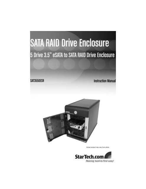
<strong>SATA</strong> <strong>RAID</strong> <strong>Drive</strong> <strong>Enclosure</strong><br />
5 <strong>Drive</strong> 3.5” e<strong>SATA</strong> to <strong>SATA</strong> <strong>RAID</strong> <strong>Drive</strong> <strong>Enclosure</strong><br />
SAT3550ESR<br />
Instruction Manual<br />
Actual product may vary from photo
FCC Compliance Statement<br />
This equipment has been tested and found to <strong>com</strong>ply with the limits for a Class B digital<br />
device, pursuant to part 15 of the FCC Rules. These limits are designed to provide<br />
reasonable protection against harmful interference in a residential installation. This<br />
equipment generates, uses and can radiate radio frequency energy and, if not installed<br />
and used in accordance with the instructions, may cause harmful interference to radio<br />
<strong>com</strong>munications. However, there is no guarantee that interference will not occur in a<br />
particular installation. If this equipment does cause harmful interference to radio or<br />
television reception, which can be determined by turning the equipment off and on, the<br />
user is encouraged to try to correct the interference by one or more of the following<br />
measures:<br />
• Reorient or relocate the receiving antenna.<br />
• Increase the separation between the equipment and receiver.<br />
• Connect the equipment into an outlet on a circuit different from that to which the<br />
receiver is connected.<br />
• Consult the dealer or an experienced radio/TV technician for help.<br />
Use of Trademarks, Registered Trademarks, and<br />
other Protected Names and Symbols<br />
This manual may make reference to trademarks, registered trademarks, and other<br />
protected names and/or symbols of third-party <strong>com</strong>panies not related in any way to<br />
<strong>StarTech</strong>.<strong>com</strong>. Where they occur these references are for illustrative purposes only and<br />
do not represent an endorsement of a product or service by <strong>StarTech</strong>.<strong>com</strong>, or an<br />
endorsement of the product(s) to which this manual applies by the third-party <strong>com</strong>pany in<br />
question. Regardless of any direct acknowledgement elsewhere in the body of this<br />
document, <strong>StarTech</strong>.<strong>com</strong> hereby acknowledges that all trademarks, registered<br />
trademarks, service marks, and other protected names and/or symbols contained in this<br />
manual and related documents are the property of their respective holders.
Table of Contents<br />
Instruction Manual<br />
Introduction . . . . . . . . . . . . . . . . . . . . . . . . . . . . . . . . . . . . . . . . . . . . . . . . . . . . .1<br />
Features . . . . . . . . . . . . . . . . . . . . . . . . . . . . . . . . . . . . . . . . . . . . . . . .1<br />
Before You Begin . . . . . . . . . . . . . . . . . . . . . . . . . . . . . . . . . . . . . . . . . . . . . . . . .1<br />
System Requirements . . . . . . . . . . . . . . . . . . . . . . . . . . . . . . . . . . . . .1<br />
Contents . . . . . . . . . . . . . . . . . . . . . . . . . . . . . . . . . . . . . . . . . . . . . . . .1<br />
Installation . . . . . . . . . . . . . . . . . . . . . . . . . . . . . . . . . . . . . . . . . . . . . . . . . . . . . .2<br />
Host Controller Installation . . . . . . . . . . . . . . . . . . . . . . . . . . . . . . . . . .2<br />
SiI 4726 Manager GUI Installation . . . . . . . . . . . . . . . . . . . . . . . . . . . .2<br />
Hardware Guide . . . . . . . . . . . . . . . . . . . . . . . . . . . . . . . . . . . . . . . . . .3<br />
Hard drive installation . . . . . . . . . . . . . . . . . . . . . . . . . . . . . . . . . . . . . .4<br />
Connecting the <strong>Drive</strong> <strong>Enclosure</strong> to the <strong>com</strong>puter . . . . . . . . . . . . . . . .4<br />
Configuration . . . . . . . . . . . . . . . . . . . . . . . . . . . . . . . . . . . . . . . . . . . . . . . . . . .5<br />
Introduction . . . . . . . . . . . . . . . . . . . . . . . . . . . . . . . . . . . . . . . . . . . . .5<br />
Status Window . . . . . . . . . . . . . . . . . . . . . . . . . . . . . . . . . . . . . . . . . . .6<br />
Elements of the Status window . . . . . . . . . . . . . . . . . . . . .6<br />
Basic Configuration . . . . . . . . . . . . . . . . . . . . . . . . . . . . . . . . . . . . . . .8<br />
Advanced Configuration . . . . . . . . . . . . . . . . . . . . . . . . . . . . . . . . . .11<br />
Multiple Volume Configuration . . . . . . . . . . . . . . . . . . . . . . . . . . . . . .13<br />
Manage Configuration files . . . . . . . . . . . . . . . . . . . . . . . . . . . . . . . .16<br />
Partition Configured Volumes . . . . . . . . . . . . . . . . . . . . . . . . . . . . . .18<br />
Administering the SAT3550ESR <strong>Drive</strong> <strong>Enclosure</strong> . . . . . . . . . . . . . . . . . . . . .20<br />
Configuring the SAFE Volume Rebuild Storage Policy . . . . . . . . . . .21<br />
Email Notification . . . . . . . . . . . . . . . . . . . . . . . . . . . . . . . . . . . . . . . .22<br />
Install New Firmware & Software . . . . . . . . . . . . . . . . . . . . . . . . . . .24<br />
Editing the UserConfig.xml<br />
Monitoring and Troubleshooting . . . . . . . . . . . . . . . . . . . . . . . . . . . . . . . . . . .27<br />
Storage Policies Glossary . . . . . . . . . . . . . . . . . . . . . . . . . . . . . . . . . . . . . . . .31<br />
Specifications . . . . . . . . . . . . . . . . . . . . . . . . . . . . . . . . . . . . . . . . . . . . . . . . . .33<br />
Technical Support . . . . . . . . . . . . . . . . . . . . . . . . . . . . . . . . . . . . . . . . . . . . . . .33<br />
Warranty Information . . . . . . . . . . . . . . . . . . . . . . . . . . . . . . . . . . . . . . . . . . . .33<br />
i
Introduction<br />
Instruction Manual<br />
Thank you for purchasing a <strong>StarTech</strong>.<strong>com</strong> 5 <strong>Drive</strong> 3.5” e<strong>SATA</strong> to <strong>SATA</strong> <strong>RAID</strong> <strong>Drive</strong><br />
<strong>Enclosure</strong>. A cost-effective storage solution, SAT3550ESR provides enhanced data<br />
protection, high-performance storage and plug-and-play functionality, making it a simple<br />
solution for professional or home users to replicate data and maintain data security.<br />
Features<br />
• Five separate drive bays maximize external storage capacity<br />
• Support for both 2.5” and 3.5” <strong>SATA</strong> hard drives<br />
• Single rear e<strong>SATA</strong> interface to host to manage access to each hard drive<br />
• Supports data transfer speeds up to 3 Gbps<br />
• Each hard drive bay is hot swappable<br />
• Dual 80mm internal fans for enhanced hard drive cooling<br />
Before You Begin<br />
System Requirements<br />
• x86 platform: An Intel Pentium 3 500MHz equivalent or faster<br />
• Mac platform: A Mac G4 500MHz or faster<br />
• CD-ROM drive (driver installation)<br />
• 64 MB RAM<br />
• 250 MB of available hard drive space<br />
• SVGA capable monitor<br />
• Mouse/pointing device<br />
• External <strong>SATA</strong> cable connection between Host <strong>com</strong>puter and SAT3550ESR<br />
• Microsoft Windows 2000/XP/Server 2003 or Mac OS X with latest updates<br />
Package Contents<br />
• 1 x External <strong>Drive</strong> <strong>Enclosure</strong> • 1 x <strong>Drive</strong>r/Application CD<br />
• 1 x 2m e<strong>SATA</strong> Cable • 1 x Power Cord<br />
• 1 x Instruction Manual<br />
• 1 x Screw Kit<br />
• 1 x PCI-Express 1x Host <strong>RAID</strong><br />
Controller Card<br />
1
Installation<br />
Instruction Manual<br />
Host Controller installation<br />
In order to provide a software and hardware link between the host <strong>com</strong>puter and the<br />
SAT3550ESR <strong>Drive</strong> <strong>Enclosure</strong>, it is required that the included PCI Express Host<br />
Controller be installed on the host <strong>com</strong>puter. You may also use another Host Controller,<br />
provided it features port multiplier support, however it is not guaranteed that all host<br />
controllers with port multiplier support are <strong>com</strong>patible with the drive enclosure.<br />
1. Insert the <strong>Drive</strong>r CD into your CD/DVD-ROM drive<br />
2. Power down the <strong>com</strong>puter, ensuring the system is unplugged and you are grounded.<br />
3. Remove the cover of your system (see your <strong>com</strong>puter's user manual for details, if<br />
necessary) and gently turn your <strong>com</strong>puter onto its side, so that the PCI Express<br />
expansion slot on the motherboard is facing upward.<br />
4. Locate an empty PCI Express slot and remove the metal plate that covers the<br />
corresponding rear bracket. You may need a Phillips screwdriver to perform this step.<br />
Retain the screw! You will need it to secure the card later.<br />
5. Gently insert the card into the empty slot, making sure it is firmly seated.<br />
6. Secure the card to the rear panel, using the screw you removed in Step 3.<br />
7. Power on the <strong>com</strong>puter. Once the operating system is fully booted, insert the <strong>Drive</strong>r<br />
CD (included) into the CD/DVD-ROM drive. You will notice several message<br />
balloons originating in the taskbar, indicating that the required drivers are being<br />
installed for the devices found.<br />
Once the card has been properly installed,<br />
you can verify that it is detected by the<br />
operating system by browsing to the<br />
device manager (i.e. Start - Control Panel<br />
- System - Hardware - Device Manager):<br />
SiI 3132<br />
<strong>SATA</strong>Link<br />
Controller<br />
Sil 4726 Manager GUI installation<br />
The SiI 4726 Manager GUI provides a convenient way to manage disks installed within<br />
the <strong>Drive</strong> <strong>Enclosure</strong>. To install the Sil 4726 Manager GUI:<br />
1. Locate the Setup.exe file, by browsing to the BT3045_Manager\<br />
SiI_4726_Graphic_User_Interface_V4.0.0.9 subfolder.<br />
2. Double-click on the Setup.exe file to begin installation. Follow the on-screen prompts<br />
to <strong>com</strong>plete installation.<br />
2
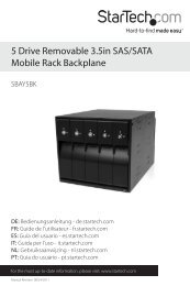
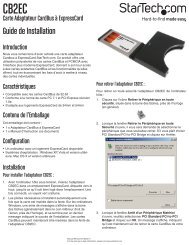
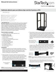
Hardware Guide<br />
Front Panel (closed)<br />
Instruction Manual<br />
Rear Panel<br />
Power<br />
Button<br />
Power Port<br />
e<strong>SATA</strong><br />
port<br />
Front Panel (open)<br />
Error Condition Indicator<br />
OK Indicator<br />
<strong>Drive</strong><br />
Bays<br />
Key Lock<br />
Front Panel<br />
Door<br />
3<br />
Safety latch
Hard drive installation<br />
Instruction Manual<br />
1. Open the Front Panel Door, exposing the individual <strong>Drive</strong> Bays.<br />
2. To remove one of the <strong>Drive</strong> Bays from the enclosure, slide the Safety Latch on the<br />
front panel of the bay, to the left. Gently press the cover of the <strong>Drive</strong> Bay until you<br />
hear a click, allowing the Retaining Arm to move freely. Grasp the Retaining Arm and<br />
pull the <strong>Drive</strong> Bay from the enclosure.<br />
3. Align the screwholes provided on the base of the <strong>Drive</strong> Bay, with the screws provided<br />
on the base of the hard drive. Secure the hard drive to the metal base of the <strong>Drive</strong><br />
Bay removed in step 2, using the included screws as necessary.<br />
4. Once the drive has been secured to the <strong>Drive</strong> Bay, replace the <strong>Drive</strong> Bay by gently<br />
sliding it into the empty slot, ensuring the <strong>Drive</strong> Bay is properly resting on the internal<br />
guide rails provided. The <strong>SATA</strong> data and power connectors located on the back of the<br />
hard drive should be in direct contact with the connectors located internally at the<br />
back of the enclosure.<br />
5. Gently press the Retaining Arm (see step 2) until it locks back in place, now flush with<br />
the other drive bays.<br />
6. Slide the Safety Latch to the right, to ensure that the installed drive is not accidentally<br />
released from the enclosure.<br />
7. Repeat steps 1-6, for the remaining hard drives you wish to install.<br />
8. Once you have secured each hard drive within the enclosure, close the Front Panel<br />
Door. Optionally, you can lock the Front Panel Door in place, using the keys provided,<br />
by turning the lock 1/4 turn in a clockwise direction.<br />
Connecting the <strong>Drive</strong> <strong>Enclosure</strong> to the <strong>com</strong>puter<br />
To connect the SAT3550ESR <strong>Drive</strong> <strong>Enclosure</strong> to the host <strong>com</strong>puter: Connect one<br />
end of a standard e<strong>SATA</strong> cable to the port located on the rear panel of the <strong>Drive</strong><br />
<strong>Enclosure</strong>; connect the remaining end of the e<strong>SATA</strong> cable to the e<strong>SATA</strong> port provided by<br />
the the newly installed host controller on the host <strong>com</strong>puter.<br />
To power the SAT3550ESR <strong>Drive</strong> <strong>Enclosure</strong>: Connect the female portion of the<br />
included power cable to the male power port located on the rear panel of the <strong>Drive</strong><br />
<strong>Enclosure</strong>. Connect the remaining end of the power cable to an available power outlet.<br />
Press and hold the Power button for three seconds, (located on the front of the <strong>Drive</strong><br />
<strong>Enclosure</strong>). Verify that the drives are detected by the operating system (in Windows, for<br />
example, browse to My Computer, where the newly attached drives should appear).<br />
4
Configuration<br />
Introduction<br />
Windows<br />
Instruction Manual<br />
1. Click on the Start button, and select All Programs. Click on Sil 4726 Manager to<br />
launch the configuration program.<br />
2. From the window that opens, you are able to monitor the status of the connected<br />
drives:<br />
Mac OS X<br />
1. Launch the Finder and locate the SiI 4726 program within the Applications - Utilities<br />
- SteelVine folder. Click the SiI 4726 icon to start the SiI 4726 Manager. If the launch<br />
sequence does not locate an active Daemon, a warning will appear; click OK to<br />
advance past the warning.<br />
2. You will be asked to enter the administrator password. Once you have done so, click<br />
OK to proceed.<br />
3. A notice will appear as the launch sequence attempts to start the Daemon. Click OK.<br />
If the Daemon fails to start, an error message will be displayed. Please follow the<br />
re<strong>com</strong>mendations in the error message to correct the problem.<br />
4. The window that will open (Status Window) allows you to monitor the status of the<br />
installed drives.<br />
5
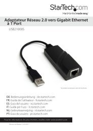
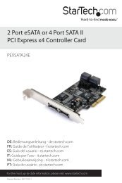
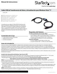
Status Window<br />
Instruction Manual<br />
The Status Window provides basic information pertaining to the installed drives and their<br />
respective configuration:<br />
1<br />
2<br />
3<br />
4<br />
1 Serial Number<br />
2<br />
3<br />
4<br />
System Status<br />
<strong>Drive</strong> Status<br />
Capacity Information<br />
Elements of the Status window<br />
System Status section<br />
Temp : Indicates the current internal temperature of the SAT3550ESR <strong>Drive</strong> <strong>Enclosure</strong><br />
Fan Speed : Indicates the system fan status. Use this data to monitor possible<br />
malfunctions<br />
<strong>Drive</strong> Status section<br />
Box Status : Indicates the drive status: Normal, Rebuilding, Unplugged, Needs<br />
Rebuild, New <strong>Drive</strong>, Wrong Slot<br />
<strong>Drive</strong> S/N : Shows the unique serial number assigned by the disk manufacturer<br />
Exp. S/N : Shows the expected serial number of the hard disk drive. The Daemon<br />
<strong>com</strong>pares the expected and actual drive serial numbers to detect when a<br />
drive’s status changes.<br />
6
Instruction Manual<br />
Capacity Information section<br />
Policy : Shows the storage policy configured for each volume.<br />
Total : Shows the <strong>com</strong>bined capacity of the volume.<br />
<strong>Drive</strong> # : Shows capacity information for each hard disk.<br />
Capacity : Shows the full amount of storage space (in GB) available on each hard disk.<br />
Volume : Shows the total volume capacity and the drive capacities assigned to each<br />
volume.<br />
File Menu<br />
Change Password : Opens a dialog to establish a new password.<br />
Scan Devices : Refreshes the status list details presented on the Status window.<br />
Change Connections : Opens a dialog to establish remote connections.<br />
Edit Menu<br />
Configure Box : Opens the Basic Configuration Wizard. From here, you can access the<br />
Advanced Configuration Wizard.<br />
Specify Policy : Opens the Rebuild Policy dialog.<br />
Specify Email Notification : Sends email notification for the selected items.<br />
Event Log : Opens the Event Log viewer.<br />
Specify Firmware : Opens the Firmware Selection dialog.<br />
Toolbar button functions<br />
Configure Box - Opens the Basic Configuration Wizard.<br />
Specify Policy : Opens the Rebuild Policy dialog<br />
Specify Email Notification : Sends email notification for the selected items<br />
Event Log : Opens the Event Log viewer<br />
Specify Firmware : Opens the Firmware Selection dialog<br />
7
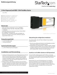
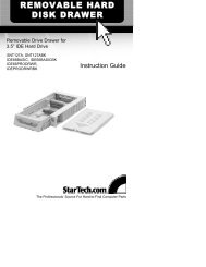
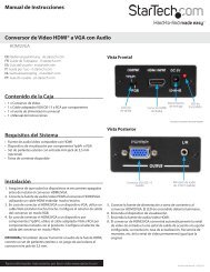
Basic Configuration<br />
Instruction Manual<br />
The following section details the Basic Configuration Wizard and explains how to<br />
configure volumes (virtual drives).<br />
Basic Configuration Wizard<br />
The SAT3550ESR Basic Configuration Wizard is accessible from the Status window<br />
and allows volume management. The Wizard defines volumes based on a selected<br />
storage policy. An end-user cannot modify volume counts or capacities. To protect<br />
against unintentional changes, the SAT3550ESR prompts for a password for first time<br />
access of the Wizard. The default password is admin. (For additional information on the<br />
default password, please see the section entitled Change Password.)<br />
1<br />
3<br />
2<br />
1 Storage Policy - Identifies available storage policies to assign to the<br />
SAT3550ESR configuration.<br />
2 Volume List - Shows Volume, Mode (storage policy) and Size details for<br />
created volumes. The total GBs Left field (beneath the volume<br />
list) displays the remaining capacity in GBs, for all installed hard<br />
disks.<br />
3 <strong>Drive</strong> Graph - Displays disk space for each hard disk drive. All space allocated<br />
to the same volume appears in a matching color. A hatch<br />
pattern indicates a proposed configuration and a solid block<br />
represents an existing volume. The Cap field beneath each<br />
drive in the drive graph shows the maximum capacity in GBs for<br />
that hard disk.<br />
Toolbar button functions<br />
Read a configuration from a file Reads a saved configuration so the end user<br />
can apply the configuration to the SAT3550ESR<br />
<strong>Drive</strong> <strong>Enclosure</strong>.<br />
8
Instruction Manual<br />
Write configuration from system to a file<br />
Restore configuration to last <strong>com</strong>mit<br />
Saves a configuration to a file on the<br />
host <strong>com</strong>puter.<br />
Cancels proposed changes<br />
Command buttons on the Basic Configuration Wizard<br />
To Advanced Mode : Opens the Advanced Configuration Wizard<br />
Apply : Submits configuration changes to the <strong>Drive</strong> <strong>Enclosure</strong>, and closes the<br />
Configuration Wizard.<br />
Cancel : Aborts the changes and closes the Configuration Wizard.<br />
Volume Configuration<br />
1. Select Configure Box<br />
from the Edit menu or<br />
click the Configure<br />
Box toolbar button<br />
to open the<br />
Configuration<br />
Wizard.<br />
2. When prompted, enter the administrator password. The default password is Admin.<br />
3. Select a storage policy in the<br />
Storage Policy frame, based<br />
on the following definitions:<br />
9
Instruction Manual<br />
***Basic Storage Policy Options:<br />
JBOD (bypass): Creates a logical volume for each physical hard disk.<br />
SAFE (<strong>RAID</strong> 1): Creates two volumes. For each volume, one hard disk is<br />
mirrored onto a second drive. Makes the remaining drive the<br />
Hot Spare for both volumes.<br />
BIG (Span): Concatenates all hard disks into a single volume.<br />
FAST (<strong>RAID</strong> 0) : Stripes Hard drives to increase storage operation speed.<br />
SAFE and BIG : Concatenates half of the available space on four hard disk<br />
drives and mirrors that half to the second half of the available<br />
space. Makes the remaining drive the Hot Spare.<br />
SAFE and FAST (<strong>RAID</strong> 1+0) : Creates one volume consisting of four hard<br />
drives (data is written to the mirrored disks in a<br />
striped format). Makes the remaining drive the<br />
Hot Spare.<br />
4. When prompted to acknowledge that the configuration change may result in data loss,<br />
click Yes to accept the configuration.<br />
5. Select Save to Config File from the File menu to save the configuration.<br />
6. Click Apply to create the selected configuration. The Volume display will close<br />
automatically and the Status window will refresh (within a minute or so).<br />
7. Partition the configured volume(s) to <strong>com</strong>plete the implementation. Please refer to the<br />
section entitled Partitioning Configured Volumes for further information.<br />
10
Instruction Manual<br />
Advanced Configuration<br />
The following section details how to use the Advanced Configuration Wizard to apply<br />
more than one storage policy to volumes in the SAT3550ESR <strong>Drive</strong> <strong>Enclosure</strong>.<br />
While the Basic Configuration provides six predefined storage policies to quickly<br />
configure the <strong>Drive</strong> <strong>Enclosure</strong>, the Advanced Configuration Wizard allows you to<br />
configure up to ten volumes, each with different storage policies and capacities.<br />
The Advanced Configuration Wizard is an extension of Basic mode that allows you to<br />
create two volumes (virtual drives) on each physical hard disk.<br />
Storage<br />
Policy<br />
<strong>Drive</strong><br />
Graph<br />
Volume<br />
List<br />
Advanced<br />
Controls<br />
Elements of the Advanced Configuration Wizard<br />
Storage Policy : Displays available storage policies that you can assign to volumes. The<br />
options are enabled after you create a new volume or select an existing<br />
volume to edit.<br />
Volume List : Displays Volume, Mode (storage policy) and size details for currently<br />
configured volumes. Select a volume to edit or delete. The Total GBs left<br />
field beneath the volume list displays the remaining capacity in gigabytes<br />
for all hard disks.<br />
<strong>Drive</strong> Graph : Displays disk space for each installed hard disk. All space allocated to the<br />
same volume appears in a matching color. A hatch pattern indicates a<br />
proposed configuration and a solid block indicates an existing volume.<br />
Advanced Controls : Permit volume creation and modification on each hard disk:<br />
The Hot Spare check box indicates space on this drive is allocated<br />
as rebuild space for the selected SAFE volume.<br />
11
Toolbar button functions<br />
Instruction Manual<br />
The Use check box indicates drive membership within a volume.<br />
The Slider specifies capacity allocated to a volume.<br />
Text Field displays the capacity specified by manipulating the slider.<br />
The Cap field displays the maximum capacity for the hard drive<br />
Vol# shows the virtual volume with which each hard disk drive is<br />
associated<br />
Read a configuration from a file<br />
Write system configuration to a file<br />
Restore configuration to last Commit<br />
Create a new volume<br />
Edit selected volume<br />
Delete selected volume<br />
Reads a saved configuration into the Advanced<br />
Configuration Wizard so you can apply the<br />
configuration to the <strong>Drive</strong> <strong>Enclosure</strong>. Available<br />
in Basic and Advanced modes.<br />
Saves a configuration to a file on the host<br />
<strong>com</strong>puter. Available in Basic and Advanced<br />
modes.<br />
Cancels proposed changes. Available in<br />
Basic and Advanced modes.<br />
Creates a new volume on which to set the storage policy<br />
and capacity. You can create up to 2 volumes on each<br />
hard disk drive (10 total).<br />
Permits the storage policy and capacity of an existing<br />
volume to be modified.<br />
Deletes the volume that is currently selected in the<br />
volume list.<br />
Delete all volumes<br />
Deletes all configured volumes.<br />
Copy configuration<br />
from other device in the<br />
system<br />
Copies the configuration of another SAT3550ESR to the<br />
current SAT3550ESR.<br />
Command buttons on the Advanced Configuration Wizard<br />
To Basic Mode : Opens the Basic Configuration Wizard.<br />
Update Volume : Applies the selected storage policy to a specific portion of a hard disk,<br />
as a proposed configuration.<br />
Cancel : Aborts the pending changes and returns the Wizard to the point where you can<br />
perform different advanced configuration functions.<br />
12
Instruction Manual<br />
Command buttons on the Advanced Configuration Wizard - Cont’d<br />
Apply : Submits configuration changes to the <strong>Drive</strong> <strong>Enclosure</strong>, closes the Wizard, and<br />
displays the updated configuration on the Status Window.<br />
Cancel : Aborts the in-progress changes and closes the Wizard.<br />
Multiple Volume Configuration<br />
The Advanced Configuration Wizard allows many <strong>com</strong>binations of storage policies and<br />
capacities. This procedure shows how to modify a basic SAFE configuration so that it<br />
contains several volumes, each with different storage policies. This example illustrates<br />
one possible <strong>com</strong>bination that allocates all of the system’s available capacity to:<br />
One 50-gigabyte (GB) SAFE volume on drives 0 and 1, with no reserved space for a Hot<br />
Spare.<br />
One FAST volume that uses the remaining capacity on drives 0 and 1.<br />
One BIG volume that uses all of the capacity on drives 2, 3, and 4.<br />
The same sequence of steps applies to any configuration you choose to implement; only<br />
the storage policy and capacity allocation vary for different configuration options.<br />
NOTE: Before reconfiguring an existing SAT3550ESR <strong>Drive</strong> <strong>Enclosure</strong> with a<br />
new configuration, backup the data. Use the Disk Management utility provided<br />
by your OS to delete all partitions - except the unallocated, un-initialized disk<br />
that represents the SteelVine processor. Once the configuration and partitioning<br />
of the new volumes has taken place, it is safe to restore the backed up data to<br />
the new configuration. See the section entitled Partitioning Configured<br />
Volumes for details.<br />
1. Click the Configure Box toolbar button to open the Basic Configuration Wizard.<br />
2. Click To Advanced Mode to open the Advanced Configuration Wizard.<br />
3. Select Delete all volumes from the toolbar.<br />
Click Delete All<br />
Volumes<br />
4. When prompted to confirm the deletion of the volumes, click Yes.<br />
5. Select Create a new volume from the toolbar.<br />
Click Create a<br />
new volume<br />
13
Instruction Manual<br />
Select SAFE (<strong>RAID</strong>1) as the Storage Policy. Click on the Use check boxes underneath<br />
<strong>Drive</strong>s 0 and 1. Move the slide to 50.<br />
Safe<br />
Mode<br />
Uncheck<br />
Hot Spare<br />
7. Click Update Volume.<br />
Move<br />
Slider<br />
8. When prompted whether to create a Hot Spare for the SAFE volume, click No. In<br />
some configurations, you may want the added redundancy of a Hot Spare. The goal<br />
of this example is to use all available system capacity to deliberately avoid the Hot<br />
Spare.<br />
9. Click the Create a New Volume toolbar button.<br />
Crosshatches<br />
identify<br />
allocated<br />
space for<br />
updated<br />
volumes<br />
Light, solid<br />
colors<br />
identify<br />
unallocated<br />
disk space<br />
10. Select the FAST radio button in the Storage Policy section.<br />
11. Select the Use check box beneath both <strong>Drive</strong> 0 and <strong>Drive</strong> 1.<br />
14
Instruction Manual<br />
12. Move the slider beneath <strong>Drive</strong> 0 all the way to the right to allocate the remaining<br />
capacity on the two drives to the FAST volume. If you wish, you can allocate less than<br />
the total remaining capacity to the new volume. However, doing so makes the<br />
unallocated capacity unavailable and unused.<br />
13. Click Update Volume.<br />
14. Click the Create a New Volume toolbar button.<br />
15. Select the BIG radio button in the Storage Policy section.<br />
16. Select the Use check box beneath <strong>Drive</strong> 2, <strong>Drive</strong> 3, and <strong>Drive</strong> 4 to allocate all of the<br />
remaining system capacity to the BIG volume.<br />
17. Click Update Volume.<br />
Please note: Only the last Volume listed (in the above example, Volume 2) can be<br />
edited. In order to edit Volume 1, Volume 2 must be deleted. In order to<br />
edit Volume 0, all Volumes must be deleted and the end-user will need to<br />
start with a New Volume.<br />
18. Click the Write Configuration for System to a File toolbar button to save the<br />
configuration.<br />
19. Click Update Volume to create the multi-volume configuration, close the Wizard, and<br />
will display the volumes in the Status window (within a minute or so):<br />
11. Partition the configured volumes to <strong>com</strong>plete the implementation. See the section<br />
entitled Partitioning Configured Volumes for details.<br />
15
Manage Configuration files<br />
Instruction Manual<br />
The Basic Configuration Wizard provides menus and icons to manage configuration<br />
files.<br />
The Read Config File <strong>com</strong>mand from the File menu in the Basic Configuration Wizard<br />
imports a configuration file so that the end-user can restore a previously saved<br />
configuration (storage policy).<br />
The Save to Config File <strong>com</strong>mand from the File menu in the Basic Configuration<br />
Wizard exports an SAT3550ESR <strong>Drive</strong> <strong>Enclosure</strong> configuration to a file.<br />
Each of the procedures in the Basic Configuration chapter prompts you to save a<br />
configuration file.<br />
Import a configuration file<br />
Please note: A configuration file must be saved and available, prior to being able to<br />
import it. Please see the section entitled Save a Configuration File for details.<br />
1. Select Configure Box from the Edit menu or click the Configure Box toolbar button<br />
in the Status window to open the Basic Configuration Wizard.<br />
2. Select Read Config File from the File menu in the Basic Configuration Wizard.<br />
3. Navigate to the required file and click Open to import it. The Basic Configuration<br />
Wizard provides notice of a successful import and graphically displays the imported<br />
volumes.<br />
4. Click OK to implement the imported configuration.<br />
16
Save a Configuration File<br />
Instruction Manual<br />
1. Select Configure Box from the Edit menu or click the Configure Box toolbar button<br />
in the Status window to open the Basic Configuration Wizard.<br />
2. Select Save to Config File from the File menu in the Basic Configuration Wizard.<br />
3. Navigate to the appropriate directory, specify<br />
a file name in the File Name text box, and<br />
click the Save button.<br />
17
Partition Configured Volumes<br />
Instruction Manual<br />
This chapter explains how to partition volumes after configuring them with the SiI 4726<br />
Manager software. The end-user must partition volumes for the host <strong>com</strong>puter’s operating<br />
system prior to storing data on the volumes. Please refer to the operating system<br />
documentation for further guidance.<br />
Windows<br />
Note: Before reconfiguring a volume, back up the data and delete previously<br />
defined partitions. Do not, however, delete the partition that represents the<br />
SteelVine processor (the “Not Initialized” disk with no capacity allocated to it).<br />
After the new volumes are configured and partitioned, the backed up data can<br />
be restored to the new configuration.<br />
1. Right-click the My Computer icon and select Manage from the pop-up window.<br />
2. From the Computer Management window select Disk Management under Storage<br />
to open Windows Disk Manager.<br />
Note: The Disk numbers in the Windows Disk Manager may be different from the Volume<br />
numbers shown in the SiI 4726 Manager Status window, the Basic Configuration<br />
Wizard, and the Advanced Configuration Wizard. Be sure to select the correct disk<br />
based on the expected disk capacity to create a partition.<br />
3. Right-click on the configured disk’s unallocated space and select New Partition. If the<br />
New Partition option is not available, select the disk and initialize it first. To do this,<br />
right-click on the disk item and select Initialize Disk.<br />
4. The Partition Wizard will launch. Click Next to begin.<br />
5. Select the Primary or Extended option and click Next.<br />
6. Specify the partition size. By default, the partition occupies the entire volume. Click<br />
Next to proceed.<br />
18
Instruction Manual<br />
7. Assign a drive letter or mount path and click Next.<br />
8. Select the appropriate file system, name the partition and click Next.<br />
9. Review the file system settings and click Finish to create the logical partition.<br />
10. Repeat steps 1 through 9 to partition any remaining disks you configured in the SiI<br />
4726 Manager software. Remember, do not partition the disk that represents the<br />
SteelVine processor.<br />
Mac OS X<br />
1. Launch Disk Utility from the Application > Utilities folder.<br />
2. Select a configured disk and click the Partition tab.<br />
Step<br />
2<br />
Step 4<br />
Step<br />
3<br />
Step 5<br />
Step 6<br />
Step 7<br />
3. Select 1 Partition from the Volume Scheme drop-down list.<br />
4. Enter a name for the volume in the Name field.<br />
5. Select Mac OS Extended (journaled) from the Format drop-down list.<br />
6. Specify the size of the partition in the Size field.<br />
7. Click the Partition button.<br />
19
Instruction Manual<br />
8. You will receive a warning that “Partitioning a disk will destroy all information on the<br />
disk”. Click Partition to acknowledge the warning. Disk Utility mounts the created<br />
partition and represents it with an icon on the desktop. The icon is labeled with the<br />
partition name.<br />
9. Repeat steps 1 through 8 to partition any remaining disks you configured in the SiI<br />
4726 Manager software. Remember, do not partition the 320.0 KB Config Disk that<br />
represents the SteelVine processor.<br />
Administering the SAT3550ESR <strong>Drive</strong> <strong>Enclosure</strong><br />
Change Password<br />
The SiI 4726 Manager software limits configuration access with a password prompt. The<br />
password information is stored locally on the server running the Daemon. The default<br />
password is admin.<br />
1. Select Change Password from the File menu.<br />
2. Enter the current password (or use admin if the default password has not yet been<br />
changed).<br />
3. Enter the new password of five or more characters in both fields.<br />
4. Click OK to implement the new password.<br />
Managing the Client Connection to the Daemon<br />
The SiI 4726 Manager software consists of two modules, the Daemon and the User<br />
Interface.<br />
The Daemon monitors the status of the <strong>Drive</strong> <strong>Enclosure</strong> and performs SAFE volume<br />
rebuilds. By default, the user interface attaches to a Daemon running on the same host<br />
to display the information gathered by the Daemon. The interface can be configured to<br />
display information tracked by a Daemon running on a remote host. Having the user<br />
interface remote to the Daemon allows remote monitoring for system fan and hard disk<br />
drive failures. Identification of a failed part allows the necessary repairs or replacement to<br />
be made before further <strong>com</strong>plications arise.<br />
20
Set up a remote connection<br />
Instruction Manual<br />
Before a remote connection can be established, the following conditions must be true:<br />
• The Daemon is installed and running on a host <strong>com</strong>puter connected to the<br />
<strong>Drive</strong> <strong>Enclosure</strong><br />
• The user interface is installed and running on a remote host <strong>com</strong>puter.<br />
• A TCP/IP connection can be established between the Daemon and the user<br />
interface. The Daemon listens for connections on TCP port 51115. Do not<br />
change this port number.<br />
1. In the Status window, select Change Connection from the File menu.<br />
2. Enter the hostname or IP address of the PC hosting the Daemon. Click OK. The User<br />
Interface will establish the requested connection and will display the information<br />
gathered by the remote Daemon in the Status window.<br />
Configuring SAFE Volume Rebuild Storage Policy<br />
A rebuild is initiated to restore data redundancy for a SAFE volume that has entered a<br />
vulnerable state. In a vulnerable state, one of the two mirrored disks goes offline or is<br />
inaccessible. Although the SAFE volume remains available during the rebuild process,<br />
the volume is susceptible to data loss through damage of the remaining disk until data<br />
redundancy is restored through a rebuild. Host access takes precedence over the rebuild<br />
process. If continuing to use the SAFE volume during the rebuild, the rebuild process will<br />
take a longer time to <strong>com</strong>plete.<br />
Please note that the Rebuild feature also applies to other SAFE policies such as SAFE<br />
and BIG, and SAFE and FAST.<br />
What happens during a rebuild?<br />
The rebuild process restores data redundancy by first utilizing space allocated for a Hot<br />
Spare. In case Hot Spare space does not exist or has already been rebuilt, the SteelVine<br />
processor rebuilds to empty space on a hard disk, other than the one containing<br />
vulnerable data. Following a rebuild, it is not necessary to designate space to a Hot<br />
Spare for a subsequent rebuild to occur.<br />
With Automatic Rebuild and Immediate Rebuild options selected, the Daemon<br />
automatically initiates an immediate rebuild. If the end-user wants the Daemon to delay<br />
the rebuild until after the first write to the SAFE volume, select the Rebuild Only If<br />
Needed option. The latter setup allows temporary removal of a hard disk drive without<br />
requiring a rebuild. To minimize the possibility of data loss, the rebuild process should be<br />
set up to start immediately. With Manual Rebuild selected, the end-user decides when to<br />
initiate rebuild following a rebuild prompt. Unless the SiI 4726 Manager and the <strong>Drive</strong><br />
21
Instruction Manual<br />
<strong>Enclosure</strong> are actively monitored, the Automatic Rebuild should be set up to minimize<br />
the possibility of data loss.<br />
Please Note: In case No is selected in response to a rebuild prompt, select Scan<br />
Devices from the File menu of the Status window to trigger a new prompt.<br />
Please Note: Once the Daemon rebuilds to a designated Hot Spare, a designated Hot<br />
Spare will not exist.<br />
Configure a rebuild<br />
1. Select Specify Policy from the Edit menu of the Status window.<br />
2. Select one of the following policy options:<br />
• The Manual Rebuild radio button requires a user to manually initiate a rebuild<br />
of the volume<br />
• The Automatic Rebuild option forces the Daemon to initiate the rebuild<br />
process automatically and minimize the possibility of data loss.<br />
3. If the Automatic Rebuild option is selected, the end-user will have the following<br />
additional choices:<br />
• Immediate Rebuild causes the Daemon to rebuild immediately following<br />
detection of an offline hard disk drive.<br />
• Rebuild Only If Needed delays the rebuild for a SAFE volume with an<br />
offline hard disk drive until the write occurs to the SAFE volume.<br />
4. Click the Accept button to <strong>com</strong>mit the selected options.<br />
Email Notification<br />
The Email Notification feature allows an end-user or administrator to have the SiI 4726<br />
Manager send an email if any of the following conditions/situations occur:<br />
• Partition Rebuild Start<br />
• System Fan Too Slow<br />
• Partition Rebuild Complete<br />
• Power Supply FanToo Slow<br />
• <strong>Drive</strong> Inserted<br />
• Partition Rebuild Resume<br />
• Partition Verify Start<br />
• No Boxes Found<br />
• Partition Verify Complete<br />
• Box Removed<br />
• <strong>Drive</strong> Unplugged<br />
• Temperature Too High<br />
Each of the above conditions can be customized for sending options as well as the<br />
message that is sent. Please see an example of the Setup Email Notification screen on<br />
the following page.<br />
22
Instruction Manual<br />
Setup E-mail Notification<br />
Setting-up Email Notification<br />
1. The box available for the SMTP Server Name can be left blank. The SiI 4726 Manager<br />
software will perform a DNS lookup and automatically find the correct address.<br />
2. The box available for the SMTP Server Port# uses Port 25 as a default.<br />
3. The From, To, and CC boxes are for specifying the intended receivers of the condition<br />
notifications. Note: In the From: box, the end-user should type in his/her own email<br />
address.<br />
4. Select Test Email at the bottom of the screen to verify that you have correctly set-up<br />
the email portions of this feature.<br />
5. The Email Notification feature also allows an end-user to customize a message for<br />
each of the line items (of which each has its own default message already built in). For<br />
instance, if the end-user wants to edit the message for <strong>Drive</strong> Unplugged...<br />
a) Click on the Message box:<br />
b) The following message will appear:<br />
SiI4726: $B<br />
<strong>Drive</strong> Slot: #$DN<br />
Temperature: $T<br />
System Fan Speed: $SF<br />
Power-Supply Fan Speed: $PSF<br />
The drive was unplugged.<br />
23
Instruction Manual<br />
c) The message information can be customized to suit the end-user’s needs.<br />
The Daemon can extract the following data from the SiI 4726 hardware:<br />
$B - Box Serial Number<br />
$DS - <strong>Drive</strong> Serial Number<br />
$DN - <strong>Drive</strong> ID [slot #]<br />
$V - Current Volume<br />
$T - Current Temperature<br />
$SF - System Fan OK Flag<br />
$PSF - Power Supply Fan OK Flag<br />
d) If there is information that the end-user would like included in the error<br />
message, it can be entered by typing in a selected message code listed<br />
above.<br />
For instance: to put in the Box Serial Number, type in the descriptive text<br />
followed by the message code as demonstrated below.<br />
SiI4726: $B<br />
<strong>Drive</strong> Slot: #$DN<br />
Temperature: $T<br />
System Fan Speed: $SF<br />
Power-Supply Fan Speed: $PSF<br />
Box Serial Number: $B<br />
The drive was unplugged.<br />
Install New Firmware & Software<br />
Warning: Do not power off or access the <strong>Drive</strong> <strong>Enclosure</strong> while upgrading<br />
firmware. Please note that this process may take several minutes.<br />
1. Click the Specify Firmware toolbar button or select Specify Firmware from the Edit<br />
menu of the Status window. The Firmware Selection dialog displays all of the<br />
SAT3550ESR <strong>Drive</strong> <strong>Enclosure</strong>s attached to the host, the integrated circuit (IC)<br />
revision, and the current firmware installed on each <strong>Drive</strong> <strong>Enclosure</strong> (assuming more<br />
than one SAT550ESR is in use).<br />
2. Select the SiI 4726 <strong>Drive</strong> <strong>Enclosure</strong> that requires a firmware upgrade.<br />
3. Click the Browse button next to the Update Firmware from File text box, navigate to<br />
the new firmware file you wish to load from a CD or hard disk drive, and select the .bin<br />
file.<br />
4. Click Install Firmware to begin the upgrade.<br />
24
Instruction Manual<br />
5. Click OK to dismiss a message box that states the firmware was successfully<br />
downloaded.<br />
Editing the UserConfig.xml<br />
The UserConfig.xml file is used to define the Status Screen Title Bar and allow<br />
configuration of the Policy Change as well as the Advanced Configuration features.<br />
The UserConfig.xml file can be found in the following location:<br />
C:\Program Files\SiI4726\SiI 4726 Manager\SiI 4726 Config<br />
To edit this file, Right Click on the file name, select Open With, and select Notepad.<br />
Once opened, the following will be displayed:<br />
As an example, to change the Status Screen Title Bar:<br />
Change the line that reads:<br />
SiI 4726 Manager<br />
To:<br />
Your Company Name<br />
In order to display:<br />
The‘AllowPolicyChanges’–True–turns on the Policy feature. If the end-user changes the<br />
XML tag value to False, the Policy Icon will not appear in the GUI and the feature will not<br />
be available.<br />
For example:<br />
True<br />
False<br />
25
Instruction Manual<br />
The ‘AllowAdvancedConfig’–True–turns on the Advanced Config feature. If the enduser<br />
changes the XML tag value to False, the general Configure feature will still be<br />
available, but the Advanced button (inside the Configuration feature) will not be<br />
available:<br />
True<br />
False <br />
Please Note: If the file is missing from the working directory, the GUI will allow both<br />
policy changes and advanced mode, as well as the status screen title to be set to<br />
“Sil4726”. If there are any errors in the XML tag value, the Advanced Configuration<br />
button will not be available in the Configuration Setup.<br />
If there is an error in the XML tag value, a pop-up window will appear, displaying the<br />
error and the tag where it can be found.<br />
Creating a Splash Screen<br />
The <strong>Drive</strong> <strong>Enclosure</strong>/SiI 4726 Manager software can further be customized by creating a<br />
personalized splash screen:<br />
1. Create the logo for your splash screen – there are no image size limitations.<br />
2. Save the logo as ‘UserLogo.xpm’ (The .xpm file type is UNIX based)<br />
3. Put the UserLogo.xpm file in the following location:<br />
C:\Program Files\SiI4726\SiI 4726 Manager\SiI 4726 Config<br />
The splash screen will <strong>com</strong>e up each time the end-user starts the SiI 4726 Manager<br />
software. It will stay up for 2 seconds.<br />
26
Instruction Manual<br />
Monitoring and Troubleshooting<br />
Monitoring drive status<br />
The color of the drives in the Status window indicates the status of the hard disk drives:<br />
Color State Description Resolution<br />
Green Normal <strong>Drive</strong> is active.<br />
Red<br />
Gray or<br />
Red<br />
Needs Rebuild<br />
Unplugged<br />
<strong>Drive</strong> is in a failed<br />
state. That is, a write<br />
has occurred to a<br />
SAFE volume while<br />
the disk drive was<br />
offline.<br />
<strong>Drive</strong> is offline or<br />
unplugged. The<br />
background will<br />
appear red after a<br />
write to<br />
the volume.<br />
Light Blue New drive New drive.<br />
Yellow Rebuilding <strong>Drive</strong> is being rebuilt.<br />
Purple Wrong slot<br />
There is a mismatch<br />
between the Serial #<br />
and Expected Serial<br />
# because a hard<br />
disk drive has been<br />
installed into the<br />
wrong bay.<br />
Verify the disk is<br />
securely in the bay.<br />
Otherwise, replace<br />
as necessary.<br />
Install the correct<br />
disk drive into the<br />
bay.<br />
Monitoring temperature<br />
The following colors indicate temperature status.<br />
Color Description Resolution<br />
Green<br />
Temperature is normal.<br />
Yellow<br />
Red<br />
Temperature is greater than<br />
50°C (122° F).<br />
Temperature is greater than<br />
53° C (127° F).<br />
Remove object(s) that interfere<br />
with airflow around the <strong>Drive</strong><br />
<strong>Enclosure</strong><br />
Ensure constant airflow around<br />
the <strong>Drive</strong> <strong>Enclosure</strong>. If there is no<br />
airflow, replace the fan. Identify<br />
the drive causing the temperature<br />
increase and replace it.<br />
27
Instruction Manual<br />
Monitoring fan status<br />
Color Value Description Resoluti<br />
Green<br />
System + PS<br />
Both system and<br />
power supply fans<br />
are functioning<br />
within limits.<br />
Red<br />
Red<br />
Red<br />
System<br />
PS<br />
System + PS<br />
The system fan is<br />
not spinning or<br />
spinning is slower<br />
than expected.<br />
The power supply<br />
fan is not spinning<br />
spinning slower<br />
than expected.<br />
Both system and<br />
power supply fans<br />
are not spinning or<br />
spinning slower<br />
than expected.<br />
Repair<br />
required.<br />
Review Event Logs<br />
Event logs are helpful for troubleshooting and locating a system malfunction.<br />
1. Select Event Log from the Edit menu in the Status window.<br />
2. The Event Log screen displays a list of events in a tabular format. The Date column<br />
displays the date and time of the event. The Box SN and <strong>Drive</strong> SN columns display<br />
the respective serial numbers for the event. The <strong>Drive</strong> Manufacturer column displays<br />
vendor information. The Message column gives an event description.<br />
3. Click Refresh to update the log or click Close to close the log.<br />
28
Front Panel LED Indicators<br />
Instruction Manual<br />
Each disk drive and the host connection have two LEDs to indicate drive status and/or<br />
host <strong>com</strong>munication status. LED 0 is on the left and is typically blue; LED 1 is on the<br />
right and is typically green. In addition, there is one error-condition LED, labeled ‘!’ and<br />
the SAT3550ESR power on indicator OK.<br />
Error<br />
Condition<br />
OK<br />
LED<br />
LED 0<br />
LED 1<br />
When SAT3550ESR is powered on, the host scans the disks in sequence, as indicated<br />
by a brief flash of lights on LED 1. Once the host scan is <strong>com</strong>plete, LED 1 is lit for each<br />
drive present. During disk operations, LED 0 flashes as data is transferred to and from<br />
the drive and the host.<br />
If a SAFE volume is being rebuilt, LED 1 blinks slowly on both mirrored disks.<br />
Table 15 Status Indicators for 0 and 1 LEDs<br />
LED 0 LED 1 Description<br />
Off Off Power on, no device attached<br />
Off<br />
On<br />
On Blink Rebuild<br />
Blink Blink Error<br />
PHY <strong>com</strong>munication established<br />
(Activity = LED0 On)<br />
29
Status Indicators for ! and OK LEDs<br />
Instruction Manual<br />
Off<br />
On<br />
! OK Description<br />
On<br />
Startup or ON<br />
indication. OK LED<br />
will flash during<br />
reset and<br />
will remain green in<br />
all other cases.<br />
ERROR. The‘!’LED<br />
will light as a result<br />
of an EEPROM<br />
error during<br />
boot or following a<br />
runtime error.<br />
30
Storage Policies Glossary<br />
Instruction Manual<br />
SAT3550ESR provides the following storage policies, for mapping physical to virtual<br />
drives. You can use the Basic Configuration Wizard or the Advanced Configuration<br />
Wizard to choose from these policies. It is important to choose a suitable policy to make<br />
the best use of available storage.<br />
JBOD<br />
SAFE<br />
This storage policy grants the host <strong>com</strong>puter direct access to a<br />
physical disk drive. With JBOD (Just a Bunch of Disks), the<br />
number of available virtual drives is equal to the number of<br />
physical drives. JBOD is also called the bypass mode because<br />
the host bypasses the virtualization engine to access the drive<br />
directly.<br />
This storage policy stores all data in duplicate on separate<br />
hard disk drives in order to prevent data loss due to drive<br />
failure. At least two hard disk drives mirror each other at all<br />
times, equivalent to <strong>RAID</strong> 1. Every write operation goes to both<br />
drives. SAFE provides the highest level of data protection, but<br />
halves the amount of storage space because all data must be<br />
stored twice.<br />
To implement the SAFE storage policy, the Basic<br />
Configuration Wizard creates two volumes. Each volume<br />
consists of two hard disk drives that mirror each other. The<br />
remaining hard disk drive is specified as a Hot Spare for both<br />
volumes.<br />
BIG<br />
This storage policy concatenates multiple physical hard disk<br />
drives, treating them as one large volume, in turn allowing you<br />
to increase logical volume size beyond the capacity of<br />
individual hard disk drives.<br />
BIG provides the maximum amount of storage space, but no<br />
additional data redundancy.<br />
FAST<br />
In the FAST storage policy, I/O processing is balanced evenly<br />
to all drives in a method known as striping, equivalent to <strong>RAID</strong><br />
0. Striping increases storage operation speed by using several<br />
disk drives in parallel, while each portion of data is divided into<br />
segments that are written to different disks simultaneously.<br />
Striping provides improved performance but does not enhance<br />
reliability because there is no way to retrieve or reconstruct<br />
data stored on a failed drive. To implement the FAST storage<br />
policy, the Basic Configuration Wizard creates a single<br />
volume of four hard disk drives in a striped format. The<br />
remaining hard disk drive is designated as a standalone<br />
volume using the BIG storage policy.<br />
31
SAFE and BIG<br />
Instruction Manual<br />
A storage policy in which one-half of the available storage<br />
space is concatenated, while the other half mirrors the first half<br />
to provide full data redundancy.<br />
In the SAFE and BIG storage policy, the Basic Configuration<br />
Wizard mirrors the concatenated disks to create a volume<br />
consisting of four disk drives, designating the remaining hard<br />
disk drive as a Hot Spare.<br />
SAFE and FAST<br />
Also classified as <strong>RAID</strong> 10 by some industry standards, a<br />
storage policy in which an array of stripes is created. Each strip<br />
consists of two mirrored drives. SAFE and FAST provide the<br />
I/O load balancing features of striping and the added reliability<br />
of mirrored data, equivalent to <strong>RAID</strong> 1+0. Data are<br />
written to mirrored disks in a striped format.<br />
In the SAFE and FAST storage policy, data is written to<br />
mirrored disks in a striped format. The Basic Configuration<br />
Wizard creates a virtual drive consisting of four hard disk<br />
drives, designating the remaining drive as a Hot Spare.<br />
Volume<br />
One or more hard disk drives are unused during normal<br />
operation and are configured to be a spare. If an active drive in<br />
a SAFE volume fails, the data on the remaining hard disk drive<br />
is duplicated onto the Hot Spare to regain redundancy.<br />
All SAFE volumes can have a designated Hot Spare<br />
Hot Spare<br />
A virtual or logical drive <strong>com</strong>prised of one or more physical<br />
hard disk drives. Once you create a volume, the operation<br />
system uses and maintains the volume as if it were a single<br />
physical disk drive, allowing software to over<strong>com</strong>e size<br />
restrictions imposed by physical disk drives.<br />
Daemon<br />
Component of the Controller Configuration Utility responsible<br />
for status tracking and SAFE volume rebuilds.<br />
32
Instruction Manual<br />
Specifications<br />
Regulatory Certifications<br />
Bus Type<br />
Form Factor<br />
Connectors<br />
LED indicators<br />
Power<br />
Controller Card<br />
FCC, CE, UL, RoHS<br />
e<strong>SATA</strong><br />
3.5 inch <strong>SATA</strong> HD <strong>Drive</strong> bays<br />
<strong>Enclosure</strong>: e<strong>SATA</strong> 7 pin<br />
One per <strong>Drive</strong> (presence and activity)<br />
Host connection(presence & activity)<br />
Fault indication<br />
Power indication<br />
Internal 200W Power Supply<br />
e<strong>SATA</strong> PCI-Express Host <strong>RAID</strong> card<br />
Maximum Data Transfer Rate<br />
e<strong>SATA</strong> 3 Gb/s<br />
OS Support<br />
Windows: 98SE (Setup driver CD incl.), ME, 2000,<br />
XP, Vista MAC OS X (10.3.or later)<br />
Dimensions 300 x 150 x 230 mm (L W H)<br />
Weight<br />
5 kg<br />
Technical Support<br />
<strong>StarTech</strong>.<strong>com</strong>’s lifetime technical support is an integral part of our <strong>com</strong>mitment to provide<br />
industry-leading solutions. If you ever need help with your product, visit<br />
www.startech.<strong>com</strong>/support and access our <strong>com</strong>prehensive selection of online tools,<br />
documentation, and downloads.<br />
Warranty Information<br />
This product is backed by a one-year warranty. In addition, <strong>StarTech</strong>.<strong>com</strong> warrants its<br />
products against defects in materials and workmanship for the periods noted, following<br />
the initial date of purchase. During this period, the products may be returned for repair, or<br />
replacement with equivalent products at our discretion. The warranty covers parts and<br />
labor costs only. <strong>StarTech</strong>.<strong>com</strong> does not warrant its products from defects or damages<br />
arising from misuse, abuse, alteration, or normal wear and tear.<br />
Limitation of Liability<br />
In no event shall the liability of <strong>StarTech</strong>.<strong>com</strong> Ltd. and <strong>StarTech</strong>.<strong>com</strong> USA LLP (or their<br />
officers, directors, employees or agents) for any damages (whether direct or indirect,<br />
special, punitive, incidental, consequential, or otherwise), loss of profits, loss of business,<br />
or any pecuniary loss, arising out of or related to the use of the product exceed the<br />
actual price paid for the product. Some states do not allow the exclusion or limitation of<br />
incidental or consequential damages. If such laws apply, the limitations or exclusions<br />
contained in this statement may not apply to you.<br />
33
About <strong>StarTech</strong>.<strong>com</strong><br />
<strong>StarTech</strong>.<strong>com</strong> is “The Professionals’ Source for Hard-to-Find Computer<br />
Parts”. Since 1985, we have been providing IT professionals with the<br />
quality products they need to <strong>com</strong>plete their solutions. We offer an<br />
unmatched selection of <strong>com</strong>puter parts, cables, server management<br />
solutions and A/V products and serve a worldwide market through our<br />
locations in the United States, Canada, the United Kingdom and Taiwan.<br />
Visit www.startech.<strong>com</strong> for <strong>com</strong>plete information about all our products<br />
and to access exclusive interactive tools such as the Parts Finder and the<br />
KVM Reference Guide. <strong>StarTech</strong>.<strong>com</strong> makes it easy to <strong>com</strong>plete almost<br />
any IT solution. Find out for yourself why our products lead the industry in<br />
performance, support, and value.<br />
Revised: 28 September 2007