Report PDF (3.7 MB) - USGS
Report PDF (3.7 MB) - USGS
Report PDF (3.7 MB) - USGS

You also want an ePaper? Increase the reach of your titles
YUMPU automatically turns print PDFs into web optimized ePapers that Google loves.
10 Surrogate Technologies to Estimate Suspended Sediment, Clearwater River, Idaho, and Snake River, Wash., 2008–10<br />
100<br />
90<br />
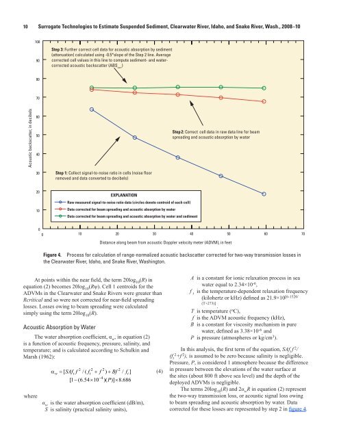
Step 3: Further correct cell data for acoustic absorption by sediment<br />
(attenuation) calculated using -0.5*slope of the Step 2 line. Average<br />
corrected cell values in this line to compute sediment- and watercorrected<br />
acoustic backscatter (ABS corr<br />
)<br />
80<br />
70<br />
Acoustic backscatter, in decibels<br />
60<br />
50<br />
40<br />
Step 2: Correct cell data in raw data line for beam<br />
spreading and acoustic absorption by water<br />
30<br />
Step 1: Collect signal-to-noise ratio in cells (noise floor<br />
removed and data converted to decibels)<br />
20<br />
10<br />
EXPLANATION<br />
Raw measured signal-to-noise ratio data (circles denote centroid of each cell)<br />
Data corrected for beam spreading and acoustic absorption by water<br />
Data corrected for beam spreading and acoustic absorption by water and sediment<br />
0<br />
0 10 20 30 40 50 60 70<br />
Distance along beam from acoustic Doppler velocity meter (ADVM), in feet<br />
Figure 4. Process for calculation of range-normalized acoustic backscatter corrected for two-way transmission losses in<br />
the Clearwater River, Idaho, and Snake River, Washington.<br />
At points within the near field, the term 20log 10<br />
(R) in<br />
equation (2) becomes 20log 10<br />
(Rψ). Cell 1 centroids for the<br />
ADVMs in the Clearwater and Snake Rivers were greater than<br />
Rcritical and so were not corrected for near-field spreading<br />
losses. Losses owing to beam spreading were calculated<br />
simply using the term 20log 10<br />
(R).<br />
Acoustic Absorption by Water<br />
The water absorption coefficient, α w<br />
, in equation (2)<br />
is a function of acoustic frequency, pressure, salinity, and<br />
temperature; and is calculated according to Schulkin and<br />
Marsh (1962):<br />
2 2 2 2<br />
α w = SAf t f f t + f + Bf f t<br />
−4<br />
[ /( ) / ]<br />
[ 1− ( 654 . × 10 )( P)] × 8.<br />
686<br />
where<br />
α w<br />
is the water absorption coefficient (dB/m),<br />
S is salinity (practical salinity units),<br />
tac13-0799_fig 04<br />
(4)<br />
A is a constant for ionic relaxation process in sea<br />
water equal to 2.34×10 -6 ,<br />
f t<br />
is the temperature-dependent relaxation frequency<br />
(kilohertz or kHz) defined as 21.9×10 [6-1520/<br />
(T+273)]<br />
,<br />
T is temperature ( o C),<br />
f is the ADVM acoustic frequency (kHz),<br />
B is a constant for viscosity mechanism in pure<br />
water, defined as 3.38×10 -6 , and<br />
P is pressure (atmospheres or kg/cm 3 ).<br />
In this analysis, the first term of the equation, SAf t<br />
f 2 /<br />
(f t<br />
2<br />
+f 2 ), is assumed to be zero because salinity is negligible.<br />
Pressure, P, is considered 1 atmosphere because the difference<br />
in pressure between the elevations of the water surface at<br />
the sites (about 800 ft above sea level) and the depth of the<br />
deployed ADVMs is negligible.<br />
The terms 20log 10<br />
(R) and 2α w<br />
R in equation (2) represent<br />
the two-way transmission loss, or acoustic signal loss owing<br />
to beam spreading and acoustic absorption by water. Data<br />
corrected for these losses are represented by step 2 in figure 4.