Report PDF (3.7 MB) - USGS
Report PDF (3.7 MB) - USGS
Report PDF (3.7 MB) - USGS

Create successful ePaper yourself
Turn your PDF publications into a flip-book with our unique Google optimized e-Paper software.
Methods 11<br />
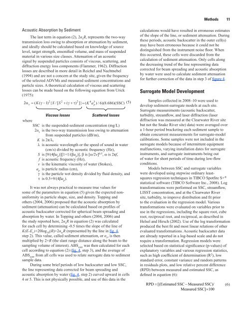
Acoustic Absorption by Sediment<br />
The last term in equation (2), 2α s<br />
R, represents the two-way<br />
transmission loss owing to absorption or attenuation by sediment,<br />
and ideally should be calculated based on knowledge of source<br />
level, target strength, ensonified volume, and mass of suspended<br />
material in various size classes. Attenuation of an acoustic<br />
signal by suspended particles consists of viscous, scattering, and<br />
diffraction energy loss components (Flammer, 1962). Diffraction<br />
losses are described in more detail in Reichel and Nachtnebel<br />
(1994) and are not a concern at the study site, given the frequency<br />
of the selected ADVMs and measured sediment concentrations and<br />
particle sizes. A theoretical calculation of viscous and scattering<br />
losses can be made based on the following equation from Urick<br />
(1975):<br />
2 2 2 4 3<br />
2α = ( K( γ− 1){ S /[ S + ( γ+ τ) ]} + ( K a )/ 6)(. 8 686)( SSC)<br />
(5)<br />
s<br />
Viscous losses<br />
Scattered losses<br />
where<br />
SSC is the suspended-sediment concentration (mg/L)<br />
2α s<br />
is the two-way transmission loss owing to attenuation<br />
from suspended particles (dB/m),<br />
K is 2π/λ,<br />
λ is acoustic wavelength or the speed of sound in water<br />
(cm/s) divided by acoustic frequency (Hz),<br />
S is [9/(4βa p<br />
)][1+1/(βa p<br />
)], β is [ω/2v] 0.5 , ω is 2πf,<br />
f is acoustic frequency (Hz),<br />
v is the kinematic viscosity of water (Stokes),<br />
a p<br />
is particle radius (cm),<br />
γ is the particle wet density divided by fluid density, and<br />
τ is 0.5+9/(4βa p<br />
).<br />
It was not always practical to measure true values for<br />
some of the parameters in equation (5) given the expected nonuniformity<br />
in particle shape, size, and density. Topping and<br />
others (2004, 2006) proposed that the acoustic absorption by<br />
sediment (attenuation) can be calculated based on profiles of<br />
acoustic backscatter corrected for spherical beam spreading and<br />
absorption by water. In Topping and others (2004, 2006) and<br />
the study reported here, 2α s<br />
R in equation (2) was calculated<br />
for each cell by determining -0.5 times the slope of the line of<br />
K(E-E r<br />
)+20log 10<br />
(R)+2α w<br />
R (represented by the line in fig. 4,<br />
step 2). This value, called sediment attenuation, or α s<br />
, is then<br />
multiplied by 2×R (the slant range distance along the beam to the<br />
sampling volume of interest). ABS corr<br />
was then calculated for each<br />
cell according to equation (2) (fig. 4, step 3), and the average of<br />
ABS corr<br />
from all cells was used to relate surrogate data to sediment<br />
sample data.<br />
During some brief periods of low backscatter and low SSC,<br />
the line representing data corrected for beam spreading and<br />
acoustic absorption by water (fig. 4, step 2) curved upward in cells<br />
4 or 5. This is not physically possible, and use of this data in the<br />
p<br />
calculations would have resulted in erroneous estimates<br />
of the slope of the line, or sediment attenuation. During<br />
these periods, acoustic backscatter in the outer cell(s)<br />
may have been erroneous because it could not be<br />
distinguished from the instrument noise floor. When<br />
this occurred, these cells were discarded from the<br />
calculation of sediment attenuation. Only cells along<br />
the decreasing trend of the line representing data<br />
corrected for beam spreading and acoustic absorption<br />
by water were used to calculate sediment attenuation<br />
for further correction of the data in step 3 of figure 4.<br />
Surrogate Model Development<br />
Samples collected in 2008–10 were used to<br />
develop sediment-surrogate models at each site.<br />
Surrogate measurements (acoustic backscatter,<br />
turbidity, streamflow, and laser diffraction (laser<br />
diffraction was measured at the Clearwater River site<br />
but not the Snake River site) data) were averaged over<br />
a 1-hour period bracketing each sediment sample to<br />
obtain concurrent measurements for surrogate-model<br />
calibrations. Some samples were not included in the<br />
surrogate models because of intermittent equipment<br />
malfunctions, varying installation dates for surrogate<br />
instruments, and surrogate instruments being out<br />
of water for short periods of time during low-flow<br />
conditions.<br />
Models between SSC and surrogate variables<br />
were developed using stepwise ordinary leastsquares<br />
regression techniques in TIBCO Spotfire S+ ®<br />
statistical software (TIBCO Software Inc., 2008). Log<br />
transformations were performed on SSC, streamflow,<br />
LISST concentration, and at the Clearwater River<br />
site, turbidity, to improve distribution and fit prior<br />
to the evaluation in the regression model. Various<br />
transformations were evaluated on variables prior to<br />
use in the regressions, including the square root, cube<br />
root, reciprocal root, and reciprocal, as described in<br />
Helsel and Hirsch (2002). Use of the log transformation<br />
produced the best fit and most linear relations of other<br />
evaluated transformations. Acoustic backscatter data<br />
are already reported in a log-based scale and do not<br />
require a transformation. Regression models were<br />
selected based on statistical significance (p-values) of<br />
explanatory variables and various regression statistics,<br />
such as high coefficient of determination (R 2 ), low<br />
standard error, constant variance and random patterns<br />
in residuals plots, and low relative percent difference<br />
(RPD) between measured and estimated SSC, as<br />
defined in equation (6):<br />
RPD = [( Estimated SSC −Measured SSC)/<br />
Measured SSC] × 100<br />
(6)