XStream⢠Advanced Programming & Configuration
XStream⢠Advanced Programming & Configuration
XStream⢠Advanced Programming & Configuration

You also want an ePaper? Increase the reach of your titles
YUMPU automatically turns print PDFs into web optimized ePapers that Google loves.
XStream <strong>Advanced</strong> <strong>Programming</strong> & <strong>Configuration</strong> – <strong>Advanced</strong> Manual v4.2A<br />
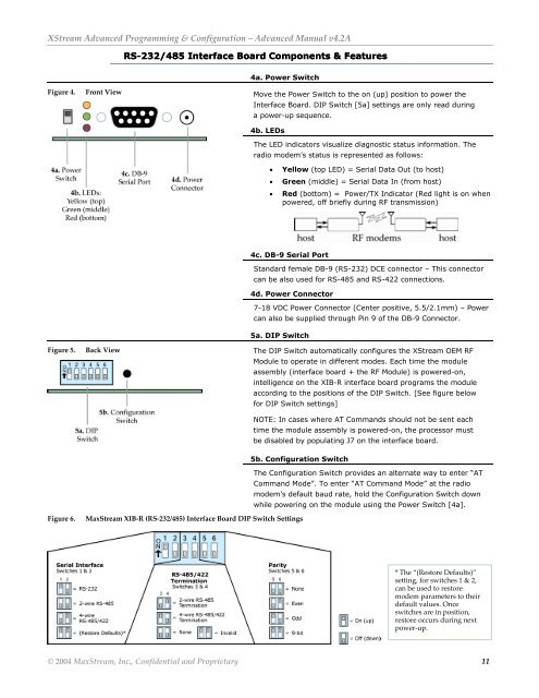
RS-232/485 Interface Board Components & Features<br />
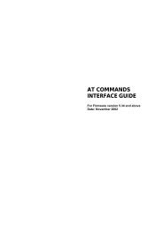
4a. Power Switch<br />
Figure 4. Front View Move the Power Switch to the on (up) position to power the<br />
Interface Board. DIP Switch [5a] settings are only read during<br />
a power-up sequence.<br />
4b. LEDs<br />
The LED indicators visualize diagnostic status information. The<br />
radio modem’s status is represented as follows:<br />
• Yellow (top LED) = Serial Data Out (to host)<br />
• Green (middle) = Serial Data In (from host)<br />
• Red (bottom) = Power/TX Indicator (Red light is on when<br />
powered, off briefly during RF transmission)<br />
4c. DB-9 Serial Port<br />
Standard female DB-9 (RS-232) DCE connector – This connector<br />
can be also used for RS-485 and RS-422 connections.<br />
4d. Power Connector<br />
7-18 VDC Power Connector (Center positive, 5.5/2.1mm) – Power<br />
can also be supplied through Pin 9 of the DB-9 Connector.<br />
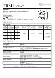
5a. DIP Switch<br />
Figure 5. Back View The DIP Switch automatically configures the XStream OEM RF<br />
Module to operate in different modes. Each time the module<br />
assembly (interface board + the RF Module) is powered-on,<br />
intelligence on the XIB-R interface board programs the module<br />
according to the positions of the DIP Switch. [See figure below<br />
for DIP Switch settings]<br />
NOTE: In cases where AT Commands should not be sent each<br />
time the module assembly is powered-on, the processor must<br />
be disabled by populating J7 on the interface board.<br />
5b. <strong>Configuration</strong> Switch<br />
The <strong>Configuration</strong> Switch provides an alternate way to enter “AT<br />
Command Mode”. To enter “AT Command Mode” at the radio<br />
modem’s default baud rate, hold the <strong>Configuration</strong> Switch down<br />
while powering on the module using the Power Switch [4a].<br />
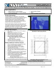
Figure 6.<br />
MaxStream XIB-R (RS-232/485) Interface Board DIP Switch Settings<br />
* The “(Restore Defaults)”<br />
setting, for switches 1 & 2,<br />
can be used to restore<br />
modem parameters to their<br />
default values. Once<br />
switches are in position,<br />
restore occurs during next<br />
power-up.<br />
© 2004 MaxStream, Inc., Confidential and Proprietary 11