XStream⢠Advanced Programming & Configuration
XStream⢠Advanced Programming & Configuration
XStream⢠Advanced Programming & Configuration

Create successful ePaper yourself
Turn your PDF publications into a flip-book with our unique Google optimized e-Paper software.
XStream <strong>Advanced</strong> <strong>Programming</strong> & <strong>Configuration</strong> – <strong>Advanced</strong> Manual v4.2A<br />
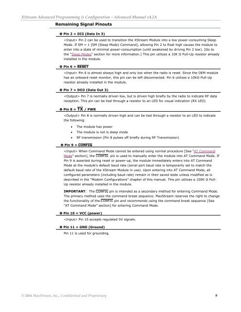
Remaining Signal Pinouts<br />
Pin 2 = DI3 (Data In 3)<br />
Pin 2 can be used to transition the XStream Module into a low power-consuming Sleep<br />
Mode. If SM = 1 [SM (Sleep Mode) Command], allowing Pin 2 to float high causes the module to<br />
enter into a state of minimal power-consumption (until awakened by driving Pin 2 low). [Go to<br />
the “Sleep Modes” section for more information.] This pin utilizes a 10K Ω Pull-Up resistor already<br />
installed in the module.<br />
Pin 6 =<br />
Pin 6 is almost always high and only low when the radio is reset. Since the OEM module<br />
has an onboard reset monitor, this pin can be left disconnected. Pin 6 utilizes a 10KΩ Pull-Up<br />
resistor already installed in the module.<br />
Pin 7 = DO3 (Data Out 3)<br />
Pin 7 is normally driven low, but is driven high briefly by the radio to indicate RF data<br />
reception. This pin can be tied through a resistor to an LED for visual indication (RX LED).<br />
Pin 8 =<br />
/ PWR<br />
Pin 8 is normally driven high and can be tied through a resistor to an LED to indicate<br />
the following:<br />
• The module has power<br />
• The module is not is sleep mode<br />
• RF transmission (Pin 8 pulses off briefly during RF Transmission)<br />
Pin 9 =<br />
When Command Mode cannot be entered using normal procedure [See “AT Command<br />
Mode” section], the pin is used to manually enter the module into AT Command Mode. If<br />
Pin 9 is asserted during reset or power-up, the module immediately enters into AT Command<br />
Mode at the module’s default baud rate (serial port baud rate is temporarily set to match the<br />
default baud rate of the XStream Module in use). Upon entering into AT Command Mode, all<br />
configured parameters (including baud rate) remain in their saved state unless modified as is<br />
described in the “Modem <strong>Configuration</strong>s” chapter of this manual. This pin utilizes a 100K Ω Pull-<br />
Up resistor already installed in the module.<br />
IMPORTANT: The pin is intended as a secondary method for entering Command Mode.<br />
The primary method uses the command break sequence. MaxStream reserves the right to change<br />
the functionality of the pin and recommends using the command break sequence [See<br />
“AT Command Mode” section] for entering Command Mode.<br />
Pin 10 = VCC (power)<br />
Pin 10 accepts regulated 5V signals.<br />
Pin 11 = GND (Ground)<br />
Pin 11 is used for grounding.<br />
© 2004 MaxStream, Inc., Confidential and Proprietary 9