XStream⢠Advanced Programming & Configuration
XStream⢠Advanced Programming & Configuration
XStream⢠Advanced Programming & Configuration
You also want an ePaper? Increase the reach of your titles
YUMPU automatically turns print PDFs into web optimized ePapers that Google loves.
XStream <strong>Advanced</strong> <strong>Programming</strong> & <strong>Configuration</strong> – <strong>Advanced</strong> Manual v4.2A<br />
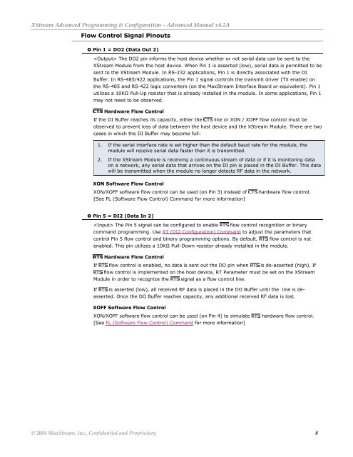
Flow Control Signal Pinouts<br />
Pin 1 = DO2 (Data Out 2)<br />
The DO2 pin informs the host device whether or not serial data can be sent to the<br />
XStream Module from the host device. When Pin 1 is asserted (low), serial data is permitted to be<br />
sent to the XStream Module. In RS-232 applications, Pin 1 is directly associated with the DI<br />
Buffer. In RS-485/422 applications, the Pin 1 signal controls the transmit driver (TX enable) on<br />
the RS-485 and RS-422 logic converters (on the MaxStream Interface Board or equivalent). Pin 1<br />
utilizes a 10KΩ Pull-Up resistor that is already installed in the module. In some applications, Pin 1<br />
may not need to be observed.<br />
Hardware Flow Control<br />
If the DI Buffer reaches its capacity, either the<br />
line or XON / XOFF flow control must be<br />
observed to prevent loss of data between the host device and the XStream Module. There are two<br />
cases in which the DI Buffer may become full:<br />
1. If the serial interface rate is set higher than the default baud rate for the module, the<br />
module will receive serial data faster than it is transmitted.<br />
2. If the XStream Module is receiving a continuous stream of data or if it is monitoring data<br />
on a network, any serial data that arrives on the DI pin is placed in the DI Buffer. This data<br />
will be transmitted when the module no longer detects RF data in the network.<br />
XON Software Flow Control<br />
XON/XOFF software flow control can be used (on Pin 3) instead of<br />
[See FL (Software Flow Control) Command for more information]<br />
hardware flow control.<br />
Pin 5 = DI2 (Data In 2)<br />
The Pin 5 signal can be configured to enable flow control recognition or binary<br />
command programming. Use RT (DI2 <strong>Configuration</strong>) Command to adjust the parameters that<br />
control Pin 5 flow control and binary programming options. By default, flow control is not<br />
enabled. This pin utilizes a 10KΩ Pull-Down resistor already installed in the module.<br />
Hardware Flow Control<br />
If flow control is enabled, no data is sent out the DO pin when is de-asserted (high). If<br />
flow control is implemented on the host device, RT Parameter must be set on the XStream<br />
Module in order to recognize the signal as a flow control line.<br />
If is asserted (low), all received RF data is placed in the DO Buffer until the line is deasserted.<br />
Once the DO Buffer reaches capacity, any additional received RF data is lost.<br />
XOFF Software Flow Control<br />
XON/XOFF software flow control can be used (on Pin 4) to simulate<br />
[See FL (Software Flow Control) Command for more information]<br />
hardware flow control.<br />
© 2004 MaxStream, Inc., Confidential and Proprietary 8


