Book template - KISSsoft AG
Book template - KISSsoft AG
Book template - KISSsoft AG

You also want an ePaper? Increase the reach of your titles
YUMPU automatically turns print PDFs into web optimized ePapers that Google loves.
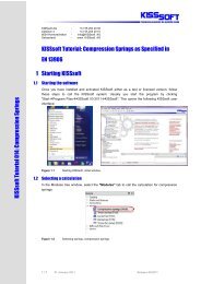
Chapter 1 I-20 Description of the calculation modules<br />
2.9 K05m Inventor interface<br />
The interface between Inventor and <strong>KISSsoft</strong> is achieved by direct integration in<br />
the 3D CAD system. Use this to start all <strong>KISSsoft</strong> calculation modules directly<br />
from within Inventor. Face or bevel gears calculated in <strong>KISSsoft</strong> can be generated<br />
directly in Inventor as a 3D part with a real tooth form. From <strong>KISSsoft</strong>, in the tooth<br />
form calculation module, you simply press a button to start Inventor. This opens a<br />
new part and generates the appropriate part. You can create spur or helical cylindrical<br />
gears, which are external or internal, or straight-toothed bevel gears, as defined<br />
in DIN 3971, Figure 1. Furthermore, you have the option of adding toothing<br />
to existing shafts. If you insert a reference layer to a side face of an existing shaft<br />
and then select it, the tooth form is cut out there on the shaft blank. In the 2D area,<br />
the interface also gives you the option of adding gear manufacturing data automatically<br />
as a text field on thedrawing. The gear manufacturing data is attached to the<br />
relevant cutout (tooth space).<br />
2.10 K05n NX interface<br />
The interface between NX and <strong>KISSsoft</strong> is achieved by direct integration in the 3D<br />
CAD system. Use this to start all <strong>KISSsoft</strong> calculation modules directly from within<br />
NX. Cylindrical or bevel gears calculated in <strong>KISSsoft</strong> can be generated directly<br />
in NX as a 3D part with a real tooth form. You can create spur or helical cylindrical<br />
gears with straight or sloping teeth, which are external or internal. Furthermore,<br />
you have the option of adding toothing to existing shafts. If you insert a reference<br />
layer to a side face of an existing shaft and then select it, the tooth form is cut out<br />
there on the shaft blank. In the 2D area, the interface also gives you the option of<br />
adding gear manufacturing data automatically as a text field on the drawing. The<br />
gear manufacturing data is attached to the relevant cutout (tooth space).<br />
2.11 K05o* CATIA interface<br />
Cylindrical or bevel gears calculated in <strong>KISSsoft</strong> can be generated directly in CAT-<br />
IA V5 as a 3D part with a real tooth form. You must open CATIA V5 before you<br />
start a 3D generation in <strong>KISSsoft</strong>. In CATIA V5, this then opens a new part and the<br />
appropriate part is generated. You can create spur or helical cylindrical gears,<br />
which are external or internal. In the 2D area, the interface also gives you the option<br />
of adding gear manufacturing data automatically as a text field on the drawing.<br />
2.12 K05p* CoCreate interface<br />
Cylindrical or bevel gears calculated in <strong>KISSsoft</strong> can be generated directly in<br />
CoCreate Modeling as a 3D part with a real tooth form. From <strong>KISSsoft</strong>, in the<br />
tooth form calculation module, simply press a button to start CoCreate. This opens<br />
a new part and generates the appropriate part. You can create spur or helical cylindrical<br />
gears, which are external or internal, or straight-toothed bevel gears, as defined<br />
in DIN 3971, Figure 1.