Book template - KISSsoft AG
Book template - KISSsoft AG
Book template - KISSsoft AG

Create successful ePaper yourself
Turn your PDF publications into a flip-book with our unique Google optimized e-Paper software.
aa<br />
KISSSOFT<br />
RELEASE 03/2011<br />
PRODUCT<br />
DESCRIPTION
Issue 1.3<br />
Copyright Notice:<br />
© 2011 <strong>KISSsoft</strong> <strong>AG</strong><br />
Uetzikon 4<br />
CH-8634 Hombrechtikon Switzerland<br />
All rights retained<br />
This documentation may not be copied without the express written approval of <strong>KISSsoft</strong> <strong>AG</strong>.
Inhalt<br />
Table of Contents<br />
I Description of the calculation module I-12<br />
1 Hardware a nd softwar e requiremen ts ........................................... I -13<br />
1.1 Program versions ........................................................................................ I-13<br />
1.2 Computer configuration ............................................................................... I-15<br />
2 Base K modu les ................................................................................. I -16<br />
2.1 K1 base module .......................................................................................... I-16<br />
2.2 K02 output text and interface ...................................................................... I-17<br />
2.3 K05 CAD interfaces ................................................................................... I-18<br />
2.4 K05a DXF interfaces .................................................................................. I-18<br />
2.5 K05e IGES interface ................................................................................... I-18<br />
2.6 K05d SolidEdge interface ........................................................................... I-18<br />
2.7 K05g Neutral format interface .................................................................... I-19<br />
2.8 K05k SolidWorks interface ........................................................................ I-19<br />
2.9 K05m Inventor interface ............................................................................. I-20<br />
2.10 K05n NX interface ...................................................................................... I-20<br />
2.11 K05o* CATIA interface ............................................................................. I-20<br />
2.12 K05p* CoCreate interface .......................................................................... I-20<br />
2.13 K05q* ProEngineer interface ...................................................................... I-21<br />
2.14 K05r* Think3 interface ............................................................................... I-21<br />
2.15 K05s Parasolid display window .................................................................. I-21<br />
2.16 K05u Export STEP format (parasolid) ....................................................... I-21<br />
2.17 P01 Parasolid base module .......................................................................... I-21<br />
2.18 P02 Generate a helical toothed cylindrical gear (parasolid) ....................... I-21<br />
2.19 P03 Generate a bevel gear (parasolid) ........................................................ I-21<br />
2.20 P03a Generate a straight-toothed bevel gear (parasolid) ............................ I-22<br />
2.21 P04 Generate face gear (parasolid) ............................................................. I-22<br />
2.22 P05 Generate a globoid worm gear (parasolid) .......................................... I-22<br />
2.23 K07 user database (materials etc.) .............................................................. I-22
Inhalt<br />
2.24 K7a material management (always present) ............................................... I-22<br />
2.25 K7b Smith-Haigh diagram .......................................................................... I-22<br />
2.26 K09 Hardness Conversion (in the Extras menu) ......................................... I-23<br />
2.27 K10 Calculating tolerances ......................................................................... I-23<br />
2.28 K12 Strength analysis with local stresses (FKM guideline) ....................... I-23<br />
2.29 K14 Hertzian pressure ................................................................................. I-24<br />
2.30 K15 Linear Drive ......................................................................................... I-25<br />
3 S hafts, axe s, be aring - W-modu le ................................................... I -26<br />
3.1 General ........................................................................................................ I-26<br />
3.2 W01 Shafts base module ............................................................................ I-28<br />
3.3 W01a Input data for several shafts ............................................................. I-29<br />
3.4 W01b Bearing offset, Bearing clearance .................................................... I-29<br />
3.5 W01c Take into account contact angle ....................................................... I-29<br />
3.6 W01s Load spectra ..................................................................................... I-30<br />
3.7 W03 Calculate bending and bearing forces ................................................ I-30<br />
3.8 W03a take into account deformation due to shearing ................................. I-31<br />
3.9 W03b Non-linear shaft ............................................................................... I-31<br />
3.10 W03c Heat expansion ................................................................................. I-31<br />
3.11 W03d non-linear stiffness ........................................................................... I-31<br />
3.12 W04 calculation of the critical speeds ........................................................ I-31<br />
3.13 W04x gyro effect ........................................................................................ I-32<br />
3.14 W05 cylindrical roller bearing and roller bearing service life .................... I-32<br />
3.15 W05a Bearing load spectra ......................................................................... I-33<br />
3.16 W05b reference service life as specified in ISO/TS 16281 ........................ I-33<br />
3.17 W05c Load distribution in the bearing ....................................................... I-34<br />
3.18 W06 Calculate the service life and static calculation of cross-sections ...... I-35<br />
3.19 W06a calculation method Hänchen + Decker ........................................... I-36<br />
3.20 W06b calculation method DIN 743 ............................................................ I-36<br />
3.21 W06c Calculation methods according to the FKM Guideline .................... I-36<br />
3.22 W06s Strength calculation with load spectra .............................................. I-36<br />
3.23 W07 Hydro-dynamic radial journal bearings ............................................. I-37<br />
3.24 W07a calculation in accordance with Niemann .......................................... I-37
Inhalt<br />
3.25 W07b calculation according to DIN 31652 ................................................ I-37<br />
3.26 W08 Grease lubricated radial journal bearings ........................................... I-37<br />
3.27 W07c Hydrodynamic axial journal bearing ................................................ I-37<br />
3.28 W10 Tooth trace correction ........................................................................ I-38<br />
3.29 W12 Shaft arrangement (integrated design tool) ........................................ I-38<br />
3.30 W13 Buckling .............................................................................................. I-40<br />
4 Mac hin e e lemen ts - M module ........................................................ I-41<br />
4.1 M01a Cylindrical interference fit ............................................................... I-41<br />
4.2 M01b Conical interference fit ..................................................................... I-41<br />
4.3 M01x Additional function for a press fit .................................................... I-41<br />
4.4 M01c clamped connections ......................................................................... I-43<br />
4.5 M02a Key / Key way .................................................................................. I-43<br />
4.6 M02b Straight-sided spline/ Multi-groove profile ...................................... I-44<br />
4.7 M02c Spline ................................................................................................ I-44<br />
4.8 M02d Polygon ............................................................................................ I-45<br />
4.9 M02e Woodruff key ................................................................................... I-45<br />
4.10 M03a Pin calculation .................................................................................. I-46<br />
4.11 M04 Bolt calculation .................................................................................. I-46<br />
4.12 M04a Eccentric clamping and load, configurations (for M04) ................... I-46<br />
4.13 M04b Bolt calculation at high and low temperatures (for M04) ................ I-47<br />
4.14 M08 Welded joints ..................................................................................... I-47<br />
4.15 M09a Glued and Soldered Joints ................................................................. I-49<br />
5 S p rings - F-m odule ............................................................................ I -51<br />
5.1 F01 compression springs calculation .......................................................... I-51<br />
5.2 F02 tension spring calculation .................................................................... I-51<br />
5.3 F03 Leg spring calculation ......................................................................... I-51<br />
5.4 F04 disk spring calculation ......................................................................... I-51<br />
5.5 F05 torsion bar spring calculation ............................................................... I-52<br />
6 G ears - Z-modul es .............................................................................. I -53<br />
6.1 Z01 Gear - Base module ............................................................................. I-53
Inhalt<br />
6.2 Z01x extension of cylindrical gear geometry ............................................. I-54<br />
6.3 Z19h Sizing of deep toothing ..................................................................... I-55<br />
6.4 Z15 Calculate the details used to modify the profile of cylindrical gears .. I-56<br />
6.5 Z19a Calculation with operating center distance and profile shift according to<br />
manufacture ......................................................................................................... I-56<br />
6.6 Z19d Optimize axis centre distance with respect to balanced sliding ........ I-56<br />
6.7 Z19e Representation of specific sliding ...................................................... I-56<br />
6.8 Z19f suggestion of sensible lead corrections .............................................. I-57<br />
6.9 Z19l Conversion of profile shift coefficient and tooth thickness deviation I-57<br />
6.10 Z19n Profile and tooth trace diagrams }...................................................... I-57<br />
6.11 Z02 Strength calculation as specified in DIN 3990 .................................... I-57<br />
6.12 Z02a Strength calculation as specified in ISO 6336 ................................... I-58<br />
6.13 Z02x Static strength of the tooth root ......................................................... I-59<br />
6.14 Z13 Calculation using the <strong>AG</strong>MA standard (USA standard) ..................... I-59<br />
6.15 Z13b Calculation in accordance with <strong>AG</strong>MA 6011/<strong>AG</strong>MA 6014 (US norm) I-<br />
60<br />
6.16 Z02b Strength calculation as specified in BV RINA .................................. I-60<br />
6.17 Z10 Cylindrical gear calculation using the FVA method ........................... I-60<br />
6.18 Z14 Plastic gears ......................................................................................... I-60<br />
6.19 Z19i Tooth form factor calculation using the graphical method ................ I-61<br />
6.20 Z19m Flash temperature progression ......................................................... I-62<br />
6.21 Z01a Planets, 3 and 4 gear .......................................................................... I-62<br />
6.22 Z19g Calculate the center points of planets or idler gears .......................... I-64<br />
6.23 Z01b Rack ................................................................................................... I-64<br />
6.24 Z03 Cylindrical gear-Rough sizing ............................................................. I-64<br />
6.25 Z04 Cylindrical gear-Fine sizing ................................................................ I-65<br />
6.26 Z04a Additional strength calculation of all variants ................................... I-66<br />
6.27 Z05 Tooth form calculation and display ..................................................... I-67<br />
6.28 Z05x Animate the 2D display ..................................................................... I-68<br />
6.29 Z05a Input any tool or tooth form .............................................................. I-69<br />
6.30 Z05c Reference profile calculation for gears with involutes or special profiles<br />
I-69
Inhalt<br />
6.31 Z05d Calculate the tooth form from the paired gear (generate with other gear<br />
in the pair) ........................................................................................................... I-69<br />
6.32 Z05e Addition for mold making ................................................................. I-70<br />
6.33 Z05f Arc shaped tip relief ........................................................................... I-70<br />
6.34 Z05g Optimum tooth root rounding ............................................................ I-71<br />
6.35 Z05h Cycloid and circular arc toothings ...................................................... I-72<br />
6.36 Z05i Circular arcs approximation ............................................................... I-72<br />
6.37 Z05j Display collisions in the meshing (cylindrical gears) ........................ I-72<br />
6.38 Z05k Display collisions in the meshing (worms/spiral-toothed gears) ....... I-73<br />
6.39 Z05l Using the same tool multiple times .................................................... I-73<br />
6.40 Z05m Non-symmetrical gears .................................................................... I-73<br />
6.41 Z05n Straight line flank .............................................................................. I-73<br />
6.42 Z19k Lubrication gap EHD/ Scoring .......................................................... I-74<br />
6.43 Z23 Calculate the tooth root load capacity of internal gears with the influence<br />
of the ring gear in accordance with VDI 2737 and calculate the deformation of gear<br />
rings .................................................................................................................... I-74<br />
6.44 Z24 Meshing stiffness of the gear pair and transmission error ................... I-75<br />
6.45 Z25 Graphical representation of Hertzian flattening and tooth root strain along<br />
the actual tooth form ........................................................................................... I-75<br />
6.46 Z26 Displacement volumes for gear pumps ............................................... I-76<br />
6.47 Z26a Additional option for gear pumps Z26 .............................................. I-76<br />
6.48 Z27 Kinematics based on the actual tooth form ......................................... I-77<br />
6.49 Z29 Layout and checking of master gears .................................................. I-77<br />
6.50 Z30 Micropitting (frosting) and flash temperature ...................................... I-78<br />
6.51 Z31 Wear .................................................................................................... I-78<br />
6.52 Z32 Calculation of contact analysis under load .......................................... I-79<br />
6.53 Z33 Profile correction optimization with contact analysis under load ....... I-80<br />
6.54 Z06 Face gear calculation (Z060) ............................................................... I-80<br />
6.55 Z06a Strength calculation based on ISO 6336/ Literature .......................... I-81<br />
6.56 Z06b Strength calculation based on CrownGear/ DIN 3990 ...................... I-81<br />
6.57 Z06c Strength calculation based on ISO 10300, method B ........................ I-81<br />
6.58 Z06d Strength calculation based on DIN 3991, method B ......................... I-82<br />
6.59 Z6e Static strength ....................................................................................... I-82
Inhalt<br />
6.60 Z6f 3-D display ............................................................................................ I-82<br />
6.61 Z07 Bevel gear calculation (Z070) ............................................................. I-82<br />
6.62 Z07d Gleason bevel gear toothing .............................................................. I-83<br />
6.63 Z07e Strength calculation based on ISO 10300, methods B and C ............ I-83<br />
6.64 Z07g Strength calculation based on DIN 3991 ........................................... I-84<br />
6.65 Z07h Strength calculation for plastics ........................................................ I-84<br />
6.66 Z07i Calculation of bevel gear differentials ............................................... I-84<br />
6.67 Z07j Strength calculation based on <strong>AG</strong>MA 2003 ...................................... I-84<br />
6.68 Z07a bevel gears with cyclo-palloid and palloid-intermeshing .................. I-84<br />
6.69 Z07b Hypoid gears with cyclo-palloid gear teeth ....................................... I-85<br />
6.70 Z07p 3-D display ......................................................................................... I-87<br />
6.71 Z08 Worm gear calculation (Z080) ............................................................ I-87<br />
6.72 Z08a Strength calculation based on DIN 3996 ........................................... I-87<br />
6.73 Z08b Strength calculation based on ISO 14521 ......................................... I-88<br />
6.74 Z08c Strength calculation based on <strong>AG</strong>MA 6034 and <strong>AG</strong>MA 6135 ......... I-88<br />
6.75 Z08p 3-D display ......................................................................................... I-89<br />
6.76 Z19b Worm calculation with sizing using the normal module (tool module) I-<br />
89<br />
6.77 Z17 Calculate spiral-toothed gear pairs ...................................................... I-89<br />
6.78 Z17a Strength calculation in accordance with ISO 6336/Hirn ................... I-89<br />
6.79 Z17b Strength calculation in accordance with Niemann/VDI 2545 ........... I-90<br />
6.80 Z17c Strength calculation in accordance with Hoechst ............................... I-91<br />
6.81 Z09 Splines ................................................................................................. I-91<br />
6.82 Z12 Operating backlash .............................................................................. I-92<br />
6.83 Z22 Hardening depth .................................................................................. I-92<br />
6.84 Z16 Torque sizing ....................................................................................... I-92<br />
6.85 Z16a Torque sizing for load spectra ........................................................... I-93<br />
6.86 Z18 Service life calculation ........................................................................ I-93<br />
6.87 Z18a Calculate service life for load spectra ................................................ I-93<br />
6.88 Z40 non-circular gears ................................................................................. I-95<br />
7 Belt/c hai n dr ive s Z mo dule ............................................................. I -97<br />
7.1 Z90 V-belts (Z090) ..................................................................................... I-97
Inhalt<br />
7.2 Z91 Toothed belts (Z091) ........................................................................... I-97<br />
7.3 Z92 Chain gears (Z092) ............................................................................... I-99<br />
8 A utomot ive - A Modu le .................................................................... I -100<br />
8.1 A10 Synchronization (A010) ..................................................................... I-101<br />
9 KI S S sys - K11 -Modu le ...................................................................... I -102<br />
9.1 Overview ................................................................................................... I-102<br />
9.2 Modules .................................................................................................... I-102<br />
9.3 Different views of the data ........................................................................ I-102<br />
9.4 Modeling ................................................................................................... I-102<br />
9.5 Variants ..................................................................................................... I-103<br />
9.6 Example applications ................................................................................. I-104<br />
II Index<br />
II-105
I Descri pti on of th e c alcu lation mo dul e<br />
Chapter 1 I-12 Description of the calculation modules<br />
Chapter 1<br />
Description of the calculation<br />
modules<br />
Description of characters<br />
* Programs from other manufacturers. We provide support and implement a<br />
compatible installation.<br />
K02a Short designation of the calculation module. You will also find this abbreviation<br />
in the pricelist.<br />
(M02a) Module designation as used in the software
Chapter 1 I-13 Description of the calculation modules<br />
1 Hardware and software requirements<br />
1.1 Program versions<br />
Demo program: All the program modules can be tested in a demonstration<br />
program. The scope of the demo version is the same as the full version, apart<br />
from a few restrictions (listed below):<br />
<br />
<br />
<br />
<br />
<br />
You cannot save calculation files and results<br />
You can only select the first item in the lists<br />
You cannot export graphics (DXF, CDL, IGES, etc.)<br />
The text "<strong>KISSsoft</strong> demo version" also appears in the graphics<br />
A demo window appears before each actual calculation<br />
The reports have a demo extension<br />
Programs from other suppliers which we also provide are not included in the demo<br />
version. The demo program gives you a good insight into how to work with the<br />
<strong>KISSsoft</strong> system.<br />
Test installation: Furthermore, starting on a date which you specify, you can<br />
also test a full version of our programs for a period of 30 days. You will then<br />
have unrestricted access to all our currently available calculation modules. The<br />
test installation gives you the opportunity to test our programs in a practical<br />
environment.<br />
Single user version: Copying protection: For security reasons, the programs<br />
can be copied at any time. To limit the illegal distribution of these programs, a<br />
software USB port protection device "dongle" is supplied along with the single<br />
user version. This is then inserted into the computer's USB port. Alternatively,<br />
on request, we can also supply an LPT protection device, however this is not<br />
supported by 64-bit operating systems.<br />
Multi-user network installation with access directory: We can supply a<br />
network installation, in which any number of users can work with the software,<br />
but at the same time only a limited number (depending on the number specified<br />
on the license) of users have authorization. This makes <strong>KISSsoft</strong> extremely<br />
flexible and easy to integrate into any network structure. To manage these licenses,<br />
you only need to install one directory with full rights on a server with<br />
general access rights for <strong>KISSsoft</strong> users. This does not start any server processes<br />
or similar processes. The license file contains the path of the access directory<br />
and the logical serial number of the network drive.
Chapter 1 I-14 Description of the calculation modules<br />
Multi-user network installation with USB protection: Alternatively, you can<br />
also run the network installation with USB protection on the server. To achieve<br />
this, you need a server with a Windows operating system and a USB port as<br />
well as a directory to which both the server and clients have read and write access.
Chapter 1 I-15 Description of the calculation modules<br />
1.2 Computer configuration<br />
To run the programs, you require the following computer configuration:<br />
Operating system: Windows XP (32bit/64bit), Windows VISTA (32bit/64bit)<br />
or Windows 7 (32bit/64bit)<br />
RAM: at least 500 MB RAM<br />
Screen resolution: at least 1024 x 768 pixels<br />
Printer: Windows printer<br />
Memory: hard disk approximately 500 MB (depending on requirements)
Chapter 1 I-16 Description of the calculation modules<br />
2 Base K modules<br />
2.1 K1 base module<br />
This module represents the administration module which is the basis for all calculation<br />
modules. The following items are covered:<br />
<strong>KISSsoft</strong> in different languages: <strong>KISSsoft</strong> is available in five languages. You<br />
can switch language separately for calculation reports and the user interface<br />
whilst the program is running (see also K02)<br />
Data storage: The <strong>KISSsoft</strong> system stores the data input by users and the results<br />
of calculations in a freely-definable storage medium (diskette, local hard<br />
disk, network server). You can create project-specific directories in the framework<br />
of project management.<br />
Recording the results: You can select where the results are output (printer or<br />
file) and how they are displayed to suit your own requirements. Additional<br />
properties:<br />
<br />
<br />
<br />
The report file is in RTF format. Although an internal editor is available,<br />
you can also select an external editor. If you use an RTF editor (for example,<br />
KISSedit which is supplied with the system, Workpad or MS Word)<br />
relevant graphics are displayed in the report.<br />
You can also select the scope of the printout (detailed variant and summary,<br />
to 9 levels of detail)<br />
The content and appearance of the report <strong>template</strong>s can easily be modified<br />
using a text editor. Here you can pre-define formatting, such as font size,<br />
bold, italic or underlined.<br />
You can select the language of the printout (see option K02)<br />
<br />
<br />
<br />
Automatic page breaks and numbering.<br />
User-specific print header (for example, to support quality assurance as<br />
specified in ISO 900x)<br />
Display in a report editor. This allows you to add comments quickly and<br />
easily. In the report editor (KISSedit), you can select the header and footer<br />
format. You can include your company logo. The report you generate can<br />
be viewed directly. The report is displayed in a Word processing program,<br />
usually in the editor supplied with the system. You can use the <strong>KISSsoft</strong><br />
settings to pre-define which word processing program you want to use.<br />
Graphical representations and plotter: To help you input and check data, at<br />
some points in the program, the inputs are shown in a scale graphic. Simply<br />
click a button to print out images, store them in graphics formats, or output
Chapter 1 I-17 Description of the calculation modules<br />
them via a CAD interface (DXF, IGES, see modules K05a and K05e). You can<br />
also define your own system of coordinates, line types and colors.<br />
Help function: <strong>KISSsoft</strong> has a powerful help system. Press function key F1 at<br />
any time to request information about the current situation in the program. In<br />
addition, you can call other topics in the help system by selecting them from<br />
the table of contents or by clicking a cross-reference. As you can also display<br />
graphics, consulting the manual is not necessary when working with <strong>KISSsoft</strong>.<br />
Toggling units: In <strong>KISSsoft</strong>, you can toggle units at any time. You can also<br />
store your own tailored configurations alongside the pre-prepared default settings.<br />
Input parameter as formula: In the interface you can perform simple calculations<br />
to help your work, directly when you input the data. This is useful if, for<br />
example, you must calculate a torque from the force and the lever arm, or work<br />
out a length from several masures.<br />
Calculator: You can activate a calculator program at any time, and use it to<br />
perform simple calculations.<br />
Data exchange between different program sections: At different places in<br />
the program you can refer back to the results of data that has already been calculated<br />
in other program modules. As a consequence, you can, for example,<br />
access data from the gear calculation when defining the external forces in the<br />
shaft.<br />
Public data interface: The freely-definable formatting of this data interface<br />
gives you a very effective communications tool for interacting with external<br />
programs. It has been specially designed to allow <strong>KISSsoft</strong> to be integrated into<br />
CAD programs. All input and output data can be exported in ASCII format.<br />
The scope and format of this data is freely definable. To allow this, each calculation<br />
module contains an editable report file. External programs can, in addition,<br />
transfer input data (also in ASCII format) to the calculation modules. These<br />
files are imported automatically during start-up and the data is displayed on<br />
the screen.<br />
Calculation server, <strong>KISSsoft</strong> API: You can use <strong>KISSsoft</strong> as a calculation<br />
server for your own program developments. You can do this either via the public<br />
data interface (see above) or via a COM interface.<br />
2.2 K02 output text and interface<br />
The program is currently available in the following languages:
Chapter 1 I-18 Description of the calculation modules<br />
Authorization K02 German (always included)<br />
Authorization K02a English<br />
Authorization K02b French<br />
Authorization K02c Italian<br />
Authorization K02d Spanish<br />
2.3 K05 CAD interfaces<br />
<strong>KISSsoft</strong>'s public interface is a powerful tool designed to create CAD integrations.<br />
The modular structure of <strong>KISSsoft</strong> programs enables them to be integrated smoothly<br />
into individual calculation functions in CAD. Detailed instructions about how to<br />
create interfaces on the CAD side are available in the manual.<br />
Integration of <strong>KISSsoft</strong>:<br />
In addition to this general solution, the system also has a wide range of standard<br />
formats for graphical displays. You can also request CAD integrations for numerous<br />
other CAD systems.<br />
2.4 K05a DXF interfaces<br />
All two-dimensional graphical data is described in AutoCAD DXF data format. As<br />
this interface is used in many CAD systems, this option can therefore also be used<br />
for other CAD systems. If necessary, you can also specify the layer in the inputs<br />
and outputs.<br />
2.5 K05e IGES interface<br />
Outputs all two dimensional graphical data in IGES format.<br />
2.6 K05d SolidEdge interface<br />
The interface between Solid Edge and <strong>KISSsoft</strong> is achieved by direct integration in<br />
the 3D CAD system. This enables you to start all <strong>KISSsoft</strong> calculation modules<br />
directly from Solid Edge. Cylindrical or bevel gears calculated in <strong>KISSsoft</strong> can be<br />
generated directly in Solid Edge as a 3D part with a real tooth form. From the<br />
<strong>KISSsoft</strong> system, in the tooth form calculation module, simply press a button to<br />
start Solid Edge. This opens a new part and generates the appropriate part. You can<br />
create cylindrical gears with straight or helical teeth, which are external or internal,<br />
or straight-toothed bevel gears, as defined in DIN 3971, Figure 1. Furthermore, you<br />
have the option of adding toothing to existing shafts. If you insert a reference layer<br />
to a side face of an existing shaft and then select it, the tooth form is cut out there<br />
on the shaft blank. In the 2D area, the interface also allows you to add gear manu-
Chapter 1 I-19 Description of the calculation modules<br />
facturer data automatically as a text field on the drawing. The gear manufacturing<br />
data is attached to the relevant cutout (tooth space).<br />
2.7 K05g Neutral format interface<br />
Output the three dimensional gear model in 3D view in IGES, STEP or SAT format.<br />
This covers cylindrical gears, straight or helical bevel gears in form 1 (tip, part<br />
and root cone peak at one point) spiral-toothed gears and worms.<br />
2.8 K05k SolidWorks interface<br />
The interface between Solid Works and <strong>KISSsoft</strong> is achieved by direct integration<br />
in the 3D CAD system. Use this to start all <strong>KISSsoft</strong> calculation modules directly<br />
from within Solid Works. Cylindrical or bevel gears calculated in <strong>KISSsoft</strong> can be<br />
generated directly in SolidWorks as a 3D part with real tooth form. From <strong>KISSsoft</strong>,<br />
in the tooth form calculation module, simply press a button to start Solid Works.<br />
This opens a new part and generates the appropriate part. You can create spur or<br />
helical cylindrical gears, which are external or internal, or straight-toothed bevel<br />
gears, as defined in DIN 3971, Figure 1. Furthermore, you have the option of adding<br />
toothing to existing shafts. If you insert a reference layer to a side face of an<br />
existing shaft and then select it, the tooth form is cut out there on the shaft blank. In<br />
the 2D area, the interface also gives you the option of adding gear manufacturing<br />
data automatically as a text field on the drawing. The gear manufacturing data is<br />
attached to the relevant cutout (tooth space).<br />
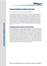
Figure 1.1: Pinion shaft generated in <strong>KISSsoft</strong>
Chapter 1 I-20 Description of the calculation modules<br />
2.9 K05m Inventor interface<br />
The interface between Inventor and <strong>KISSsoft</strong> is achieved by direct integration in<br />
the 3D CAD system. Use this to start all <strong>KISSsoft</strong> calculation modules directly<br />
from within Inventor. Face or bevel gears calculated in <strong>KISSsoft</strong> can be generated<br />
directly in Inventor as a 3D part with a real tooth form. From <strong>KISSsoft</strong>, in the tooth<br />
form calculation module, you simply press a button to start Inventor. This opens a<br />
new part and generates the appropriate part. You can create spur or helical cylindrical<br />
gears, which are external or internal, or straight-toothed bevel gears, as defined<br />
in DIN 3971, Figure 1. Furthermore, you have the option of adding toothing<br />
to existing shafts. If you insert a reference layer to a side face of an existing shaft<br />
and then select it, the tooth form is cut out there on the shaft blank. In the 2D area,<br />
the interface also gives you the option of adding gear manufacturing data automatically<br />
as a text field on thedrawing. The gear manufacturing data is attached to the<br />
relevant cutout (tooth space).<br />
2.10 K05n NX interface<br />
The interface between NX and <strong>KISSsoft</strong> is achieved by direct integration in the 3D<br />
CAD system. Use this to start all <strong>KISSsoft</strong> calculation modules directly from within<br />
NX. Cylindrical or bevel gears calculated in <strong>KISSsoft</strong> can be generated directly<br />
in NX as a 3D part with a real tooth form. You can create spur or helical cylindrical<br />
gears with straight or sloping teeth, which are external or internal. Furthermore,<br />
you have the option of adding toothing to existing shafts. If you insert a reference<br />
layer to a side face of an existing shaft and then select it, the tooth form is cut out<br />
there on the shaft blank. In the 2D area, the interface also gives you the option of<br />
adding gear manufacturing data automatically as a text field on the drawing. The<br />
gear manufacturing data is attached to the relevant cutout (tooth space).<br />
2.11 K05o* CATIA interface<br />
Cylindrical or bevel gears calculated in <strong>KISSsoft</strong> can be generated directly in CAT-<br />
IA V5 as a 3D part with a real tooth form. You must open CATIA V5 before you<br />
start a 3D generation in <strong>KISSsoft</strong>. In CATIA V5, this then opens a new part and the<br />
appropriate part is generated. You can create spur or helical cylindrical gears,<br />
which are external or internal. In the 2D area, the interface also gives you the option<br />
of adding gear manufacturing data automatically as a text field on the drawing.<br />
2.12 K05p* CoCreate interface<br />
Cylindrical or bevel gears calculated in <strong>KISSsoft</strong> can be generated directly in<br />
CoCreate Modeling as a 3D part with a real tooth form. From <strong>KISSsoft</strong>, in the<br />
tooth form calculation module, simply press a button to start CoCreate. This opens<br />
a new part and generates the appropriate part. You can create spur or helical cylindrical<br />
gears, which are external or internal, or straight-toothed bevel gears, as defined<br />
in DIN 3971, Figure 1.
Chapter 1 I-21 Description of the calculation modules<br />
2.13 K05q* ProEngineer interface<br />
Cylindrical or bevel gears calculated in <strong>KISSsoft</strong> can be generated directly in Pro-<br />
Engineer as a 3D part with a real tooth form. You must open ProEngineer before<br />
you start a 3D generation in <strong>KISSsoft</strong>. In ProEngineer this then opens a new part<br />
and the appropriate part is generated. You can create spur or helical cylindrical<br />
gears, which are external or internal, or straight-toothed bevel gears, as defined in<br />
DIN 3971, Figure 1. In the 2D area, the interface also gives you the option of adding<br />
gear manufacturing data automatically as a text field on the drawing.<br />
2.14 K05r* Think3 interface<br />
Cylindrical or bevel gears calculated in <strong>KISSsoft</strong> can be generated directly in<br />
Think3 as a 3D part with a real tooth form. You must open Think 3 before you start<br />
a 3D generation in <strong>KISSsoft</strong>. In Think3 this then opens a new part and the appropriate<br />
part is generated. You can create spur or helical cylindrical gears, which are<br />
external or internal. In the 2D area, the interface also gives you the option of adding<br />
gear manufacturing data automatically as a text field on the drawing.<br />
2.15 K05s Parasolid display win dow<br />
The cylindrical gears, racks, bevel gear, face gears, crossed helical gears and worm<br />
gears calculated in <strong>KISSsoft</strong> can be displayed directly in this parasolid 3D display<br />
window.<br />
2.16 K05u Export STEP format (paras olid)<br />
Export the displayed 3D models in the parasolid display window in STEP format.<br />
2.17 P01 Parasolid base module<br />
This is the base module for generating individual models in parasolid form.<br />
2.18 P02 Generate a helical toothed cylindr i-<br />
cal gear (parasolid)<br />
Prerequisite: authorization P1<br />
This module generates straight and helical toothed cylindrical gears in parasolid<br />
form. These can then be viewed in the 3D parasolid display window.<br />
2.19 P03 Generate a bevel gear (paras olid)<br />
Prerequisite: authorization P1<br />
This module generates straight, angled and spiral toothed bevel gears in parasolid<br />
form. These can then be viewed in the 3D parasolid display window.
Chapter 1 I-22 Description of the calculation modules<br />
2.20 P03a Generate a straight -toothed bevel<br />
gear (parasolid)<br />
Prerequisite: authorization P1<br />
This module generates straight-toothed bevel gears in parasolid form. These can<br />
then be viewed in the 3D parasolid display window.<br />
2.21 P04 Generate face gear (parasolid)<br />
Prerequisite: authorization P1<br />
This module generates face gears in parasolid form. These can then be viewed in<br />
the 3D parasolid display window.<br />
2.22 P05 Generate a globoid worm gear (p arasolid)<br />
Prerequisite: authorization P1<br />
This module generates globoid worm gears in parasolid form. These can then be<br />
viewed in the 3D parasolid display window.<br />
2.23 K07 user database (materials etc.)<br />
You can extend or change any data, such as materials, geometry data, toothing profile<br />
via the user database. One of <strong>KISSsoft</strong>'s appealing features is that changes to<br />
material data also automatically become active in every calculation that has already<br />
been saved.<br />
2.24 K7a material management (always pr e-<br />
sent)<br />
Module in which you input additional materials and where you change specific<br />
data of materials that are already present.<br />
2.25 K7b Smith-Haigh diagram<br />
Prerequisite: authorization W03, W06<br />
This authorization allows you to display a Smith and Haigh diagram for a specific<br />
material. It can only be displayed as part of a shaft calculation. You can display a<br />
notched part. In the graphic you can select the cross-section as well as the stress<br />
components bending, tension/compression or torsion.
Chapter 1 I-23 Description of the calculation modules<br />
2.26 K09 Hardness Conversion (in the Extras<br />
menu)<br />
Convert hardness data in accordance with Vickers, Brinell and Rockwell.<br />
2.27 K10 Calculating tolerances<br />
Calculate the total measurement of chain dimensions for the elements you input.<br />
You can define the tolerances either as a general tolerance (DIN ISO 2768, DIN<br />
7168) with inputs specified in ISO in the tolerance field or use your own values.<br />
This calculation uses a constant distribution (arithmetical sum) and the root mean<br />
square of the tolerances (standard distribution) to define the whole tolerance field.<br />
2.28 K12 Strength analysis with local stresses<br />
(FKM guideline)<br />
The proof of static and fatigue strength (limited life time or endurance) with elastically<br />
calculated local stresses as specified in FKM guideline 183 (4th Edition) for<br />
non-welded parts.<br />
Based on stresses in critical points that are calculated using an FE program, you<br />
can use this method to calculate a complete proof of strength with safety against<br />
fracture or against the yield point and a safety against fatigue fracture. You can<br />
also perform this calculation with load spectra.
Chapter 1 I-24 Description of the calculation modules<br />
2.29 K14 Hertzian pressure<br />
Calculating the Hertzian pressure of two bodies. Hertzian equations are used to<br />
calculate the maximum pressure (Hertzian pressure) and also the proximity of the<br />
two bodies (ball, cylinder, ellipsoid, plane; convex or concave). In addition the distribution<br />
of the stress normal to the surface is calculated.<br />
The calculation formulas have been taken from "Advanced Mechanics of Materials,<br />
6th Edition".
Chapter 1 I-25 Description of the calculation modules<br />
2.30 K15 Linear Drive<br />
Use this calculation module to calculate drive screws. Drive screws are used to<br />
convert rotational movement into longitudinal movement or to generate great forces.<br />
Trapezoidal screws (DIN 103 selectable) are almost exclusively used as drive<br />
screws.<br />
The information provided in Roloff Matek [62] is used to calculate linear drives<br />
(drive screws).
Chapter 1 I-26 Description of the calculation modules<br />
3 Shafts, axes, bearing - W-module<br />
3.1 General<br />
The program is made up of individual modules, all of which are controlled via the<br />
base module, which contains input, correction and output options. Data that has<br />
been input once (geometry, material, forces, etc.) can therefore be used in all calculation<br />
modules and does not have to be entered again and again.
Chapter 1 I-27 Description of the calculation modules<br />
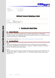
Figure 1.2: Flow-chart of the modules for shaft and bearing calculation in <strong>KISSsoft</strong>
Chapter 1 I-28 Description of the calculation modules<br />
3.2 W01 Shafts base module<br />
Allows to start the calculation module:<br />
Shaft calculation [W010]<br />
In this module, you can input and correct geometry and material data, shaft specifications,<br />
drawing numbers, bearing types, peripheral conditions, external forces and<br />
moments (simplified input for couplings, cylindrical and bevel gears, worms, worm<br />
gears, belt pulleys), interface to CAD. Graphical interface: The shaft contour and<br />
bearing are shown in a scale diagram.<br />
Additional properties of the base module are:<br />
Any dimensions (cylindrical and conical), axial symmetric cross-section, solid<br />
and hollow shafts, beams (H-, I-,L-profiles etc.)<br />
Integrated drawing tool that allows simple corrections to be made to the shaft<br />
contour (diameter, lengths). You can change any of these elements by simply<br />
clicking on them with the mouse.<br />
List functions: The elements you input are output as a list and can be changed<br />
as required (change, insert, delete)<br />
You can enter these values for force and moment in any spatial positions, however,<br />
the following values are already predefined:<br />
<br />
<br />
<br />
<br />
<br />
<br />
<br />
<br />
<br />
<br />
<br />
<br />
Cylindrical gear<br />
Bevel gear<br />
Worm/worm gear<br />
Coupling/motor<br />
Rope or belt pulley<br />
Individual radial and axial forces, bending and torsional moments<br />
External load<br />
Eccentric force<br />
Power loss<br />
Interface used to import data from gear calculations<br />
Forces can also apply outside the shaft<br />
You can also specify your own power or torque<br />
Statically undefined bearings<br />
Calculation of:
Chapter 1 I-29 Description of the calculation modules<br />
<br />
<br />
<br />
<br />
<br />
<br />
Shaft weight<br />
Moment of inertia<br />
Gyroscopic moment<br />
Resulting, axial force<br />
Static torsion of the shaft<br />
Torsional moment progression<br />
All force elements (external force, cylindrical gear, coupling etc.) can be assigned<br />
load spectra. This information is evaluated accordingly (bending,<br />
strength, roller bearing) in the calculations. Calculation with a load spectrum<br />
requires W01s<br />
The geometric data and the calculated bearing strengths are displayed in an<br />
easy to understand form.<br />
Interface to different CAD systems for transferring shaft geometry (import and<br />
export) in different formats (see options for K05).<br />
The results of the base calculation, the bending (W03), critical number of rotations<br />
(W04) and strength calculation (W06) including the specific relevant<br />
graphical representations are grouped together in an overall report.<br />
3.3 W01a Input data for several shafts<br />
Use this calculation module to input and calculate data for several coaxial shafts.<br />
You can connect the shafts with roller bearings or general links.<br />
You may need to use several coaxial shafts, for example, for idler gears for speed<br />
change gear units where the deformation of the shaft and the idler gear can be taken<br />
into account when you arrange the tooth trace corrections.<br />
At present, you can define a maximum of 15 coaxial shafts.<br />
3.4 W01b Bearing offset, Bearing clearance<br />
If you have this authorization you can take the bearing offset and the bearing clearance<br />
into account in the calculation. You can specify the bearing offset both for<br />
general bearings and for roller bearings.<br />
In the case of roller bearings, you can define a radial clearance and a displacement<br />
in both X and Z directions. In the case of general bearings, you can define clearance<br />
or displacement for all six degrees of freedom.<br />
3.5 W01c Take into account contact angle<br />
Use this calculation module to take the bearing contact angle into account in the<br />
calculation. For this purpose, the bearing force from the center point of load appli-
Chapter 1 I-30 Description of the calculation modules<br />
cation is moved along the effective line to the bearing centre. The resulting bending<br />
moment is then effective at the bearing.<br />
3.6 W01s Load spectra<br />
Use this calculation module to define load spectra that can then be taken into account<br />
in the calculation. You can either select a spectrum element, which allows<br />
you to perform all the calculations, or perform the calculation with the entire spectrum<br />
to calculate either the bearing service life (W05) or the strength of the shaft<br />
(W06s).<br />
3.7 W03 Calculate bending and bearing for c-<br />
es<br />
Calculate the deflection line, course of transverse force and course of flexural<br />
moment in the XY and the ZY plane (shaft axes always along the Y axis) with<br />
or without considering the dead weight<br />
Calculate the axial force taking into account the weight (depending on the spatial<br />
position of the shaft)<br />
Calculate the axial strain of the shaft<br />
Graphical display of all critical dimensions on screen and as a printout: course<br />
of deflection, shearing force, bending moment in different planes, torsional<br />
moment, axial force and static comparative stress<br />
Calculate the forces and moments in bearings for an unlimited number and any<br />
type of bearing<br />
Output the bearing reaction forces for an unlimited number of bearings<br />
Calculate the inclination of the deflection line in bearings, e.g. when calculating<br />
cylindrical roller bearings. The progression of the angle of inclination can<br />
also be displayed on screen and printed out.<br />
If you input a shaft with load spectra, you can also calculate the deflection lines<br />
individually for the load on each load spectrum element (authorization W1s).<br />
Calculate all stress components (tension/compression, bending, shearing, torsion)<br />
and equivalent stress. Display the equivalent stress progression as well as<br />
stress components.<br />
Calculate the bending with or without taking into account deformation due to<br />
shearing (authorization W3a)<br />
For the calculation of bending and the values in the cross sections a finite element<br />
calculation with one-dimensional bar elements is applied. This calculation is based<br />
on a CM2 FEM library of Computing Objects (http://www.computing-objects.com)
Chapter 1 I-31 Description of the calculation modules<br />
3.8 W03a take into account deformation due<br />
to shearing<br />
Deformations due to shearing can be taken into account when you calculate deformations.<br />
You can specify the shear correction coefficient for that purpose. However,<br />
there is only one shear correction coefficient for the shaft system.<br />
3.9 W03b Non-linear shaft<br />
You can activate a calculation with a geometric non-linear bar model. A shaft calculation<br />
with two fixed bearings under shearing force then also supplies axial force<br />
due to elongation along the length. If you perform the calculation with a non-linear<br />
shaft model, you must take the deformations due to shearing into account. In standard<br />
shafts, the linear and non-linear calculations return the same results. The nonlinear<br />
method supplies good results in cases that do not occur in mechanical engineering,<br />
such as, for two fixed bearings or for the calculation of the diagrams of<br />
bending for thin wires.<br />
3.10 W03c Heat expansion<br />
Input the temperature and heat expansion coefficient to define the axial expansion<br />
of temperature and housing. It is assumed that a shaft has a homogenous temperature.<br />
3.11 W03d non-linear stiffness<br />
The stiffness of roller bearings is calculated in accordance with ISO/TS 16281<br />
(DIN ISO 281 supplement 4). The internal geometry data is taken from the roller<br />
bearing database or approximated from the load numbers, if not otherwise specified.<br />
This calculation option supplies a changed bending and load distribution on<br />
the bearing, but no additional results. For more information, see W05b and W05c.<br />
You can take into account the non-linear bearing stiffness for spherical roller bearings,<br />
single-row cylindrical roller bearings, tapered roller bearings, grooved ball<br />
bearings, angular contact bearings, radial four-point bearings, deep grooved thrust<br />
ball bearings and angular contact thrust ball bearings.<br />
3.12 W04 calculation of the critical speeds<br />
Calculate the natural modes for the system of coaxial shafts, with or without additional<br />
mass.<br />
Calculate any number of natural modes<br />
Taking into account bending, torsion and axial movements<br />
Coupling of axial and bending movements by angular contact ball bearings and<br />
tapered roller bearings
Chapter 1 I-32 Description of the calculation modules<br />
Display on screen and print out natural frequencies for deflections and displacement<br />
In the case of beam profiles, natural modes are defined in both main coordinate<br />
planes.<br />
Gears can be included automatically and handled like masses. In this situation,<br />
<strong>KISSsoft</strong> takes into account the mass and the moments of inertia of the gear<br />
sited on the shaft.<br />
3.13 W04x gyro effect<br />
Prerequisite: authorization W04<br />
Addition used to calculate natural modes: This takes into account the gyro effect of<br />
large momentums of mass. The critical speed (bending mode) is calculated for<br />
forward and backward spin. In a synchronous forward spin, an unbalance increases<br />
the bending oscillations because the angular speeds of the rotating shaft and angle<br />
speed of the shaft’s peripheral centre point are the same. The backward spin is, in<br />
most cases, not technically important.<br />
The gyro effect of spinning is taken into account for the pre-defined speed.<br />
3.14 W05 cylindrical roller bearing and roller<br />
bearing service life<br />
Allows to start the calculation module:<br />
Roller bearing calculation [W050]<br />
Calculation of:<br />
Grooved ball bearing (single and double row)<br />
Angular contact bearing (single and double row)<br />
Cylindrical roller bearing (single and double row)<br />
Needle roller bearing<br />
Spherical roller bearing, Self-aligning ball bearing<br />
Tapered roller bearing<br />
Paired tapered roller bearing<br />
Four-point bearing (QJ)<br />
Spherical roller axial bearing<br />
Cylindrical roller axial bearing
Chapter 1 I-33 Description of the calculation modules<br />
<br />
<br />
<br />
Axial needle roller bearing<br />
Axial grooved ball bearing<br />
Axial angular contact bearing<br />
All data (approximately 18,000 different bearings) is stored; transferred directly<br />
from data from F<strong>AG</strong>, SKF, NSK, Koyo, Timken, IBC and KRW bearings.<br />
For integrating aditional bearings you can use the database tool<br />
Selecting a bearing by inside or outside diameter<br />
Taking into account radial and axial forces<br />
Calculate service life and static safety factor<br />
Check the bearing speed limit (oil and grease lubrication)<br />
Simultaneous calculation of up to 8 bearings (arbitrary number in shaft calculation)<br />
Bearing clearance: normal / C3 / C4 for grooved ball bearings<br />
Bearing arrangement: single, O or X arrangement.<br />
Calculate the axial forces for angular contact bearings and tapered roller bearings<br />
3.15 W05a Bearing load spectra<br />
Calculate the service life as specified in ISO 281 for arbitrary load spectra. Enhanced<br />
service life calculation (influence of operating conditions and lubricant):<br />
Roller bearing calculation is performed using the a ISO factor (ISO 281-2007), in<br />
accordance with the extended service life criterion. <strong>KISSsoft</strong> uses data about lubricant<br />
viscosity, cleanliness, operating temperature, speed, the bearing geometry and<br />
the bearing type to define the a ISO factor and then includes this in the calculation.<br />
Alternatively, you can also perform this calculation without the a ISO factor.<br />
You can also use this module to perform an enhanced bearing service life calculation<br />
in the shaft calculation.<br />
Calculate the reference thermal limit of operating speed as specified in E-DIN 732-<br />
1 and E-DIN 732-2 from the heat level of the roller bearing.<br />
3.16 W05b reference service life as specified<br />
in ISO/TS 16281<br />
Prerequisite: W03d authorization<br />
In the shaft calculation, in the enhanced version of module W03d, you can also<br />
calculate and output the reference service life specified in ISO/TS 16281. This
Chapter 1 I-34 Description of the calculation modules<br />
method performs a detailed calculation of the bearing service life and takes into<br />
account the internal bearing geometry (rolling body, clearance, etc.).<br />
This calculates the reference service life Lnrh. With authorization W05a you can<br />
also calculate the modified reference service life.<br />
As before, you can still analyze the following bearing types whilst taking their internal<br />
geometry into account:<br />
Deep groove ball bearing<br />
Angular contact ball bearing<br />
Cylindrical roller bearing<br />
Taper roller bearing<br />
Spherical roller bearings<br />
Needle roller bearing/Needle cage<br />
Axial cylindrical roller bearing<br />
Axial spherical roller bearings<br />
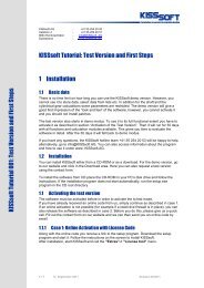
3.17 W05c Load distribution in the be aring<br />
Prerequisite: authorization W03d<br />
In the shaft calculation in combination with modules W03d and W05b you can also<br />
calculate and output the pressure of the individual rolling element as specified in<br />
ISO/TS 16281. You can output this data either as a report or a graphic.<br />
Figure 1.3: Load distribution in the bearing
Chapter 1 I-35 Description of the calculation modules<br />
3.18 W06 Calculate the service life and st atic<br />
calculation of cross-sections<br />
You can select the following cross-section types (automatic calculation of<br />
notch factors, effect of notch on the outside or inside diameter):<br />
<br />
<br />
<br />
<br />
<br />
<br />
<br />
<br />
<br />
<br />
<br />
<br />
<br />
<br />
Smooth shaft<br />
Shoulder<br />
Shoulder with relief groove<br />
Conical shoulder<br />
Interference fit<br />
Key<br />
Splines<br />
Straight-sided splines<br />
Square groove<br />
Circumferential groove<br />
V-notch<br />
Thread<br />
Cross holen<br />
Define your own definition notch factors<br />
Supplied materials: about 100 materials, such as CK 45, Ck 60, St 52, 16 MnCr<br />
5, 18 CrNiMo7, GG 20, stainless steels, steel castings, malleable iron and<br />
many more<br />
Showing the course of the equivalent stress as a graphic makes it easier to locate<br />
the cross-sections that are critical.<br />
Input the values for surface roughness and quality as defined in ISO 1302 and<br />
output roughness Rz.<br />
Influence of surface treatments (shot-peening etc.) and heat treatments.<br />
Key tables for cross-sections with keyways are pre-installed. The data is imported<br />
from a data file that contains the ISO 773, DIN 6885.1, DIN 6885.2 and<br />
DIN 6885.3 standards. You can also specify other standards, or input them directly<br />
whilst the program is running.<br />
Calculate safety for fatigue; Static safety against yield point and fracture. With<br />
W06s, finite life calculation and load spectra.
Chapter 1 I-36 Description of the calculation modules<br />
3.19 W06a calculation method Hänchen + D e-<br />
cker<br />
Calculate according to "Neue Festigkeitsberechnung für den Maschinenbau " by<br />
Hänchen + Decker. Well proven, calculation method although it no longer corresponds<br />
to the latest research results (accepted by TÜV).<br />
3.20 W06b calculation method DIN 743<br />
Calculate in accordance with DIN743 (2000 edition) "Tragfähigkeit von Wellen<br />
und Achsen" (similar to the calculation according to FKM guidelines): Strength<br />
calculation for shafts and axes with proof of fatigue safety/deformation. The stresses<br />
that occur (only mean stresses and amplitudes) are evaluated on the basis of a<br />
simplified Smith diagram.<br />
Important features of this method:<br />
applies only to shafts and axes.<br />
Tension/compression, bending and torsion are included in the calculation.<br />
However, shearing is not taken into account.<br />
Take into account surface factor (nitriding, case-hardening, carbonitriding, rolling,<br />
shot-peening, induction and flame-hardening).<br />
As the service life is not calculated (finite life time domain) the load spectra<br />
are therefore also not calculated<br />
Temperature range: -40 to 150 degrees.<br />
Only applies to steel.<br />
3.21 W06c Calculation methods according to<br />
the FKM Guideline<br />
The FKM Guideline is the most comprehensive currently-available calculation<br />
method. It goes far beyond the application areas of DIN 743, but requires more<br />
time and effort to interpret its results. The calculation algorithm performs both a<br />
static and a finite life calculation. This calculation algorithm was developed by<br />
Professor Haibach.<br />
3.22 W06s Strength calculation with load<br />
spectra<br />
Prerequisite: authorization W06b or W06c<br />
The calculations specified in the FKM guideline, or DIN743 with the FVA proposal<br />
or new draft allow you to calculate strength with load spectra. If you input a<br />
shaft with load spectra, you can use it to perform the calculation directly. However,
Chapter 1 I-37 Description of the calculation modules<br />
the calculation method specified by Hänchen/Decker does not take load spectra<br />
into account because the standard does not allow this.<br />
3.23 W07 Hydro-dynamic radial journal be arings<br />
Calculation of hydro-dynamic radial journal bearings in stationary operation. Different<br />
oil types are pre-defined (ISO VG) and you can also input data for special<br />
lubricants. The calculation is performed for cylindrical bore journal bearings (however,<br />
using different construction types only gives a small variation in results)<br />
3.24 W07a calculation in accordance wit h<br />
Niemann<br />
This method calculates the power loss, oil flow, oil temperature, minimum lubricant<br />
gap thickness according to Niemann, Maschinenelemente I, Springer, and according<br />
to O. R. Lang, Gleitlager, Springer. This calculation can only be used for<br />
pressure lubricated bearings (circulatory lubrication) and also checks for operating<br />
reliability.<br />
3.25 W07b calculation according to DIN 31652<br />
Calculation according to DIN 31652: Complete calculation according to 31652,<br />
parts 1 to 3 (1983 edition) for pressure-less and pressure lubricated bearings. This<br />
takes into account the way in which lubricant is applied (lubrication holes, lubrication<br />
groove, lubrication glands). It calculates all the operating data in accordance<br />
with DIN 31652, including the operating temperature, minimum lubrication gap<br />
width, power loss, oil flow etc. It also checks operating reliability. In adition the<br />
spring stiffness (radial stiffness) of the bearing at the operating point is calculated.<br />
This value can then be included in the shaft calculation.<br />
3.26 W08 Grease lubricated radial journal<br />
bearings<br />
Calculates the bearing data in operation and during the transfer to mixed friction on<br />
the basis of the calculation method used for oil lubricated journal bearings when<br />
insufficient lubricant is present. A wide range of different greases are pre-defined<br />
here.<br />
3.27 W07c Hydrodynamic axial journal bearing<br />
Calculation of hydrodynamic axial journal bearings in stationary operation. Different<br />
oil types are pre-defined (ISO VG) and you can also input data for special lubricants.<br />
Calculation according to DIN 31653: Complete calculation of axial segment<br />
bearings according to 31653, parts 1 to 3 (1991 edition) for pressure-less and
Chapter 1 I-38 Description of the calculation modules<br />
pressure lubricated bearings. It calculates all the operating data in accordance<br />
with DIN 31653, including the operating temperature, minimum lubrication<br />
gap width, power loss, oil flow etc.<br />
Calculation according to DIN 31654: Complete calculation of tilting-pad thrust<br />
bearings according to 31654, parts 1 to 3 (1991 edition) for pressure-less and<br />
pressure lubricated bearings. This takes into account the way in which lubricant<br />
is applied (lubrication holes, lubrication groove, lubrication glands). It calculates<br />
all the operating data in accordance with DIN 31654, including the operating<br />
temperature, minimum lubrication gap width, power loss, oil flow etc.<br />
3.28 W10 Tooth trace correction<br />
Calculates the shift of a cross-section point from its home position due to torsion<br />
and bending. For various purposes, for example, for grinding off crowning (also<br />
called length or flank line correction) on toothing, it is important that you know<br />
how much a specific point in the shaft cross-section moves in a particular direction<br />
due to elastic deformation. This program calculates the shift in a specific interval<br />
along the length of the axis and prints out the data. The tooth trace deviation due to<br />
deformation is also calculated for toothing. This value is needed for precise cylindrical<br />
gear calculations. Graphical display of deformation components on screen<br />
(and printer). You can transfer this data to any CAD program via the graphic interface.<br />
3.29 W12 Shaft arrangement (integrated d e-<br />
sign tool)<br />
Shaft sizing:<br />
The system has two functions which you can use to size shafts (of any diameter):<br />
Sizing for strength: The <strong>KISSsoft</strong> system arranges the shaft contour so that the<br />
equivalent stress has the same (definable) value in all the cross-sections.<br />
Sizing for deflection: The <strong>KISSsoft</strong> system changes the diameters of the default<br />
shaft contour proportionally to achieve a pre-defined maximum deflection.<br />
Procedure shaft optimization:<br />
The "traditional" method of design leads from the idea to the design to rough-sizing<br />
and then to the draft design. This can be replicated very effectively by the <strong>KISSsoft</strong><br />
system when it is implemented in a CAD environment. As soon as a design concept<br />
is available, the next step usually involves dimensioning the load bearing elements,<br />
such as couplings, gears, belts etc. The <strong>KISSsoft</strong> system provides a wide<br />
range of layout programs for this. The dimensions of the load bearing elements<br />
then result in the bearing distances and the shaft lengths. The <strong>KISSsoft</strong> system has
Chapter 1 I-39 Description of the calculation modules<br />
a layout module that you use to dimension shafts with support. Start the shaft calculation<br />
program, enter the approximate shaft length, the bearing mid-points and<br />
elements with external forces. The system then returns a first suggestion for the<br />
diameter. You can then define the type of bearing and, depending on the required<br />
service life, you can modify the shaft diameter. You can easily exit from, or correct<br />
the appropriate diameter change in the graphical display on the screen.<br />
In the next step, you calculate the exact strength (check for strength against overload<br />
failure and failure due to fatigue). As part of the strength calculation process,<br />
the outside shaft diameter is optimized automatically to achieve the required level<br />
of safety. You can, of course, also check the shaft-hub connections (press fit, key,<br />
couplings with toothing) at the same time.<br />
You can now output this quickly calculated and optimally arranged shaft with support<br />
via the CAD interface and, without any additional effort, you now have the<br />
finished shaft contour, together with the bearings, in your CAD design drawing.
Chapter 1 I-40 Description of the calculation modules<br />
3.30 W13 Buckling<br />
You use this function to calculate the buckling load of shafts and supports. All peripheral<br />
conditions, bearings and effective axial forces (point or line loads) are taken<br />
into account in the calculations. It outputs the safety for a number of buckling<br />
situations, however, only the first one is usually relevant. You must input the loads<br />
for this calculation.
Chapter 1 I-41 Description of the calculation modules<br />
4 Machine elements - M module<br />
4.1 M01a Cylindrical interference fit<br />
Cylindrical interference fits influenced by centrifugal force<br />
Loading in circumferential and axial directions<br />
Calculating the maximum torque for a non-slipping fit. If slip occurs in the fit,<br />
micro gliding will cause corrosion due to friction.<br />
The calculation includes the entirety of the DIN 7190 standard (elastics) with<br />
longitudinal, radial and oil interference fits<br />
This module also calculates the safety of the interference fit against gliding and the<br />
safety of the shaft material and the hub are to fracture and yielding. The tolerance<br />
system in accordance with DIN 7151 (e.g. with diameter input 60 H7/f6), has been<br />
implemented to make it easier to input data.<br />
4.2 M01b Conical interference fit<br />
Conical interference fit connection: Calculation and design of a conical interference<br />
fit connection for transferring torque in an elastic operating state. Conical interference<br />
fits are normally joined axially with a screw or by pressing them together.<br />
Calculation method as specified by F. G. Kollman for connections with the<br />
same Young's modulus and with a solid inner part. The permitted area of the set<br />
angle is determined (for the upper installation). The displacement and pretension<br />
force for joints and in operation under maximum torque is also calculated.<br />
Sizings:<br />
Permitted angle of taper (for self locking)<br />
Length of interference fit for transmitting the maximum torque<br />
Maximum transmissible torque<br />
4.3 M01x Additional function for a press fit<br />
Extension of the interference fit calculation:<br />
The calculation also takes into account the effect of the centrifugal force on the<br />
expansion of the interference fit and on the stress in the shaft and hub.<br />
You can either enter the tolerance manually, or use an automatic option to calculate<br />
the tolerance pairing based on the required safety against gliding and the
Chapter 1 I-42 Description of the calculation modules<br />
permissible material stress. Input the values for surface roughness with qualities<br />
defined in ISO 1302.<br />
You can define a hub with varying outside diameter in <strong>KISSsoft</strong> to calculate<br />
cylindrical and conical interference fits. In such cases, input the outside diameter<br />
section by section with the diameter and length. The system then derives an<br />
equivalent diameter from these values (as specified by V. Gross) and includes<br />
it in the calculation.
Chapter 1 I-43 Description of the calculation modules<br />
4.4 M01c clamped connections<br />
There are two different configurations of clamped connections that can be calculated:<br />
Slotted hub<br />
Split hub<br />
The surface pressure and safety against sticking are calculated in accordance with<br />
the classic literature (Roloff Matek, Machine elements, 15th Edition, 2001). Bending<br />
is calculated as specified by Decker, Machine elements, 15th Edition, 2000.<br />
4.5 M02a Key / Key way<br />
For keys as defined in:<br />
DIN 6885.1<br />
DIN 6885.2<br />
DIN 6885.3<br />
ANSI B17.1 Square<br />
ANSI B17.1 Rectangular<br />
Own definition<br />
a calculation is performed to find the load on the shaft and hub (surface pressure)<br />
and the key (shearing) and also defines the safeties (calculation method: DIN 6892<br />
(1998) method C). The calculation takes into account the tolerances of the key radii<br />
and the direction of force. You can also enter your own value for the number of<br />
keys and the operating factor. Scale graphic representation<br />
Key calculation as specified by DIN 6892 (1998) method B:<br />
This standard uses very clearly defined calculations for keys under constant and<br />
peak load. For example, it also includes the situation where an interference fit is<br />
present. You can input this data in a sub dialog: Chamfer on shaft and the hub;<br />
smaller and larger outside diameter of the hub; width to outside diameter; distance;<br />
torque curve; frequency of load direction change.<br />
Sizings:<br />
Determine the load bearing length of the shaft or hub on the basis of target<br />
safety and<br />
determine the transmissible torque.
Chapter 1 I-44 Description of the calculation modules<br />
4.6 M02b Straight-sided spline/ Multi-groove<br />
profile<br />
For multi-groove profiles specified in:<br />
DIN ISO 14 (light series)<br />
DIN ISO 14 (medium series)<br />
DIN 5464 (vehicles, heavy series)<br />
DIN 5471 (machine tools, with 4 keys)<br />
DIN 5472 (machine tools, with 6 keys)<br />
a calculation is performed to find the load placed on the shaft and hub (surface<br />
pressure). You can also add additional standards. The calculation of the load placed<br />
on the shaft and hub (surface pressure) together with determining the safeties is<br />
performed in accordance with the "classic technical literature" (Niemann, Maschinenelemente<br />
I, 4th Edition, 2005). Scale graphic representation.<br />
Sizings:<br />
Determine the load bearing length of the shaft or hub on the basis of target<br />
safety and<br />
determine the transmissible torque.<br />
4.7 M02c Spline<br />
For splines defined in:<br />
DIN 5480<br />
DIN 5481<br />
DIN 5482<br />
ISO 4156 (1991)<br />
ANSI B92.1 and ANSI B92.2 (1992)<br />
a calculation is performed to find the load placed on the shaft and hub (surface<br />
pressure). You can also add additional standards. Toothing data is defined in the<br />
database and therefore you can make the use of in-house profiles mandatory. Use<br />
module Z09 of the gear calculation to calculate manufacturing data and tolerances.<br />
The calculation of the load placed on the shaft and hub (surface pressure) together<br />
with determining the safeties is performed in accordance with the "classic technical<br />
literature" (Niemann, Maschinenelemente I, 4th Edition, 2005).<br />
Sizings:
Chapter 1 I-45 Description of the calculation modules<br />
Determine the load bearing length of the shaft or hub on the basis of target<br />
safety and<br />
determine the transmissible torque.<br />
4.8 M02d Polygon<br />
For polygon shafts specified in:<br />
DIN 32711-1 (P3G profile)<br />
DIN 32712-1 (P4C profile)<br />
a calculation is performed to find the load placed on the shaft and hub (surface<br />
pressure). You can also add additional standards. The calculation of the load placed<br />
on the shaft and hub (surface pressure) together with determining the safeties is<br />
performed either in accordance with DIN standards 32711-2 (for P3G profiles)/<br />
DIN 32712-2 (for P4C profiles) or with the "classic technical literature" (Niemann,<br />
Maschinenelemente I, 4th Edition, 2005).<br />
Scale graphic representation according to DIN standards<br />
Sizings:<br />
Determine the load bearing length of the shaft or hub on the basis of target<br />
safety and determine the transmissible torque<br />
4.9 M02e Woodruff key<br />
For Woodruff keys specified in:<br />
DIN 6888, series A (high pinion groove)<br />
DIN 6888, series B (low pinion groove)<br />
a calculation is performed to find the load placed on the shaft and hub (surface<br />
pressure). You can also add additional standards. The calculation of the load placed<br />
on the shaft and hub (surface pressure) together with determining the safeties is<br />
performed in accordance with the "classic technical literature" (Niemann, Maschinenelemente<br />
I, 4th Edition, 2005).<br />
Sizings:<br />
Determine the load bearing length of the shaft or hub on the basis of target<br />
safety
Chapter 1 I-46 Description of the calculation modules<br />
4.10 M03a Pin calculation<br />
Pin/spike connections are split into five calculations types, depending on the application<br />
case:<br />
Cross pin under torque<br />
Longitudinal pin under toque<br />
Guide pin under bending force<br />
Pin connection subjected to shearing action<br />
Pins in a circular layout<br />
The calculation of the load placed on pin shaft and hub (or part) together with determining<br />
the safeties is performed in accordance with the "classic technical literature"<br />
(Niemann, Maschinenelemente I, 4th Edition, 2005), apart from pins in a circular<br />
layout.<br />
You can select solid pins, notched pins, as well as spiral pins as specified in DIN<br />
EN ISO 8748, DIN EN ISO 8750, DIN EN ISO 8751 and spiral pins as specified in<br />
DIN EN ISO 8752, DIN EN ISO 13337 as required.<br />
4.11 M04 Bolt calculation<br />
The calculation permits the use of the entire scope of VDI 2230, 2003 Edition. If<br />
used together with the M04a option, you can, for example, calculate the complex<br />
examples of VDI 2230 quickly and effectively. Tables have been integrated for all<br />
the elements concerned, such as bolts specified in ISO 4762, 4017, 949 and ASME<br />
18.2.1, standards for bores, washers, nuts etc. You can also define your own bolts<br />
with up to 8 sections, as well as hollow bolts. You can define plates, bushes, annulus<br />
segments or prismatic bodies as clamped parts. The program is able to make<br />
suggestions for the reference diameter and thread length. The default pretension<br />
force is 90% of the yield point, however, you can use the setting options to modify<br />
this. You can also perform calculations with a pre-defined starting torque or pretension<br />
force. Data is output for the state with the minimum pretension force (tightening<br />
factor 1.0), with the maximum pretension force and for the selected utilization<br />
of the yield point. The tension diagram and bolt geometry are shown as a<br />
graphic on screen and can then either be printed out or transferred to a CAD program.<br />
4.12 M04a Eccentric clamping and load, co n-<br />
figurations (for M04)<br />
This in addition allows you to take into account an eccentric load and clamping. It<br />
checks for yawning in the joint. Configurations: This option also allows the input<br />
of bolt configurations with axial, transverse and bending moment loads. Minimum<br />
length of engagement and stripping strength: To determine the necessary minimum
Chapter 1 I-47 Description of the calculation modules<br />
length of engagement, you can (as specified in section 5 of VDI 2330), calculate<br />
the stripping strength of bolts and nut threads whilst taking into account the nut<br />
expansion and plastic deformation.<br />
4.13 M04b Bolt calculation at high and low<br />
temperatures (for M04)<br />
Bolts are usually mounted at ambient temperature. However, the operating temperature<br />
has a significant influence on the pretension state of the bolt and therefore<br />
also on the safety of the connection. For example, if steel bolts are inserted into<br />
light metal materials the conditions change dramatically, even at 70 degrees! The<br />
extension to <strong>KISSsoft</strong>'s bolt calculation function allows it to be used in the calculation<br />
standard specified in VDI 2230, which also calculates bolt connections for operating<br />
temperatures between -200 and +1000 degrees Celsius. You can specify<br />
different temperatures for the bolt and the clamped parts. You can also take into<br />
account the temperature-dependent changes in the Young's modulus, in the thermal<br />
expansion coefficients, in the yield point and in the pressures permitted for the materials.<br />
All the criteria for the bolt connection are checked for assembly status at<br />
ambient temperature as well as for stationary or non-stationary status at operating<br />
temperature (in accordance with VDI 2230: preload, bolt load, endurance limit and<br />
surface pressure).<br />
4.14 M08 Welded joints<br />
Calculation basis: DIN 18800, Part 1, November 1990 Edition, especially Section<br />
8.4. Calculation and design of welded joints (joints with electric arc welds) with<br />
welded seam types:<br />
Butt seam through welded<br />
Double HV welded seam, counter welded<br />
HV welded seam, cap position counter welded/root through welded<br />
HY-seam with or without fillet weld, not through welded<br />
Double-HY-seam with or without fillet weld, not through welded<br />
Double-I-seam, not through welded<br />
Fillet weld, not through welded<br />
Double-fillet weld, not through welded<br />
Input the load (normal force, shearing forces), the part safety coefficient and the<br />
weld seam boundary coefficient, integrated material database. Calculates the<br />
stresses, the weld seam boundary stress and safety.
Chapter 1 I-48 Description of the calculation modules
Chapter 1 I-49 Description of the calculation modules<br />
4.15 M09a Glued and Soldered Joints<br />
Glued joint:<br />
Calculation basis: G. Niemann, Maschinenelemente, Volume I, 1981. The calculation<br />
of glued joints is performed for joints that are subject to shear load.<br />
Two different load cases are described:<br />
Shearing force: Transmission of shearing force between two surfaces<br />
Torque: shaft hub joint with a torque load<br />
The joint can be subject either to static or dynamic (usually pulsating) load. You<br />
can select adhesives (extendable database) that harden at room temperature or at<br />
higher temperatures.<br />
Sizings:<br />
Sizing the adhesion width (for shaft hub), or the adhesion length (for brackets),<br />
on the basis on the strength of the underlying material. The tear resistance of<br />
the connection is set so that it corresponds to the tear resistance of the underlying<br />
material or the fatigue strength under pulsating stress of the shaft.<br />
Sizing the adhesion width on the basis of stress: The tear resistance of the joint<br />
is sized so that it can withstand the forces it is subjected to without compromising<br />
the specified safety.<br />
Soldered joint<br />
Calculation basis: G. Niemann, Maschinenelemente, Volume I, 1981. The calculation<br />
is performed for soldered joints that are subject to shear load.<br />
Two different load cases are described:<br />
Shearing force: Transmission of shearing force between two surfaces<br />
Torque: shaft hub joint with a torque load<br />
The joint can be subject either to static or dynamic (usually pulsating) load. You<br />
can select any material (extendable database):<br />
Soft solder LSn40, LSn60 for short-term loads<br />
Soft solder LSn40 for a permanent load<br />
Brass solder: Steel NE heavy metals<br />
New silver solder, copper: steel<br />
Silver solder: Steel NE heavy metals<br />
Sizings:
Chapter 1 I-50 Description of the calculation modules<br />
Sizing the solder width (for shaft hub), or the solder length (for brackets), on<br />
the basis on the strength of the underlying material. The tear resistance of the<br />
connection is set so that it corresponds to the tear resistance of the underlying<br />
material or the fatigue strength under pulsating stress of the shaft.<br />
Sizing the solder width on the basis of stress: The tear resistance of the joint is<br />
sized so that it can withstand the forces it is subjected to without compromising<br />
the specified safety.
Chapter 1 I-51 Description of the calculation modules<br />
5 Springs - F-module<br />
5.1 F01 compression springs calcul ation<br />
Calculation of cylindrical stressed compression springs, as specified in EN 13906-<br />
1. Includes the sizing (by inputting the compression forces and assembly masses)<br />
and the verification of compression springs. Database with the most important<br />
spring materials. Displays the spring characteristic line, the relaxation, the progression<br />
of relaxation over time, the progression of spring force over time and the<br />
Goodman diagram for dynamically loaded springs. Tolerances and main mass<br />
specified in DIN 2076, 2077, 2096, 2097, EN 10270-1. Integrated database with<br />
spring geometries specified in DIN 2098 sheet 1.<br />
5.2 F02 tension spring calculation<br />
Calculation of cylindrical tension springs in accordance with EN 13906-2. Contains<br />
the sizing (by inputting the compression forces and assembly dimensions) and<br />
the verification of tension springs. Database with the most important spring materials.<br />
Database with wire diameters as specified in DIN 2076, 2077, EN 10270-1.<br />
Display the spring characteristic line, Goodman diagram for dynamically loaded<br />
springs. Tolerances, main mass, eyes specified in DIN 2076, 2077, 2096, 2097, EN<br />
10270-1.<br />
5.3 F03 Leg spring calculation<br />
Calculation of cylindrical rotating springs in accordance with EN 13906-3. Contains<br />
the sizing (by inputting the compression forces and assembly dimensions) and<br />
the verification of leg springs. Database with the most important spring materials.<br />
Database with wire diameters as specified in DIN 2076, 2077, EN 10270-1. Display<br />
the spring characteristic line. The leg can either be clamped in a fixed position,<br />
supported, tangential or bent. Tolerances specified in DIN 2076, 2077, EN<br />
10270-1.<br />
5.4 F04 disk spring calculation<br />
Calculation of disk springs and spring packages as specified in DIN 2092. Contains<br />
the sizing (by inputting the compression forces and assembly dimensions) and the<br />
verification of disk springs. Database with material characteristic values and dimensions<br />
specified in DIN 2093. Display the spring characteristic line, Goodman<br />
diagram.
Chapter 1 I-52 Description of the calculation modules<br />
5.5 F05 torsion bar spring calculation<br />
Calculation of torsion bar springs with round cross-section in accordance with DIN<br />
2091. Contains the sizing (by inputting the torsional moments and assembly dimensions)<br />
and the verification of torsion bar springs. Material characteristic values<br />
according to DIN 17221. Main mass specified by DIN 2091. Display the spring<br />
characteristic line.
Chapter 1 I-53 Description of the calculation modules<br />
6 Gears - Z-modules<br />
6.1 Z01 Gear - Base module<br />
Allows to start the calculation module:<br />
Single gear [Z011]<br />
Gear pair [Z012]<br />
Gear geometry calculation for cylindrical gears as specified in ISO 21771 (and<br />
DIN 3960)<br />
Valid for: internal and external toothings<br />
Spur and helical gears, herringbone gears<br />
Reference profiles specified in ISO 53, DIN 867, DIN 3972 profiles I, II, III<br />
and IV, DIN 58400 and free choice (for precision mechanics: topping tools);<br />
protuberance, buckling root flank.<br />
<br />
<br />
Input of hobbing cutters (specified in DIN 3972 and your own tool lists)<br />
and pinion-type cutters (specified in DIN 1825, 1826, 1828 and your own<br />
tool lists).<br />
Alternatively, you can also determine the tooth form as a theoretical involute<br />
without inputting tool data<br />
Taking into account tip circle changes, length corrections, chamfers, tip chamfer,<br />
profile modifications, etc.<br />
Check for undercut, a pointed tooth, meshing interference, tip clearance, ease<br />
of assembly, tip and root form diameter, active tip and root diameter (active involutes),<br />
contact outside the meshing area, etc.<br />
Calculate the control measures, tooth width, tooth thickness, effective radial<br />
measurement over one and two balls, single roller and double roller dimension.<br />
The control measures are calculated separately for each lower and upper deviation.<br />
Optional you can also determine the tooth thickness deviation:<br />
<br />
<br />
<br />
<br />
in accordance with DIN 3967 (for example, e25) (database tables installed)<br />
in accordance with ISO 1328 (for example, GJ)(1980 edition, these details<br />
are not included in the current edition)<br />
in accordance with ISO 23509 (for bevel gears)<br />
in accordance with DIN 58405 (e.g. 8g) for precision mechanics (database<br />
tables installed)
Chapter 1 I-54 Description of the calculation modules<br />
<br />
from the target circumferential backlash or from the normal backlash<br />
You can also create your own tooth thickness allowance tables. These tables<br />
are then processed automatically by the program.<br />
For precision mechanics: tip circle (with tolerances) for a topping tool<br />
Calculate the circumferential backlash (and normal backlash) of the gear pair<br />
whilst taking into account tooth thickness deviations and centre distance tolerance.<br />
Calculate all relevant values, such as contact ratio, specific sliding etc.<br />
Calculate and check the effective contact ratios and root diameters (taking into<br />
account the tooth thickness deviation); calculate all the important data for the<br />
smallest centre distance and greatest tooth thickness, as well as for the greatest<br />
centre distance and smallest tooth thickness<br />
Angles can be input either as decimal numbers with decimal points or with<br />
minutes and seconds.<br />
Modules can be input either in mm or as diametral pitch or transverse diametral<br />
pitch, transverse or normal pitch.<br />
Different toothing qualities for individual gears.<br />
Increase the interval for permitted profile shifts: you can use this authorization<br />
to significantly increase the bandwidth of the usual permitted profile shifts.<br />
This is very useful for special cases.<br />
You can also calculate power loss, moment of inertia and weight for all types<br />
of strength calculations (for cylindrical gears, bevel gears, worm gears).<br />
Materials and reference profiles are taken from the database<br />
You can define any number of different materials and reference profiles in special<br />
data base entries. At present, the system is shipped with approximately 220 different<br />
materials and a wide and varied range of reference profile, hobbing cutter and<br />
pinion-type cutter lists. All the hardening techniques specified in DIN 3990 are<br />
taken into account. <strong>KISSsoft</strong> also supports the use of stainless steels, aluminum,<br />
bronzes etc. Plastics with module Z14.<br />
6.2 Z01x extension of cylindrical gear ge ometry<br />
Extension for calculation modules: Z011, Z012, Z013, Z014, Z015, Z016
Chapter 1 I-55 Description of the calculation modules<br />
Profile shift layout (optimum area, balanced sliding etc.). Deer and stub toothing,<br />
topping tool. Special report with all manufacturing tolerances ISO 1328, DIN 3961,<br />
<strong>AG</strong>MA 2015, <strong>AG</strong>MA 2001, DIN 58405, BS 436; Calculate tolerances/deviations<br />
from measured values<br />
Preliminary treatment tool and input for preliminary treatment: Input the preliminary<br />
treatment tool with grinding allowance, along with the grinding wheel (tip<br />
rounding and grinding depth: up to the form diameter or active tip and root diameters,<br />
or own input). All the control measures for preliminary and final treatments,<br />
the tooth form for preliminary and final treatment, the grinding notch (if one is<br />
produced and if this reduces the strength for the strength calculation as specified in<br />
ISO6336 or DIN3990) are calculated and documented. Manufacturing processes<br />
involving more than two processing steps (for example, two cutting processes plus<br />
a grinding process) are performed with authorization Z051.<br />
Define form diameters from the tooth form: The tip and root form diameters are<br />
usually calculated according to the theoretical equations in ISO21771. However,<br />
this does not take into account the effective undercut. If you activate the "Calculate<br />
tip and/or root form diameter from tooth form" option, the form diameter is determined<br />
on the basis of the effective tooth form. In the case of toothing with an undercut,<br />
this option determines the starting point of the undercut and includes it in<br />
the calculation used to determine the transverse contact ratio etc.<br />
NOTE:<br />
In the case of toothing with profile modifications, the starting point of the correction<br />
is displayed, to allow the transverse contact ratio to be displayed as being too<br />
small.<br />
Determine the tooth thickness in any diameter: Report of tooth thickness (chord<br />
and arc with deviation) at any diameter.<br />
6.3 Z19h Sizing of deep toothing<br />
Extension for calculation modules: Z012, Z013, Z014, Z015, Z016<br />
Special reference profiles with larger addendums and dedendums are used for deep<br />
toothing. This sizing function calculates the required standard basic rack tooth profile<br />
on the basis of the required transverse contact ratio. If this function is active in<br />
gear fine sizing, the reference profile for every solution is calculated so that precisely<br />
the target transverse contact ratio is achieved.
Chapter 1 I-56 Description of the calculation modules<br />
6.4 Z15 Calculate the details used to modify<br />
the profile of cylindrical gears<br />
Extension for calculation modules: Z012, Z013, Z014, Z015, Z016<br />
Calculation of points A to E along the path of contact with the corresponding involute<br />
lengths. Output the diameter, radii, involutes and pitch lengths for the involute<br />
test diagram (for the gear and its paired opposing gear). Input all reference values<br />
in accordance with the different methods used to calculate tip relief. <strong>KISSsoft</strong> proposes<br />
a tool that can be used to generate the profile modification. You can get the<br />
data in the tooth form calculation. Short or long correction length, tip and/or root<br />
relief, specify the load for which the sizing is to be calculated.<br />
6.5 Z19a Calculation with operating cente r<br />
distance and profile shift according to<br />
manufacture<br />
Extension for calculation modules: Z012, Z013, Z014, Z015, Z016<br />
The cylindrical gear specified in ISO 21771 or DIN 3960 is based on the calculation<br />
of a (theoretical) backlash-free meshing. This enables the total addendum<br />
modifications for the individual gears over the centre distance to be specified. With<br />
this authorization, you can input the profile shifts independently of the center distance.<br />
This is very useful as it provides a way to check the limits of a toothing<br />
(backlash, contact ratio etc.) if there are major variations in the center distance (e.g.<br />
in the case of large center distance tolerance zones).<br />
6.6 Z19d Optimize axis centre distance with<br />
respect to balanced sliding<br />
Extension for calculation modules: Z012, Z013, Z014, Z015, Z016<br />
Optimize axis center distance with respect to balanced sliding: For a specified addendum<br />
modification of a (selectable) gear, this authorization calculates the axis<br />
center distance in such a way as to balance gear pair specific sliding (for cylindrical<br />
gears).<br />
6.7 Z19e Representation of specific sliding<br />
Extension for calculation modules: Z012, Z013, Z014, Z015, Z016, Z070
Chapter 1 I-57 Description of the calculation modules<br />
The progression of specific sliding (sliding speed and tangential speed) during the<br />
meshing can be shown as a graphic. The calculation is performed for involute cylindrical<br />
gear toothing. This shows specific sliding for the smallest centre distance<br />
and greatest tooth thickness, as well as for the largest centre distance and smallest<br />
tooth thickness.<br />
(See authorization Z27 for details on how to calculate specific sliding and the sliding<br />
movements for any tooth form and involute gears with profile modifications.)<br />
6.8 Z19f suggestion of sensible lead corre c-<br />
tions<br />
Extension for calculation modules: Z012, Z013, Z014, Z015, Z016<br />
For calculations specified in ISO (Z02a) or DIN (Z02).<br />
The ISO 6336 or DIN 3990 standards assume that flank line corrections are performed<br />
in a reasonable manner. This additional program generates reasonable sizings<br />
for lead corrections as specified in ISO 6336.<br />
6.9 Z19l Conversion of profile shift coeff i-<br />
cient and tooth thickness deviation<br />
Extension for calculation modules: Z011, Z012, Z013, Z014, Z015, Z016, Z080,<br />
Z170, Z09A<br />
With this authorization, <strong>KISSsoft</strong> can convert the profile shift coefficient from the<br />
base tangent length, measurement over balls etc. The tooth thickness deviation can<br />
also be converted in the tolerance screen.<br />
6.10 Z19n Profile and tooth trace diagrams }<br />
Extension for calculation modules: Z011, Z012, Z013, Z014, Z015, Z016, Z080,<br />
Z170, Z09A<br />
Use this authorization to display profile and tooth trace diagrams.<br />
6.11 Z02 Strength calculation as specified in<br />
DIN 3990<br />
Extension for calculation modules: Z012, Z013, Z014, Z015, Z016<br />
According to DIN 3990, December 1987 edition (most recent, valid edition)
Chapter 1 I-58 Description of the calculation modules<br />
Comprehensive, very detailed calculation using the most precise methods (method<br />
B) with the option of influencing all the most critical values.<br />
You can also use method DIN 3990, Part 41, for vehicle gears.<br />
Calculate general influencing values (DIN 3990, Part 1) with dynamic and face<br />
load factors and transverse coefficients:<br />
Face load factor for cylindrical gear pairs according to method C2 with:<br />
Load configurations shown as graphics when selected<br />
- Optionally taking into account the support effect and contact pattern check.<br />
- Load coefficients for planetary stages in accordance with method C1.<br />
- Load coefficients according to method B by the exact verification of production<br />
errors as the result of deformation with shaft calculation<br />
(authorization W10)<br />
Calculate tooth flank-load capacity (micro pitting; DIN 3990, Part 2) according<br />
to method B.<br />
Calculate root-load capacity (DIN 3990, Part 3) according to method B, tooth<br />
form- and stress correction factor, optionally also using method C.<br />
Calculate scuffing safety (DIN 3990, Part 4) with both calculation procedures<br />
(flash temperature and integral temperature criterion) according to method B.<br />
Materials specified in DIN 3990, Part 5<br />
Taking into account the influence of grinding notches. Here, you input the relationship<br />
tg/g (tg: depth of grinding notch, g: radius of grinding notch) in accordance<br />
with the Figure in DIN3990, Part 3, Chapter.4.4 or ISO6336, Part 3,<br />
Fig.33. This calculates Yg' (factor, which is multiplied with YS). If you input<br />
the preliminary and finishing tools, tg/g is calculated automatically.<br />
6.12 Z02a Strength calculation as specified in<br />
ISO 6336<br />
Extension for calculation modules: Z012, Z013, Z014, Z015, Z016<br />
The ISO 6336 standard for calculating the strength of cylindrical gears first appeared<br />
in 1996. The current edition, ISO 6336:2006, includes useful innovations.<br />
The calculation includes all the general factors (Part 1), flank safety (Part 2), root<br />
safety (Part 3), materials (Part 5) and scuffing safety (as specified in DIN 3990-4)<br />
Grinding notches are taken into account as specified in DIN 3990, (Z02). ISO 6336<br />
corresponds to a great extent to DIN 3990. However, it does have a few significant<br />
differences (primarily in the endurance limit range).
Chapter 1 I-59 Description of the calculation modules<br />
Calculate the internal temperature and the flash temperature as specified in ISO TR<br />
13989-1 and ISO TR 13989-2<br />
Corrigendum ISO6336-2 (2008): A different helix angle factor Z can be selected<br />
if required.<br />
6.13 Z02x Static strength of the tooth root<br />
Prerequisite: authorization Z2 or Z2a or Z13 or Z14<br />
Extension for calculation modules: Z012, Z013, Z014, Z015, Z016<br />
Calculate the tooth root static strength of cylindrical gears<br />
Define the tooth root stress (with and without stress correction factor YS) as specified<br />
in ISO6336, calculate safety against overload failure and against persistent<br />
deformation (yield point). For metallic materials and for plastics (tensile strength<br />
and yield point depending on temperature)<br />
6.14 Z13 Calculation using the <strong>AG</strong>MA standard<br />
(USA standard)<br />
Extension for calculation modules: Z012, Z013, Z014, Z015, Z016<br />
Calculation using a wide range of <strong>AG</strong>MA standards:<br />
You can use either the USA standards 2001-B88, 2001-C95, 2001-D04 (all in imperial<br />
units of measurement) and 2101-D04 (metric units of measurement) to calculate<br />
the strength of cylindrical gears. The standard implemented in its complete<br />
form and the dynamic factor and the face load coefficient are calculated in accordance<br />
with <strong>AG</strong>MA recommendations. You can also input your own coefficients.<br />
The geometry factors (for tooth root and flank) are calculated entirely in accordance<br />
with ANSI/<strong>AG</strong>MA 908-B89. In addition to all the relevant intermediate results,<br />
the following values are also supplied: Pitting Resistance Power Rating, Contact<br />
Load Factor, Bending Strength Power Rating, Unit Load for Bending Strength,<br />
Service Factor. This calculation can also be used for every other cylindrical gear<br />
configuration (including planetary stages). However, it is worth noting that <strong>AG</strong>MA<br />
Directives do not permit the calculation of tooth root strength in internal gear pairs.<br />
However, authorization Z19i (graphical method) does allow this to be calculated.<br />
The strength calculation specified in <strong>AG</strong>MA6004-F88 can be used for open gear<br />
rims (for example, cement mills).
Chapter 1 I-60 Description of the calculation modules<br />
Tooth form factor Y must be calculated in accordance with <strong>AG</strong>MA 908 for each<br />
type and degree of accuracy of toothing for tip load (application of force at tip) or<br />
for HPSTC (application of force at HPSTC). HPSTC is used in calculations for<br />
spur gears of high quality, otherwise, the tip load is used. However, if required, this<br />
can be overridden and you can use either tip load or HPSTC for the calculations.<br />
6.15 Z13b Calculation in accordance with A G-<br />
MA 6011/<strong>AG</strong>MA 6014 (US norm)<br />
Extension for calculation modules: Z012, Z013, Z014, Z015, Z016<br />
Strength calculation as defined in <strong>AG</strong>MA 6011-I (for turbo drives).<br />
Strength calculation as defined in <strong>AG</strong>MA6014-A06 (for large, open gear<br />
rings). <strong>AG</strong>MA6014 replaces <strong>AG</strong>MA6004-F88.<br />
6.16 Z02b Strength calculation as specified in<br />
BV RINA<br />
Extension for calculation modules: Z012, Z013, Z014, Z015, Z016<br />
Strength calculation of cylindrical gears. Special calculation method for marine<br />
applications (primarily for France and Italy), similar to ISO 6336 with a few additions.<br />
Special documentation is available on request.<br />
6.17 Z10 Cylindrical gear calculation using<br />
the FVA method<br />
Extension for calculation modules: Z012, Z013, Z014, Z015, Z016<br />
Gear strength is calculated using the gear calculation programs developed by the<br />
Forschungsvereinigung Antriebstechnik (Germany). The calculations are performed<br />
on the basis of DIN 3990, and take into account all the variations. Therefore<br />
this option achieves exactly the same results as those given by the FVA program.<br />
FVA is used as a reference program. If problems arise when comparing calculations<br />
performed using different programs, you can use the calculation with the<br />
FVA program as a reference.<br />
6.18 Z14 Plastic gears<br />
Extension for calculation modules: Z012, Z013, Z014, Z015, Z016
Chapter 1 I-61 Description of the calculation modules<br />
Calculate tooth root and tooth flank safeties for cylindrical gears made of plastic<br />
modified in accordance with VDI 2545, VDI 2545 modified or as specified by G.<br />
Niemann, Machine elements III, 1985. Differences between the calculation methods<br />
are detailed in the <strong>KISSsoft</strong> Help.<br />
The calculation methods used for plastics pay particular attention to the fact that<br />
these materials are very sensitive to extremes of temperature. The types of lubrication<br />
used here include oil, grease or none at all (dry run).<br />
The calculation method defines the local temperature at the tooth flank and at the<br />
tooth root, and uses these values to determine the permitted loads depending on the<br />
number of load cycles. The calculation is performed for combinations of plastic/plastic<br />
and also steel/plastic. The acceptable deformation (tooth deformation) is<br />
also checked.<br />
The <strong>KISSsoft</strong> database includes all the materials documented in VDI 2545:<br />
Molded laminated wood<br />
Laminated fabric<br />
Polyamide (PA12, PA66)<br />
Polyoxymethylene (POM)<br />
Materials with data from different manufacturers, such as PEEK (made by Victrex)<br />
or LUBRICOMP UCL-4036A HS (from SABIC Innovative Plastic) are<br />
added on an on-going basis. The corresponding material data is based on manufacturer<br />
measurements. As a result, data may not be present for specific calculation<br />
methods and therefore not all calculations can be performed.<br />
All specific properties of a particular material are stored in text tables (materialstrength<br />
depending on temperature and number of load cycles). You can easily add<br />
your own material data to these tables.<br />
If you know the wear values of a particular plastic, you can also calculate the service<br />
life with regard to wear. This can be added to the tooth flank safety specified<br />
in VDI 2545 or used as a replacement value if the Wöhler lines for permitted<br />
Hertzian pressure are not known.<br />
6.19 Z19i Tooth form factor calculation using<br />
the graphical method<br />
Prerequisite: authorization Z2 or Z2a or Z13 or Z14<br />
Extension for calculation modules: Z012, Z013, Z014, Z015, Z01<br />
As defined in ISO 6336 or DIN 3990, the tooth form and the stress correction coefficient<br />
are calculate at the tangent point of the root at which the tangent and the
Chapter 1 I-62 Description of the calculation modules<br />
tooth centre line form an angle of 30°. However, it is generally acknowledged that<br />
this method is rather imprecise, for special forms (for example, deep toothings or<br />
gears with pressure angles that vary greatly from 20°). According to Obsieger<br />
(Konstruktion 32 (1980) pages 443-447), there is a more precise approach in which<br />
the product of the tooth form factor and the stress correction factor is calculated for<br />
all points in the whole root area, based on the specific tooth form generated by the<br />
defined manufacturing process. This maximum value is then used in calculating the<br />
strength.<br />
<strong>AG</strong>MA provides a method for calculating tooth form factor Y in external gears. No<br />
calculation methods are available for internal gears. As specified in <strong>AG</strong>MA, internal<br />
gears can only be calculated using the graphical method. Here, the exact tooth<br />
form must be described and the fundamental values measured (root radius etc.)<br />
<strong>KISSsoft</strong> can now calculate these values. To do this, the program first calculates<br />
the tooth form and from this, then automatically defines the required parameters<br />
(tooth radius, lever arm, root width). A better method than that used in the <strong>AG</strong>MA<br />
proposal is then used to determine tooth form factor Y and stress correction factor<br />
Kf. As in the Obsieger procedure, the point on the tooth root where the factor<br />
I(=Y/Kf*..) is at a minimum is defined. It is at this point that the greatest stress occurs.<br />
This is the recommended method, particularly for unusual tooth forms and internal<br />
toothings (for verifications specified by <strong>AG</strong>MA and DIN). If required, this calculation<br />
procedure can also be applied in strength calculations as defined in ISO 6336,<br />
DIN 3990, <strong>AG</strong>MA 2001 or <strong>AG</strong>MA 2101 and VDI 2545 (plastics) DIN 3990, as<br />
well as in fine sizing (Z4a).<br />
6.20 Z19m Flash temperature progre ssion<br />
Prerequisite: authorization Z2 or Z2a or Z13 or Z14<br />
Extension for calculation modules: Z012, Z013, Z014, Z015, Z016<br />
Display the flash temperature progression during meshing as specified in DIN<br />
3990-4.<br />
6.21 Z01a Planets, 3 and 4 gear<br />
Use this to start the calculation module:<br />
Planetary gear (sun, planet, rim) [Z014]<br />
3 gears [Z015]: power distribution level or position of contact (pinion, idler<br />
gear/idler gears, gear)
Chapter 1 I-63 Description of the calculation modules<br />
4 gears [Z016]: dual position of contact (pinion, idler gear/idler gears I, idler<br />
gear/ gears II, gear)<br />
Figure 1.3: Gear configurations<br />
The input interface has been modified to suit the appropriate configuration, as is<br />
the output. In the program, the calculation is performed for each individual pair of<br />
gears. This process also checks configuration-specific problems. For example, if<br />
you input the number of planets, the program checks whether the planets will interfere.<br />
The overall backlash of the sun to the planet carrier is also calculated for<br />
planetary stages. In strength calculations, the method takes into account notes<br />
about the selected calculation method (for example, when calculating the dynamic<br />
factor and the face load factor, the special information provided in ISO 6336 or<br />
DIN 3990 for planetary stages or for idler gears is used)<br />
The 2D display (authorization Z05) shows the individual meshing. The 3D display<br />
(authorization Z05x) shows the configuration with all the gears (only one strand is<br />
shown for 3 gear and 4 gear configurations).<br />
You can also switch the check for possibility of mounting of the planets on and off<br />
(if the planet center points have distributed evenly). If you deactivate this check,<br />
authorization Z19g can be used to calculate the centre points. You can define any
Chapter 1 I-64 Description of the calculation modules<br />
combination of speeds for a planetary configuration (you can pre-define 2 of the 3<br />
speeds: speeds of sun planet carrier, and rim)<br />
6.22 Z19g Calculate the center points of pl anets<br />
or idler gears<br />
Prerequisite: authorization Z1a<br />
For planetary gears: calculate the centre points of planetary gears to see how the<br />
planets can be assembled (this is very important, if the planets cannot be arranged<br />
in an even distribution because of the restrictions imposed by the number of gear<br />
teeth).<br />
For gear wheel chains (3 gear): input the required distance between the first and the<br />
last gear in the chain to define either its position or the position of the idler gears<br />
(taking into account the practical aspects of assembly).<br />
6.23 Z01b Rack<br />
Allows to start the calculation module: Pinion-Rack [Z013]<br />
The input interface is modified to suit the rack-pinion configuration. Input the rack<br />
height. Input the distance from the pinion centre to the rack as the "centre distance".<br />
You can then input the over-rolled rack length to determine the number of<br />
load cycles on one tooth of the rack when calculating the strength. The strength<br />
calculation for a rack is performed as specified in ISO, <strong>AG</strong>MA or DIN for an internal<br />
gear with an extremely large number of teeth. The correct dimension center to<br />
ball is calculated for the rack.<br />
6.24 Z03 Cylindrical gear-Rough sizing<br />
Prerequisite: authorization Z2 or Z2a or Z13 or Z14<br />
Extension for calculation modules: Z012, Z014<br />
Rough sizing automatically defines the most important tooth parameters (center<br />
distance, module, number of teeth, width) from the power that is to be transmitted<br />
and the subsecuent required transmission ratio with optimization based on the<br />
strength calculation program.You can specify the target safety factors. Input intervals<br />
for b/mn, b/a, or b/d ratios to limit the data to focus on the solution you require.<br />
You can use either the ISO, <strong>AG</strong>MA or DIN calculation methods here, or VDI 2545<br />
for plastics. The result of this is a list of solutions that display the possible centre<br />
distances, tooth widths and module range. You can then either extend or reduce
Chapter 1 I-65 Description of the calculation modules<br />
this list, if you want to display more, or fewer individual results for each solution.<br />
The total weight of a solution is also displayed. Where the strength values are the<br />
same, this data is useful for seeing which solutions are more cost-effective or more<br />
expensive.<br />
The aim of rough sizing is to show possible solutions to a drive problem. You can<br />
select a solution and transfer it to the basis window where you can check and refine<br />
it. As long as the rough sizing window remains open, you can access alternative<br />
solutions at any time.<br />
6.25 Z04 Cylindrical gear-Fine sizing<br />
Extension for calculation modules: Z012, Z014, Z015<br />
This is a very powerful tool that can be used to find the best variants for cylindrical<br />
gear stages under pre-defined constraints.<br />
If you input a nominal ratio, a centre distance and an interval for the <strong>KISSsoft</strong><br />
module, the system calculates and displays all the possible suggestions for the<br />
number of teeth, module, helix angle and profile shift. It also shows the deviation<br />
from the nominal ratio, the specific sliding and the contact ratio.<br />
It also provides variant options for the helix angle, the pressure angle and the centre<br />
distance.<br />
For planetary gears or cylindrical gears that have an idler gear, you can:<br />
perform the calculation either with the pre-defined centre distance or with the<br />
pre-defined internal gear reference diameter.<br />
For cylindrical gear stages, you can:<br />
either specify a fixed centre distance or an interval.<br />
All the variants <strong>KISSsoft</strong> finds are then output in a list, classified by a large range<br />
of criteria (generation of vibrations, precision of conversion, weight, strength, variation<br />
in tooth contact stiffness etc.). If necessary, you can also limit the critical parameters<br />
(tip circle, root diameter, minimum number of teeth, reject variants with<br />
specific sliding 3.0 etc.)<br />
The overall evaluation criterion ("evaluation") that can be set using parameters,<br />
allows you to find the "optimum" variant. All variants (results) are shown in a list.<br />
You can either expand or reduce the scope of the list, if you want to display more<br />
or fewer individual results for each specific solution.
Chapter 1 I-66 Description of the calculation modules<br />
You can select a solution and transfer it to the basis window where you can check<br />
and refine it. As long as the fine sizing window remains open, you can access alternative<br />
solutions at any time.<br />
Graphical display of results as in Figure Graphics for fine sizing on page I-66.<br />
6.26 Z04a Additional strength calculation of<br />
all variants<br />
Prerequisite: authorization Z4<br />
Prerequisite: authorization Z2 or Z2a or Z13 or Z14<br />
<strong>KISSsoft</strong> also calculates the strength (tooth root, flank and scuffing) for every proposed<br />
variant at the same time as it calculates the geometry variants and outputs<br />
this as a printed list. If you have the appropriate authorizations you can also define<br />
the angle of rotation error (transmission error), the wear, the transverse contact under<br />
load and the variation in bearing forces by verifying the path of contact under<br />
load for each geometry variant. It is very useful to display this data as a graphic<br />
where you can vary the data in order to find the optimum solution. In the example,<br />
the color scale used in the figure clearly shows the tooth root safety as the X axis,<br />
flank safety as the Y axis and the module. This highlights how the root safety increases<br />
for larger modules (all the solutions displayed here have the same face<br />
width and center distance).
Chapter 1 I-67 Description of the calculation modules<br />
Figure 1.4: Graphics in fine sizing<br />
6.27 Z05 Tooth form calculation and display<br />
For all gear types except:<br />
Bevel gears: tooth form is calculated on the basis of equivalent spur gear.<br />
Hypoid gears: no tooth form calculation.<br />
Spiral-toothed gear wheels: gear pair not shown in a 2D display (geometry) for<br />
shaft angles 90°.<br />
Exact calculation of the tooth form, taking into account the manufacturing process:<br />
hob, rack-shaped cutter or pinion type cutter.<br />
With pre-defined tolerances for tooth thickness and tip/root diameter.
Chapter 1 I-68 Description of the calculation modules<br />
Gear view: Graphic representation of the gears in transverse and axis section.<br />
Checking the practicality of manufacture (usable involute etc.): Precise checks<br />
to see whether the intermeshing can be manufactured using the selected tool.<br />
Display the tooth form in 2D on screen. You can display the gears either individually<br />
or in a pair here. Transfer the tooth form (of one or more teeth) and<br />
the gear view in face and axial section to CAD systems, if the corresponding<br />
options (K05a etc.) are present.<br />
Figure 1.5: Tooth form of a cylindrical gear pair in 2D<br />
Graphical display of the manufacturing process.<br />
This module is especially useful in the manufacture of internal gears because it calculates<br />
the entire manufacturing process along with all the checks on impacts, reduction<br />
of the contact ratio, start and end of the involute on the tooth, etc.<br />
Display gears in 3D on screen. Use the corresponding options (K05G etc.) to transfer<br />
3D solids to CAD systems or via 3D interfaces.<br />
6.28 Z05x Animate the 2D display<br />
Extension for option: Z05<br />
By turning the gear step-by-step on screen, you can monitor how the gear pair is<br />
meshing and also simulate the production process. The measuring functions integrated<br />
in the graphics allow you to determine distances and angles. You can also<br />
rotate the gears relative to each other. An additional memory function allows you<br />
to compare different variants or modifications. If necessary, you can also display<br />
the measuring ball for spur gears, worm gears and worms in normal section in the<br />
graphic.
Chapter 1 I-69 Description of the calculation modules<br />
6.29 Z05a Input any tool or tooth form<br />
Extension for calculation modules: Z011, Z012, Z013, Z014, Z015, Z016, Z070,<br />
Z080, Z170, Z09A<br />
If you cannot input special tools (hobbing cutters or pinion-type cutters) in the input<br />
screen provided for them, you can import them from a DXF file and then use<br />
this data to calculate the tooth form. Alternatively, you can also import the tooth<br />
form directly from a DXF file.<br />
The tooth form that is generated or imported in this manner can then be used in all<br />
the calculation options that reference data directly from the tooth form (for example,<br />
Z24, Z25, Z26 und Z27) and used to analyze the behavior of the geometry and<br />
strengths.<br />
6.30 Z05c Reference profile calculation for<br />
gears with involutes or special prof iles<br />
Extension for calculation modules: Z011, Z012, Z013, Z014, Z015, Z016, Z070,<br />
Z080, Z170, Z09A<br />
You can calculate the appropriate gear-reference profile (in transverse section) of<br />
any tooth form (involute and non-involute). The profile can then also be displayed<br />
in a normal section. This is usually used to calculate the tool profile for an arbitrary<br />
tooth form. This tooth profile can then be used to manufacture the gear in the generating<br />
process.<br />
The calculation process first defines the reference profile (= tool) and then generates<br />
the tooth form again for the tool that was defined in this manner. In the graphic,<br />
you can then see the original tooth form and, once again, the tooth form generated<br />
with this tool. If there are differences between these two tooth forms, this<br />
means either that the required tooth form cannot be manufactured in this generating<br />
process or that an incorrect manufacturing operating pitch diameter has been predefined.<br />
6.31 Z05d Calculate the tooth form from the<br />
paired gear (generate with other gear in<br />
the pair)<br />
Extension for calculation modules: Z012, Z013, Z014, Z015, Z016
Chapter 1 I-70 Description of the calculation modules<br />
When calculating the tooth form from the other gear in the pair, the gear pair is<br />
defined with the number of teeth etc. in the cylindrical gear input. Here, gear 1 is<br />
the generating gear ("paired gear") and gear 2 is the gear whose tooth form is generated<br />
from gear 1 by the generating process. The tooth form from the opposing<br />
gear is calculated automatically in two steps:<br />
1. Step: calculate the tooth form of the gear to be generated. To do this,<br />
<strong>KISSsoft</strong> calculates generating gear 1 by increasing the tooth contour by<br />
the allowance of gear 2. Gear 1 is then used as the pinion type cutter to<br />
generate gear 2. A useable intermeshing always requires a certain amount<br />
of tip clearance. To achieve this, the tip circle of the pinion type cutter<br />
(gear 1) is increased. You can input the required tip clearance c. The tip<br />
circle of gear 1 is then increased by 2*c. A usual amount is c = 0.2 * mn.<br />
The tip is also rounded off with the optimum value for the radius. The calculation<br />
of gear 2 achieves the corresponding root clearance and an optimum<br />
root rounding.<br />
2. Step: Calculate gear 2 without allowance (the allowance was already taken<br />
into account in step 1) with the tool defined in step 1. This gives the effective<br />
tooth form for gear 1 and gear 2.<br />
6.32 Z05e Addition for mold making<br />
Extension for option: Z05<br />
Calculate the tooth form, taking into account the:<br />
Target total deviation of tooth thickness<br />
Radial elongation (tooth tip and root)<br />
Tangential elongation (tooth thickness)<br />
Inlay body made of steel<br />
The contour calculated using this method gives the contour of the injection molding<br />
mold. Calculate the electrodes used to manufacture the mold.<br />
Calculation as before, but this time taking into account the spark gap<br />
With option Z05c you can also calculate the hob used to manufacture the electrode<br />
if necessary.<br />
6.33 Z05f Arc shaped tip relief<br />
Extension for option: Z05
Chapter 1 I-71 Description of the calculation modules<br />
A tip relief that passes into the involute tangentially is applied to the tooth tip starting<br />
from the specific diameter. This tip relief consists of three arcs. The bend in the<br />
curve increases from arc to arc so that the final curve is tangential to the tip circle.<br />
This modified tooth form (also called a hybrid tooth) has significant benefits, because<br />
it permits extremely quiet running despite relatively imprecise production<br />
methods. For this reason the modification is applied for plastic products, for preference.<br />
An tip relief is usually only applied to deep toothing with transverse contact<br />
ratios of greater than 2.1. Tip modification of the calculated gear with: no tip modification,<br />
tip chamfer, tip relief from arc (as stated by H. Hirn), tip relief with progressive<br />
profile modification and tip rounding, linear profile correction, progressive<br />
profile correction. Use factors to set the tip modification progression. In addition,<br />
<strong>KISSsoft</strong> can use its sizing function to suggest a suitable starting point (diameter)<br />
for the tip relief and the tip relief value. To do this, it uses the profile modification<br />
calculation (Z01x).<br />
6.34 Z05g Optimum tooth root rounding<br />
Extension for option: Z05<br />
The tooth root created on the basis of the selected tool may not necessarily have the<br />
best possible rounding. If the radius of the root is too small, this may lead to the<br />
notch effect being too high and therefore reduce the strength of the tooth root. For<br />
this reason, option Z05g calculates an ellipse in the root area, starting from a defined<br />
diameter (usually the active root diameter). This ellipse has the largest possible<br />
tooth root radius. The system then modifies the tooth form accordingly. You<br />
can also add a definable length on the tooth root diameter. This is useful for specific<br />
purposes, for example, to install measuring pins correctly. You can use this option<br />
for the following purposes:<br />
1. If you want to erode the tooth form, the root form should be manufactured<br />
to be as strong as possible.<br />
2. if you want to hob the gear and size the best possible tool for this. In this<br />
case, you must activate this option and also calculate the intermeshing reference<br />
profile from the tooth form (Z05c) to manufacture the required tool.<br />
Checking with strength calculation: Optimized root rounding can be included in<br />
the strength calculation if you select the "Tooth form calculation using graphical<br />
method" variant when selecting the calculation settings. The sizing function in the<br />
input window prompts the root diameters as suggestions for the start of the modification.<br />
0.02 * module is suggested as the arc length.
Chapter 1 I-72 Description of the calculation modules<br />
6.35 Z05h Cycloid and circular arc toothings<br />
Extension for calculation modules: Z011 to Z016, Z070, Z09A, Z170<br />
Input cycloid and circular arc toothings (cylindrical gears) as involute cylindrical<br />
gears in the <strong>KISSsoft</strong> base screen. In the tooth form calculation, they can then be<br />
defined as the flank forms "Cycloid" or "Circular arc" with the corresponding data.<br />
The following applies to all non-involute (or modified involute) tooth forms: the<br />
effective path of contact is defined (by simulating the generating process) on the<br />
basis of the tooth form (with option Z24).<br />
You can use the data defined in this manner to calculate:<br />
Transmission errors, temporary transmission changes, temporary power loss<br />
etc. (with option Z24)<br />
Lubrication gap EHD and flash temperature (with option Z30)<br />
Wear (with option Z31)<br />
Sliding velocity, specific sliding (with option Z27)<br />
Hertzian pressure and tooth root stress (with option Z25)<br />
6.36 Z05i Circular arcs approximation<br />
Extension for option: Z05<br />
Convert tooth flank into circular arcs. You can specify the degree of accuracy.<br />
Several eroding machines find it difficult to process polylines. You can help them<br />
by outputting the data as circular arcs.<br />
6.37 Z05j Display collisions in the meshing<br />
(cylindrical gears)<br />
Extension for option: Z05; for calculation modules: Z012 to Z016<br />
When rolling off two gears (in the graphical display) you can activate the collision<br />
check option. In the graphic, this shows (with squares) the points where the gears<br />
touch or where collisions may occur.<br />
shown in brown: touch (between 0.005 * module distance and 0.001 * module<br />
penetration)<br />
shown in red: collision (greater than 0.001 * module penetration)
Chapter 1 I-73 Description of the calculation modules<br />
The system identifies and marks collisions in all the meshing teeth. This option is<br />
particularly useful for analyzing the generation of non-involute tooth forms or<br />
measured tooth forms (using a 3D measuring machine) with a theoretical single<br />
flank check.<br />
6.38 Z05k Display collisions in the meshing<br />
(worms/spiral-toothed gears)<br />
Extension for option: Z05; for calculation module: Z170<br />
Same function as Z05j.<br />
6.39 Z05l Using the same tool multiple times<br />
Extension for all calculation modules:<br />
Use this option to use the same tool type more than once.<br />
Example application: In large-scale production runs, a roughing hob (usually with<br />
another pressure angle and module) is often used, followed by a fine hob and then<br />
the grinding or honing process.<br />
6.40 Z05m Non-symmetrical gears<br />
Extension for calculation module: Z012<br />
Use this to import and process non-symmetrical gears.<br />
(Still in development)<br />
6.41 Z05n Straight line flank<br />
Extension for calculation modules: Z011 to Z016, Z070, Z09A, Z170<br />
Input straight line flank (cylindrical gears) as involute cylindrical gears in the<br />
<strong>KISSsoft</strong> base screen. As part of the tooth form calculation you can then define the<br />
flank shape as "straight line" using the appropriate data.<br />
The "straight line flank" form is primarily used for spline profiles as defined in<br />
DIN 5481.
Chapter 1 I-74 Description of the calculation modules<br />
6.42 Z19k Lubrication gap EHD/ Scoring<br />
Extension for calculation modules: Z012, Z013, Z014, Z015, Z016<br />
Prerequisite: authorization Z2 or Z2a or Z13<br />
As specified in <strong>AG</strong>MA925, you can use this calculation module to define the probability<br />
of scuffing and wear as well as susceptibility to micropitting. <strong>AG</strong>MA925-<br />
A03 the "Effect of Lubricant on Gear Surface Distress" describes the situation in<br />
the lubrication gap during the meshing. <strong>AG</strong>MA925 defines how to calculate the<br />
lubrication gap height whilst taking into account the flank curvature, lubricant<br />
properties, sliding speed and the local Hertzian stress<br />
Graphical display of results and comprehensive report.<br />
6.43 Z23 Calculate the tooth root load capac i-<br />
ty of internal gears with the influence of<br />
the ring gear in accordance with VDI 2737<br />
and calculate the deformation of gear<br />
rings<br />
Extension for calculation modules: Z012, Z013, Z014, Z015, Z016<br />
VDI 2737 fulfils the following task:<br />
The usual proof of tooth root load capacity for cylindrical gears requires a fundamental<br />
addition when internal gears are involved. In most cases, a significant gear<br />
rim stress value is usually present. This can have a critical effect on load capacity.<br />
Fractures can run both through the tooth root ("thick" gear rims) and also through<br />
the gear rim ("thin" gear rims).<br />
This guideline also takes into account the stress on the gear rim and the influences<br />
associated with this. Here, the crucial aspects are the determination and evaluation<br />
of local strain in the tooth root. This starts from the basic structure and basic<br />
equations detailed in DIN 3990 or ISO 6336 and defines the calculation of the<br />
strain that runs outwards from the area of the tooth root transition curve for the<br />
tooth root or the gear rim transverse section.<br />
Calculate deformation:<br />
If, for design reasons, the gear rims of hollow gears must be made relatively thin,<br />
they may be deformed significantly by the meshing forces. This program calculates<br />
the bending and tangential stress along with the radial deformation for the condi-
Chapter 1 I-75 Description of the calculation modules<br />
tions at the tooth contact point and in the middle between these points of contact<br />
(of two neighboring planetary stages).<br />
6.44 Z24 Meshing stiffness of the g ear pair<br />
and transmission error<br />
Extension for calculation modules: Z012, Z013, Z014, Z015, Z016<br />
Prerequisite: authorization Z32<br />
Calculation of the meshing under load whilst taking into account tooth deformation<br />
and determination of the transmission error.<br />
The different positions of the teeth to each other and the shape of the teeth have a<br />
constant and changing effect on tooth contact stiffness during rolling. The progression<br />
of the meshing stiffness of a pair of gears is calculated on the basis of the effective<br />
tooth form and displayed as a graphic. Taking into account tooth deformation,<br />
gear body deformation and Hertzian flattening(calculation as stated by D.<br />
Petersen, Diss, Braunschweig (Prof. Roth), 1989). The average change in stiffness<br />
(variance) is also calculated. This value is important for evaluating the generation<br />
of vibration. The more the stiffness changes, the greater the transmission error and<br />
the more vibrations are generated. These are then transferred along the shaft and<br />
generate noise in the shaft and housing. This calculation is also integrated as part of<br />
fine sizing. Here the variance of stiffness is output for each variant.<br />
6.45 Z25 Graphical representation of Hertzian<br />
flattening and tooth root strain along the<br />
actual tooth form<br />
Extension for calculation modules: Z012, Z013, Z014, Z015, Z016<br />
Prerequisite: authorization Z32<br />
Representation of Hertzian pressure and tooth root strain using the effective tooth<br />
form:<br />
The effective path of contact of two gears with any tooth form (calculated or imported;<br />
involute, cycloid or circular pitch) is calculated and displayed. To do this,<br />
the system calculates the progression of Hertzian flattening pressure as well as the<br />
tooth root strain, and displays this as a graphic.<br />
In addition, the system displays the progression of normal force and torque on both<br />
gears, as well as, assuming a two-sided, symmetrical bearing layout, the progression<br />
of the size and the direction of the force to which the bearing is subjected.
Chapter 1 I-76 Description of the calculation modules<br />
Both the amount and changes in direction to the bearing force can generate vibrations<br />
in the bearing, which are then transmitted to the housing.<br />
Furthermore, the Hertzian pressure, the normal force curve and the tooth root stress<br />
can be represented on the tooth as stress distribution.<br />
6.46 Z26 Displacement volumes for gear<br />
pumps<br />
Automatic calculation of the displacement volume (however without taking into<br />
account loss due to reflows in pinched volumes) (select under Settings) due to the<br />
effective tooth form and printed out in the report. This also includes the calculation<br />
function used in fine sizing (Z04).<br />
6.47 Z26a Additional option for gear pumps<br />
Z26<br />
Prerequisite: authorization Z24<br />
For cylindrical gears: gear pairs (authorization Z01)<br />
Restriction: only for cylindrical gears<br />
You can use this option to perform an extremely detailed analysis of gear pumps.<br />
Calculation for external gear pumps and for internal gear pumps (with or without<br />
round ended sunk key). This calculation allows you to analyze any type of cylindrical<br />
gear with involute and non-involute teeth forms. As a result, you can also<br />
verify the internal gear pumps of the "Gerotor" construction type. The system calculates<br />
and displays the changes to the critical parameters of a pump that occur<br />
during meshing. These include geometric parameters such as the pinched volume<br />
(between two meshed tooth pairs, reflow volume), the volume with a critical inflow<br />
area (if possible, the flow of oil should be kept constant), the smallest gap (minimum<br />
distance between the first tooth pair without contact), inflow speed, oil inflow<br />
at the entry point (with Fourier analysis to evaluate the noise levels), volume under<br />
pressure at input. Other important information is the progression of torque on the<br />
two gears, the progression of the Hertzian pressure sigH, the sliding velocity vg<br />
and the wear value sigH*vg. The Hertzian flattening can be included when calculating<br />
forces because this effect has a significant influence. The pinched volume<br />
depends on how the pump construction functions under input or output pressure.<br />
This is defined by the appropriate input value and has a considerable effect on the<br />
torque curve.<br />
The pinched volume depends on how the pump construction functions. Either if it<br />
is insulated (enclosed) or has pressure relief grooves under input or output pressure.<br />
This is defined by the appropriate input value and has a considerable effect on<br />
the torque curve. When the pinched volume is reduced, you see a significant mo-
Chapter 1 I-77 Description of the calculation modules<br />
mentary increase in pressure in this volume. This produces strong pulsing forces on<br />
the bearings and therefore generates noise. A pressure relief groove must be installed<br />
to avoid this increase in pressure. For this reason, it is very useful to calculate<br />
and display the pressure flow in the pinched volume.<br />
6.48 Z27 Kinematics based on the actual t ooth<br />
form<br />
Extension for calculation modules: Z012, Z013, Z014, Z015, Z016<br />
Prerequisite: authorization Z32<br />
Calculate and display the progression of sliding velocity, of specific sliding and the<br />
sliding factors of two arbitrary gears or whilst simulating the gear manufacturing<br />
process. In contrast to option Z19e, this calculation is generally applicable because<br />
it includes all the profile modifications and is also well suited to defining the sliding<br />
conditions of cycloid gears.<br />
6.49 Z29 Layout and checking of ma ster gears<br />
Extension for calculation modules: Z011 to Z016, Z170<br />
To perform a double flank test, you require one master gear which is then rotated<br />
on a test device together with the gear you want to test. After you have calculated a<br />
gear, you can start this master gear sizing option. When you start this option, the<br />
system prompts you with a suitable standard master gear as defined in DIN 3970.<br />
With this option you can check whether an existing master gear can be used. You<br />
can also size a master gear so that it can be used as the optimum gear to check a<br />
test gear. This module is available for cylindrical and worm gears that have more<br />
than 6 teeth.
Chapter 1 I-78 Description of the calculation modules<br />
6.50 Z30 Micropitting (frosting) and flash<br />
temperature<br />
Extension for calculation modules: Z012, Z013, Z014, Z015, Z016<br />
Prerequisite: authorization Z2 or Z2a or Z13, Z24, Z25, Z26<br />
Calculate the local lubrication gap (thickness h) during meshing and the local flash<br />
temperature using one of two methods:<br />
Draft ISO TR 15144<br />
<strong>AG</strong>MA 925<br />
Both methods are based on Blok's theory and deliver similar results. The calculation<br />
is based on calculating meshing under load and uses the local parameters for<br />
sliding and rolling speed, Hertzian pressure, line load and bending radii that result<br />
from this calculation. The gap height and minimum gap height are shown as a<br />
graphic.<br />
Calculate specific lubrication film thickness GF as specified in ISO TR 15144<br />
with the graphical display and output of the specific lubrication film thickness<br />
GFmin. The specific lubrication film thickness is required to determine the risk<br />
of micropitting.<br />
This is calculated if the lubricant's load stage for micropitting as specified in FVA<br />
info sheet 54/7 (C-/8.3/90 test) is known. Safety against micropitting is then shown<br />
as a 2D diagram (middle of the facewidth) and in a 3D diagram (by the path of<br />
contact and the facewidth).<br />
6.51 Z31 Wear<br />
Extension for calculation modules: Z012, Z013, Z014, Z015, Z016<br />
Prerequisite: authorization Z14, Z32<br />
Restriction: only for plastics<br />
Tooth flank wear is the main damage criterion that affects plastic gears that run<br />
without lubrication. The wear, and how it is distributed across the tooth flank, can<br />
vary greatly depending on the geometry and load.<br />
Calculate local wear, if you know the wear factor Jw for the corresponding material.<br />
You can input the wear factor Jw, in the plastic data file, for plastics, depending
Chapter 1 I-79 Description of the calculation modules<br />
on the temperature (for example, Z014-100.DAT for POM). Input this data in 10^-<br />
10 mm2/N.<br />
The<br />
local wear (in a relative measurement scale with normal beams on the tooth<br />
flank) and<br />
the worn flank are displayed in real-coordinates<br />
6.52 Z32 Calculation of contact analysis under<br />
load<br />
Extension for calculation modules: Z012, Z013, Z014, Z015, Z016<br />
Use this option to calculate the path of contact for any tooth form. In theory, the<br />
path of contact between two involute toothings is straight. For any (non-involute)<br />
gear, the path of contact in each case can be any curve. However, the load placed<br />
on the teeth of involute gears will also cause these gears to deform. As a result, in<br />
practice, the path of contact is never an exactly straight line. In particular, this may<br />
cause meshing to start earlier and to continue beyond the usual point. The progression<br />
of the path of contact and therefore the characteristic parameters of gears defined<br />
by it, such as, the transmission error, is a critical aspect for estimating the risk<br />
of vibration, losses, local warming and the wear characteristics of a pair of gears.<br />
You can predefine the accuracy (computing time). Depending on the level of accuracy<br />
you select, the number of sections (into which the tooth width is divided) and<br />
the precision of the iteration are set for the calculation. You can also take the influence<br />
of manufacturing errors (pitch) and the angular deviation of the axes (axis<br />
deviation and axis inclination) into account.<br />
Use option Z24 (see Meshing stiffness (see section "Z24 Meshing stiffness of the<br />
gear pair and transmission error " on page I-75)) to calculate the stiffness of the<br />
gears. The results achieved with this method are very similar to those achieved<br />
with much more complicated verifications using FEM. Without option Z24, the<br />
average tooth stiffness stated in ISO 6336 is used.<br />
Defining meshing under load is an important tool in helping you check the effect of<br />
profile and width corrections. The transmission error will increase or decrease, de-
Chapter 1 I-80 Description of the calculation modules<br />
pending on the sizing of the correction. In addition, the meshing graphic shows<br />
whether an impact of contact is present.<br />
a is too small. Path of contact runs on to the<br />
tip circle. This shows contact impact is present.<br />
Extended contact<br />
Ca is too big. Path of contact does not<br />
reach the tip circle. Transverse contact<br />
ratio is reduced.<br />
Figure 53.3: Display path of contact under load in meshing graphic. On the left: impact<br />
of contact if tip relief Ca is too small. On the right: shortened contact if tip relief Ca is too great<br />
Calculate the path of contact during manufacturing:<br />
You also have the option of calculating the path of contact during manufacturing<br />
(tool-gear). This can be useful if you want to analyze specific sliding or wear (options<br />
Z27, Z31).<br />
6.53 Z33 Profile correction optimization with<br />
contact analysis under load<br />
Calculate contact analysis for an area of profile correction variants and partial<br />
loads. The contact analysis details are the same as in the description for (Contact<br />
analysis calculation (see section "Z32 Calculation of contact analysis under load "<br />
on page I-79)).<br />
6.54 Z06 Face gear calculation (Z060)<br />
Allows to start the calculation module:<br />
Face gear [Z060]
Chapter 1 I-81 Description of the calculation modules<br />
Geometry of face gears paired with cylindrical gear pinions. The 2D display displays<br />
the inside, middle and outside of the face gear tooth form all at the same<br />
time. You can check for undercut and pointed teeth in the 2D graphic. You can predefine<br />
the tip circle changes to prevent the creation of pointed teeth. 3D display<br />
with export option (option K05g*). Simulate the manufacturing process using a<br />
pinion type cutter to calculate the tooth form.<br />
This applies to straight and helical gears without offset and with a 90° shaft angle.<br />
6.55 Z06a Strength calculation based on ISO<br />
6336/ Literature<br />
Extension for calculation module: Z060<br />
Strength calculation based on ISO 6336/ Literature<br />
We recommend you use this calculation method. It is based on the technical literature<br />
produced by the company Crown Gear. Crown Gear was a Dutch company,<br />
which specialized in the production of face gears between 1990 and 2000. The<br />
method is similar to option Z06b, but implements the smallest line of contact<br />
length as the effective face width for calculating Hertzian stress. The formulas used<br />
here are listed in the report.<br />
6.56 Z06b Strength calculation based on<br />
CrownGear/ DIN 3990<br />
Extension for calculation module: Z060<br />
Strength calculation based on CrownGear/ DIN 3990.<br />
This calculation method delivers the same results as the SoftwareCrown Gear that<br />
was developed by Crown Gear. This was a Dutch company which specialized in<br />
manufacturing face gears from 1990 to 2000. The method is similar to option Z06a,<br />
but always uses the shared face width of the pinion and the gear as the effective<br />
face width for calculating Hertzian flattening even if the contact line length is<br />
smaller. The formulae used here are listed in the report.<br />
6.57 Z06c Strength calculation based on ISO<br />
10300, method B<br />
Extension for calculation module: Z060<br />
Strength calculation based on ISO 10300, method B
Chapter 1 I-82 Description of the calculation modules<br />
Face gears belong to the class of bevel gears, where the pinion has a bevel angle of<br />
0° and the face gear has a bevel angle of 90°. For this reason, you can also use a<br />
bevel gear strength calculation such as ISO 10300 or DIN 3991.<br />
6.58 Z06d Strength calculation based on DIN<br />
3991, method B<br />
Extension for calculation module: Z060<br />
Strength calculation based on DIN 3991, method B<br />
Face gears belong to the class of bevel gears, where the pinion has a bevel angle of<br />
0° and the face gear has a bevel angle of 90°. For this reason, you can also use a<br />
bevel gear strength calculation such as ISO 10300 or DIN 3991.<br />
6.59 Z6e Static strength<br />
Extension for calculation module: Z060<br />
Calculate the static strength of face gears.<br />
6.60 Z6f 3-D display<br />
Extension for calculation module: Z060<br />
Display face gear geometry with any shaft angle and offset in 3D in the parasolid<br />
viewer with the option of exporting data in STEP format (K05u option).<br />
6.61 Z07 Bevel gear calculation (Z070)<br />
Use this to start the calculation module:<br />
Bevel gear [Z070]<br />
Calculate the geometry and strength of straight, angled and spiral toothed bevel<br />
gears. Geometry and control measures as stated in ISO 23509. The calculation includes<br />
the geometry of bevel gears for all currently used manufacturing techniques.<br />
Compare this with the calculation example in the documentation. Calculate all necessary<br />
data required to create a bevel gear drawing (tip and active root diameter on<br />
the outer and inner cone) and tooth thickness mass. Applies to all types of bevel<br />
gears and manufacturing process, such as Gleason, Klingelnberg, Oerlikon. The<br />
bevel gears are also shown as graphics.<br />
Input geometry by predefining the reference diameter (d e2 ) or the mean normal<br />
module (m nm ). Dimensioning suggestion for the profile shift and the cutter radius.
Chapter 1 I-83 Description of the calculation modules<br />
Bevel gear-Rough sizing<br />
Simple presizing of bevel gears. After you input the gear reduction, the helix angle<br />
and the design parameter b/mn and Re/b the system produces a proposal calculated<br />
for the module, the face width, number of teeth and outside diameter.<br />
6.62 Z07d Gleason bevel gear toothing<br />
Extension for calculation module: Z070<br />
The input data required to calculate geometry according to ISO 23509 is often<br />
missing from data sheets for Gleason calculations. For this reason, a special input<br />
window has been provided in which you can enter data that is present on all the<br />
Gleason data sheets. The software then checks these entries and converts them into<br />
ISO 23509 geometry.<br />
In a second input window you can define the bevel gear geometry and achieve a<br />
good approximation of the base data defined in the Gleason datasheets for the following<br />
types of bevel gears:<br />
Constant helix angle (straight or helical)<br />
Duplex (constant root gap)<br />
Spiral toothing, default (non-constant root gap)<br />
Zerol "Duplex taper"<br />
Zerol "Standard"<br />
6.63 Z07e Strength calculation based on ISO<br />
10300, methods B and C<br />
Extension for calculation module: Z070<br />
ISO 10300 for verifying the strength of bevel gears first appeared in 2001. This<br />
standard is currently the most up-to-date for bevel gears, which is why it is recommended.<br />
ISO 10300 allows you to prove safety against tooth fracture and pitting, and calculate<br />
scuffing safety (integral temperature criterion) as specified in DIN 3991.<br />
An extension of the method to include hypoid bevel gears is currently being discussed.<br />
A suggestion in accordance with FVA is already implemented in <strong>KISSsoft</strong>.
Chapter 1 I-84 Description of the calculation modules<br />
6.64 Z07g Strength calculation b ased on DIN<br />
3991<br />
Extension for calculation module: Z070<br />
Calculation according to DIN 3991 (method based on equivalent spur gear)<br />
DIN 3991 allows you to prove safety against tooth fracture, pitting and scuffing<br />
(integral temperature criterion)<br />
6.65 Z07h Strength calculation for pla stics<br />
Extension for calculation module: Z070<br />
Strength calculation for plastics against tooth fracture and flank strength as specified<br />
by Niemann and VDI 2545. The calculation is performed in accordance with<br />
the procedure described in option Z14 for the equivalent spur gear.<br />
6.66 Z07i Calculation of bevel gear diffe rentials<br />
Extension for calculation module: Z070<br />
Calculate the static strength of bevel gears and calculate bevel gear differentials.<br />
Calculate the static strength of the tooth root. The calculation is performed in accordance<br />
with the procedure described in option Z2x for the equivalent spur gear.<br />
Bevel gears in differentials are usually only subject to a static load and are therefore<br />
only checked for static fracture safety at the tooth root. To calculate a differential,<br />
input the torque at the differential and the number of strands.<br />
6.67 Z07j Strength calculation based on <strong>AG</strong>MA<br />
2003<br />
Extension for calculation module: Z070<br />
Calculate the strength of bevel gears based on <strong>AG</strong>MA 2003.<br />
6.68 Z07a bevel gears with cyclo -palloid and<br />
palloid-intermeshing<br />
Extension for calculation module: Z070
Chapter 1 I-85 Description of the calculation modules<br />
Geometry, manufacturability and strength calculation of bevel gears as defined in<br />
the Klingelnberg process. As stated in the Klingelnberg in-house standard KN 3028<br />
(geometry and manufacturing of cyclo-palloid gears) or KN 3025 (geometry and<br />
manufacturing of palloid gears) and KN3030 (strength calculation) a complete calculation<br />
is performed for cyclo-palloid toothing:<br />
Machine types FK41B, AMK400, AMK635, AMK855, AMK1602, KNC25,<br />
KNC40, KNC60 with all corresponding cutters, cutter radiuses and numbers of<br />
starts<br />
You can specify any shaft angle, or angle modification here<br />
Overall geometry with machine distance, modules (inside, middle, outside),<br />
pitch of helix, checks on the cut back, undercut space, calculation of the addendum<br />
modification for balanced sliding, checks on the backwards cut, control<br />
and calculation of the necessary tip reduction on the inside diameter, profile<br />
and overlap ratio, tooth form factor and stress correction coefficient<br />
Calculation of all toothing dimensions<br />
Calculation of pitting, tooth root and resistance to scoring (as defined by the<br />
integral temperature criterion) with all modifications in the in-house standard<br />
KN3030<br />
Sizings:<br />
Sizing of profile shift for:<br />
<br />
<br />
Minimum necessary value to avoid undercut<br />
Balanced sliding<br />
6.69 Z07b Hypoid gears with cyclo -palloid<br />
gear teeth<br />
Extension for calculation module: Z070<br />
Geometry, manufacturability and strength calculation of hypoid gears (bevel gears<br />
with offset) as defined in the Klingelnberg process. As stated in the Klingelnberg<br />
in-house standard KN3029 (geometry and manufacturing of cyclo-palloid gears) or<br />
KN3026 (palloid-hypoid gears) and KN3030 (strength calculation) a complete calculation<br />
is performed for cyclo-palloid toothing.<br />
Machine types FK41B, KNC40, KNC60, AMK855, AMK1602, KNC25,<br />
KNC40, KNC60 with all corresponding cutters, cutter radiuses and number of<br />
starts.<br />
You can use any value as the shaft angle, angle modification, pressure angle<br />
for the driving and driven flank.
Chapter 1 I-86 Description of the calculation modules<br />
Overall geometry with calculation of the pitch of helix, face widths, machine<br />
distance, modules (inside, middle, outside), checks on the cut back, undercut<br />
space, calculation of gap widths, checks on backwards cut, checking and calculating<br />
the necessary tip reduction on the inside diameter, profile and jump overlaps,<br />
tooth form factor stress and correction factor either for the driving or<br />
driven flank<br />
Calculation of all toothing dimensions<br />
Calculation of pitting, tooth root and resistance to scoring (as defined by the<br />
integral temperature criterion for the replacement spiral-toothed gear wheel)<br />
with all modifications in the in-house standard KN3030<br />
Sizings:<br />
Suggestion for suitable pressure angles on the driving and driven flank<br />
Sizing of the profile shift for the minimum value required to prevent undercut
Chapter 1 I-87 Description of the calculation modules<br />
6.70 Z07p 3-D display<br />
Extension for calculation module: Z070<br />
Display bevel gear geometry in 3D in the parasolid viewer with the option of exporting<br />
data in STEP format (K05u option). The straight, helical, and spiral tooth<br />
types except hypoid gears are available. The basic geometry and the tooth form are<br />
calculated according to ISO 23509 and the face hobbing process. The final tooth<br />
form along the face width is extended with epicycloids.<br />
6.71 Z08 Worm gear calculation (Z080)<br />
Use this to start the calculation module:<br />
Worms with enveloping worm gears [Z080]<br />
Use this calculation module to size and verify worm gears (cylindrical worms or<br />
globoid worms) with enveloping worm gears. Use calculation module [Z170] to<br />
verify worm gears with cylindrical worm gears.<br />
Calculate worm geometry in accordance with ISO 14521 and DIN 3975. Tooth<br />
thickness and control measures (base tangent length, rollers and measurement<br />
over balls of the worm gear as specified in DIN 3960. Manufacturing tolerances<br />
as stated in DIN 3974-1 and 3974-2 (1995)).<br />
Various different worm gear materials with special data for calculating wear<br />
and efficiency. Flank forms: ZA, ZE, ZH, ZI, ZK, ZN, ZC.<br />
Control measures are calculated for worms with flank forms ZA, ZI (or ZE).<br />
This calculation takes into account the tooth thickness deviation: the three wire<br />
measurement and tooth thickness for the worm, measurement over balls for the<br />
worm gear and centre distance for the worm gear pair.<br />
6.72 Z08a Strength calculation based on DIN<br />
3996<br />
Extension for calculation module: Z080<br />
Sizing the face width, centre distance, lead angle etc.
Chapter 1 I-88 Description of the calculation modules<br />
Strength calculation in accordance with DIN 3996 (1998 edition) or according<br />
to the draft EDI 3996:2005 with efficiency, temperature safety, pitting safety,<br />
wear safety, tooth fracture and bending safety.<br />
You can also calculate the starting torque under load, which is a critical value<br />
when sizing gear drives.<br />
6.73 Z08b Strength calculation based on ISO<br />
14521<br />
Extension for calculation module: Z080<br />
Strength calculation according to ISO TR 14521, 2008 edition, with calculation of<br />
efficiency, wear safety, pitting safety, tooth fracture, temperature and bending safety.<br />
6.74 Z08c Strength calculation based on <strong>AG</strong>MA<br />
6034 and <strong>AG</strong>MA 6135<br />
Extension for calculation module: Z080<br />
The method stated in <strong>AG</strong>MA 6034 applies to steel worms with bronze globoid<br />
worm gears. It calculates the transmissible power of the gear pair. This is a simple<br />
method which is suitable for overall layouts.<br />
The method stated in <strong>AG</strong>MA6135 applies to steel globoid worms with bronze globoid<br />
worm gears. It calculates the transmissible power of the gear pair. This is also<br />
a simple method which is suitable for overall layouts.<br />
It also determines bending safety as stated in <strong>AG</strong>MA 6135, Appendix B.
Chapter 1 I-89 Description of the calculation modules<br />
6.75 Z08p 3-D display<br />
Extension for calculation module: Z080<br />
Display globoid worm gear geometry in 3D in the parasolid viewer with the option<br />
of exporting data in STEP format (K05u option). The worm wheel model is generated<br />
from the cutting simulation by using the ideal hob that is duplicating the<br />
worm.<br />
6.76 Z19b Worm calculation with sizing using<br />
the normal module (tool module)<br />
Extension for calculation module: Z080<br />
The geometry of worm pairings is usually calculated with the axial module. With<br />
this option, you can also perform sizing using the normal module (tool module).<br />
This has a particular influence on the tip and root diameter as well as the profile<br />
shift.<br />
6.77 Z17 Calculate spiral-toothed gear pairs<br />
Allows to start the calculation module:<br />
Crossed helical gears and precision mechanics worms with a cylindrical worm<br />
gear [Z170]<br />
Use this calculation module to size and verify crossed axis helical gear pairs and<br />
worm gears with a cylindrical worm gear.<br />
Calculate the geometry of crossed helical gears (cylindrical gears with crossed axes)<br />
as specified by G. Niemann, Machine elements II, The current version of this<br />
text book describes methods used to calculate and check the geometry of crossed<br />
helical gears for any shaft angle. This module calculates the control and manufacturing<br />
measures.<br />
The calculation permits both the usual combination of helix that points in the same<br />
direction (left-left or right-right) and also left-right combinations. The service life<br />
of worm gears with plastic-gears and steel-worms can be significantly increased by<br />
increasing the tooth thickness in the gear and reducing it in the worm. Special functions<br />
are available for sizing this type of gear.<br />
6.78 Z17a Strength calculation in accordance<br />
with ISO 6336/Hirn<br />
Extension for calculation module: Z170
Chapter 1 I-90 Description of the calculation modules<br />
Strength calculation for metallic materials:<br />
The method developed by G. Niemann (Machinenelemente, Vol III, combined with<br />
the ISO 6336 method) enables an up-to-date and comprehensive strength calculation<br />
for worm gears (root strength, flank strength, or wear strength and scuffing<br />
safety). Niemann's calculation of pressure ellipses takes the special geometry of<br />
worm gears into account. The effective load-bearing face width is then derived<br />
from this. The tooth root calculation is performed in the same way as in ISO 6336.<br />
Flank strength calculation as specified by Niemann also includes the service life<br />
factors stated in ISO 6336. Scuffing safety, integral temperature process, as stated<br />
in Niemann (corresponds to DIN 3990).<br />
Strength calculation for plastics (VDI 2545):<br />
The method defined by G.Niemann is the same as for steel, but includes the verification<br />
specified in VDI 2545 and the other procedure for plastics (such as the one<br />
given in option Z14 for cylindrical gears).<br />
Strength calculation for plastics (VDI 2736):<br />
This is a new standard that will become available, as soon as it is ready in draft<br />
form.<br />
Static strength calculation:<br />
-static proof against fracture and yield point against tooth deformation (as for cylindrical<br />
gears)<br />
-static proof of the worm wheel against shearing as specified in the draft version of<br />
VDI 2736.<br />
Strength calculation in accordance with Hoechst for steel worms where the<br />
worm gear is made of Hostaform:<br />
Calculate using the procedure developed by Hoechst, load values procedure and<br />
blocking safety (shearing strength)<br />
Strength calculation as specified by Hirn: 2 Calculation method developed by<br />
Hirn for special pairings: steel/bronze; steel/aluminum; as well as various different<br />
steel/steel combinations. This is an uncomplicated method developed in 1965,<br />
which is no longer recommended.<br />
6.79 Z17b Strength calculation in a ccordance<br />
with Niemann/VDI 2545<br />
Extension for calculation module: Z170
Chapter 1 I-91 Description of the calculation modules<br />
Method developed by G. Niemann, same as for steel, however with verification in<br />
accordance with VDI 2545 and other procedures for plastic (as in option Z14 for<br />
cylindrical gears).<br />
6.80 Z17c Strength calculation in accordance<br />
with Hoechst<br />
Extension for calculation module: Z170<br />
The strength calculation defined by Hoechst is to be used for steel worms where<br />
the worm wheel is made of Hostaform.<br />
Calculate using the procedure developed by Hoechst, load values procedure and<br />
blocking safety (shearing strength)<br />
6.81 Z09 Splines<br />
Use this to start the calculation module:<br />
Splines [Z09A]<br />
Calculate the geometry with a tolerance system as well as proof of strength according<br />
to two different methods.<br />
The geometry and control measures of splines and pinion centers is calculated according<br />
to:<br />
DIN 5480 (edition 2006)<br />
DIN 5481 (edition 2005)* 1 * 2<br />
DIN 5482 (edition 1973)* 2<br />
ISO 4156 (1991)<br />
ANSI B92.1 and ANSI B92.2 (1992)<br />
. Selection lists with recommended dimensions, as well as all possible dimensions,<br />
make it easier for you to select the one you want. In the "Own input" option, you<br />
can also define any other dimensions you require. The system includes all the tolerance<br />
systems (deviations and manufacturing tolerances) listed in the standards.<br />
Control measures for "Actual dimensions" and for "Effective dimensions". The<br />
"Actual" data contains the dimensions for individual measurements (for example,<br />
base tangent length). The "Effective" data has the dimensions that include manufacturing<br />
errors when checked against <strong>template</strong>s.
Chapter 1 I-92 Description of the calculation modules<br />
For splines that conform to ISO 4156 this method calculates all the data required to<br />
design <strong>template</strong>s as specified in ISO 4156, Amendment 1, with details for GO and<br />
Not-GO <strong>template</strong>s.<br />
Their strength is calculated by two different methods: Niemann/Winter and Draft<br />
DIN 5466.<br />
* 1 : to output straight line tooth flanks, DIN5481 also requires authorization Z5h<br />
* 2 : all the standard geometries for DIN 5481 and DIN 5482 are supplied as files<br />
that can be uploaded.<br />
6.82 Z12 Operating backlash<br />
Extension for calculation modules: Z012, Z013, Z014, Z015, Z016, Z080, Z170<br />
In addition to calculating the theoretical backlash (integrated in Z01) for cylindrical<br />
gears as defined in DIN 3967, the backlash after mounting can also be calculated<br />
(this includes toothing deviations, deviation error of axis in accordance with ISO<br />
10064 or DIN 3964 form and mounting deviations) and of the operating backlash<br />
(including the temperature differences between the gears and the gear case). The<br />
influence of the thickness increase due to water absorption is also taken into account<br />
for plastic gears. The increase in pitch error and the reduction in tip clearance<br />
due to heat expansion is also documented.<br />
6.83 Z22 Hardening depth<br />
Extension for calculation modules: Z012, Z013, Z014, Z015, Z016, Z070<br />
TThis calculates the optimum hardening depth (for case hardened or nitrite hardened<br />
gears). By calculating the stress progression in the depth using Hertzsches<br />
law. Displays the stress curve in the depth (normal to the flank surface) and the<br />
hardening progression and issues a message if the situation is insufficient. The recommended<br />
hardening depth specified in ISO 6336-5, <strong>AG</strong>MA 2001 and Niemann is<br />
also documented.<br />
6.84 Z16 Torque sizing<br />
Extension for calculation modules: Z011, Z012, Z013, Z014, Z015, Z016, Z070,<br />
Z080, Z170<br />
For cylindrical gears, bevel gears, crossed helical gears and worm gears, the maximum<br />
transmissible torque with respect to the pre-defined safety levels is calculated
Chapter 1 I-93 Description of the calculation modules<br />
based on the required service life and required safeties (for tooth fracture, pitting,<br />
scuffing, and, for worm gears, also for wear and temperature safety).<br />
6.85 Z16a Torque sizing for load spectra<br />
Extension for option: Z16<br />
This is an addition to Z16 to calculate load spectra. You can define any load spectra<br />
by inputting frequency, power/torque and speed. The system includes all load<br />
spectra as defined in DIN 15020 (crane construction). The calculation is based on<br />
ISO 6336, part 6 (2006) using the Palmgren-Miner Rule. In the endurance limit<br />
range you can select a modified form of the Wöhler line as an alternative to ISO:<br />
according to Miner (corresponds to ISO 6336 or DIN 3990)<br />
according to Corten/Dolan<br />
according to Haibach<br />
6.86 Z18 Service life calculation<br />
Extension for option: Z16<br />
After you input or confirm the minimum safeties for tooth root and flank safety, the<br />
service life (in hours) for the specified load is calculated for all gears, apart from<br />
splines (Z09). Service life is calculated in accordance with ISO 6336, Part 6 (2006)<br />
using the Palmgren-Miner Rule. In the endurance limit range, you can select a<br />
modified form of the Wöhler line as an alternative to ISO:<br />
according to Miner (corresponds to ISO 6336 or DIN 3990)<br />
according to Corten/Dolan<br />
according to Haibach<br />
The service life of the system (every gear in the configuration) is also output.<br />
6.87 Z18a Calculate service life for load spe c-<br />
tra<br />
Extension for option: Z18<br />
This offers a calculation of load spectra as an addition to Z18. You can define any<br />
load spectra by inputting the frequency, power/torque and speed. The system includes<br />
all load spectra as defined in DIN 15020 (crane construction). The calculation<br />
is based on ISO 6336, part 6 (2006) using the Palmgren-Miner Rule. Calculate
Chapter 1 I-94 Description of the calculation modules<br />
safeties with load spectra: If you input the target service life, the load, the application<br />
factor (usually 1.0 for classic load spectra) and a load spectrum, <strong>KISSsoft</strong> calculates<br />
the resulting safeties for tooth root and tooth flank, as well as the scuffing<br />
safety for the critical element of the load. It then outputs the results in a report.
Chapter 1 I-95 Description of the calculation modules<br />
6.88 Z40 non-circular gears<br />
Allows to start the calculation module:<br />
Non-circular gears [z040]<br />
Calculate the entire tooth contour of non-circular gears. The optional sets for the<br />
input are:<br />
Center distance and ratio progression (instantaneous transmission ratio at the<br />
rotating position of Gear1)<br />
Center distance and rolling curve of Gear1 (in polar coordinates)<br />
Rolling curve of Gear 1 and Gear 2 (each in polar coordinates)<br />
The center distance can be fixed or variable. The software first defines the roiling<br />
curve and then adds teeth to the rolling curves in the pinion type cutter simulation.<br />
This produces very precise and elegant toothing both on outer contours and "bosses"<br />
of the gear that go to the inside. After this, both gears can be meshed with each<br />
other to check that they function correctly. The instantaneous transmission ratio is<br />
displayed as it happens.<br />
There are instructions about how to estimate strength. These are used to convert the<br />
critical areas of an non-circular gear pair into the equivalent, circular gear pair and<br />
then verify this with the cylindrical gear module [Z012].<br />
Both non-circular segments (for example, a pinion with an angle of rotation of<br />
330° to a gear with an angle of rotation of 60°) and non-circular gears with an<br />
overall reduction of 1:2 to 1:10 (for example, a pinion with an angle of rotation of<br />
720° to a gear with an angle of rotation of 360°) can be created here.<br />
Restriction: Center distance > 0 (no internal toothed pairs)
Chapter 1 I-96 Description of the calculation modules<br />
Figure 1.5: Display of non-circular gears
Chapter 1 I-97 Description of the calculation modules<br />
7 Belt/chain drives Z module<br />
7.1 Z90 V-belts (Z090)<br />
Complete calculation including standard v-belt lengths and standard effective diameters.<br />
Determining transmittable power per belt taking into account the speed,<br />
effective diameter, transmission ratio and belt length. All the data for each type of<br />
belt is stored in self-describing text files. These contain the data from technical catalogues<br />
produced by the relevant manufacturer (e.g. Fenner). This also includes a<br />
belt stress calculation module that uses data from belt-bending tests. This calculates<br />
the strand force and axis load at standstill and in operation for optimum setting as<br />
well as for setting in accordance with data in the catalogs.<br />
V-belt profiles<br />
SPZ, SPA, SPB, SPC<br />
XPZ, XPA, XPB, XPC<br />
XPZ, XPA, XPB, XPC narrow V-belts DIN 7753/ISO 4184 (Conti-FO-Z<br />
brand)<br />
3V/9N, 5V/15N, 8V/25N<br />
3V/9J, 5V/15J, 8V/25J<br />
Dayco RPP (Panther)<br />
Further profiles on request<br />
Rough dimensioning (suggests a v-belt that would be suitable for solving your<br />
drive problem), sizing of the number of belts, calculate belt length from the center<br />
distance and vice versa. As a variant, the calculation can also be performed with a<br />
third roller (tensioning pulley). You specify its position interactively on the graphical<br />
screen. This roller can be positioned outside or inside as required. The changed<br />
length of loop is then taken into account in the subsequent calculation.<br />
7.2 Z91 Toothed belts (Z091)<br />
Use this module to calculate and size all aspects of toothed belt drives, including<br />
the tooth number and belt length whilst taking into account considering standard<br />
numbers of teeth. When you enter the required nominal ratio and/or the nominal<br />
distance of axes, the program calculates the best possible positions. You can also<br />
calculate the required belt width, taking into account the correction factors, the<br />
minimum tooth numbers and the number of meshing teeth. You can also print out<br />
assembly details (belt tension test). The data for each type of belt is stored in selfdescribing<br />
text files which can be edited as required.
Chapter 1 I-98 Description of the calculation modules<br />
Toothed belt profiles:<br />
XL, L, H, 8m, 14mm ISORAN (FENNER)<br />
8mm, 14mm ISORAN-RPP-GOLD, ISORAN-RPP-SILVER (Megadyne)<br />
8mm, 14mm RPP-HRP (Pirelli)<br />
3mm, 5mm, 8mm, 14mm PowerGrip HTD (Gates)<br />
8mm RPP (Marke DAYCO, Panther)<br />
8mm, 14mm MGT Poly Chain GT2 (Gates)<br />
8mm, 14mm MGT Poly Chain GT Carbon (Gates)<br />
AT5mm, AT10mm, AT20mm BRECOflex (BRECO)<br />
AT3mm, AT3mm GEN III, AT5mm GEN III, AT10mm GEN III SYN-<br />
CHROFLEX (CONTITECH)<br />
others types of toothed belts are available on request<br />
Rough dimensioning (suggests a toothed belt that would be suitable for solving<br />
your drive problem), sizing of the belt width, calculate the number of teeth on the<br />
belt from the center distance and vice versa. You can also perform calculations for<br />
stress-resistant toothed belts with integrated steel ropes (e.g. AT5) You can also<br />
include a tensioning pulley in the same way as in v-belt module Z90. Additional<br />
profiles: AT 5mm, AT10mm, AT20mm (Breco).
Chapter 1 I-99 Description of the calculation modules<br />
7.3 Z92 Chain gears (Z092)<br />
Calculate of chain gears with roller chains as specified in ISO 606 (DIN 8187 and<br />
DIN 8188) with standard roller chains taken from a database. The chain geometry<br />
(centre distance, number of chain elements) for simple and multiple chains and the<br />
transmissible power, axial forces, variation in speed due to polygon effect, etc. Basis:<br />
DIN ISO 10823 (2006), Dubbel, Taschenbuch für den Maschinenbau, and G.<br />
Niemann, Maschinenelemente. Checking permitted highest speed, suggestion for<br />
the required lubrication. In the same way as in v-belt module Z90, you can add a<br />
third gear (tensioning pulley) to the on screen graphic and include it in the calculation.<br />
Sizing: Using the drive data as a starting point, the program displays a list of suggested<br />
values for suitable chain drives. Calculating the chain length from the center<br />
distance and vice versa; internal/external tensioning pulley graphical positioning.
Chapter 1 I-100 Description of the calculation modules<br />
8 Automotive - A Module
Chapter 1 I-101 Description of the calculation modules<br />
8.1 A10 Synchronization (A010)<br />
Calculation of synchronization time for engaging/disengaging two gears, based on<br />
geometry, operating conditions and materials input.
Chapter 1 I-102 Description of the calculation modules<br />
9 KISSsys - K11-Module<br />
9.1 Overview<br />
In KISSsys, you can create a system of machine elements. For this system, you can<br />
calculate the power flow and manage the links between the various different elements.<br />
KISSsys uses <strong>KISSsoft</strong> routines to calculate the strength of the machine<br />
elements. The results of the calculations are then made available in KISSsys both<br />
as tables and as graphics. KISSsys allows you to get a clear overview of the<br />
strength and service life of all the elements in your design at any time.<br />
9.2 Modules<br />
K11a: KISSsys Administrator License<br />
K11c: 3D core, Export functions<br />
9.3 Different views of the data<br />
In KISSsys, a model of the system you are monitoring is stored as base data. Users<br />
can then access different views of this data:<br />
In the table view, the machine element data is presented in an easy-tounderstand<br />
format. You can input your own data quickly and easily in this<br />
view.<br />
A freely-configurable user interface, in table format, groups together the most<br />
important input and output values and allows you to call other functions.<br />
Use the flexible dialogs to configure the <strong>template</strong>s. You can also easily change<br />
these dialogs to suit your own <strong>template</strong>s.<br />
A tree view gives a clear overview of the assembly structure.<br />
The 2D schematic diagram illustrates the power flow.<br />
The 3D view allows you to check your input visually. Here you can, of course,<br />
also rotate, move and zoom in on the graphic.<br />
9.4 Modeling<br />
The systems modeled in KISSsys are extremely flexible and can be modified to<br />
suit your own requirements. You can manage the KISSsys <strong>template</strong>s to help complete<br />
your daily tasks more efficiently. To do this, simply combine already defined<br />
elements, from single parts up to entire assemblies. The integrated programming<br />
language allows you to write very powerful case-specific applications. For example,<br />
it is possible to implement an automated rough sizing, for a drive train within<br />
KISSsys. A range of effective plotting functions are available to represent the results<br />
of variations.
Chapter 1 I-103 Description of the calculation modules<br />
9.5 Variants<br />
Most designs in mechanical engineering occur in variants. KISSsys uses special<br />
data formats to support these variants, so that you can, at any time, easily toggle<br />
between different device types in a series, shift gears or similar.
Chapter 1 I-104 Description of the calculation modules<br />
9.6 Example applications<br />
The system's high degree of flexibility offers a wide range of application fields.<br />
However, three main applications stand out from the others:<br />
Designing machines: When designing machines, the sizing of each individual<br />
machine element depends on the others. KISSsys can manage and display these<br />
interrelationships. Typical applications are, for example, the sizing of multistage<br />
drives for assembly in confined spaces, or for the well-balanced sizing of<br />
drive trains. By using the programming options, you can also define companyspecific<br />
applications which can then be sent to drawing offices and used to automate<br />
specific sizing functions.<br />
Handling variants: By managing variants, KISSsys can, for example, extract<br />
transmissible power data that can then be used to create catalogues of gear sets<br />
or gear series. Alternatively, it can analyse an entire series of variants for one<br />
design.<br />
Sales support: If required, the sales team can be given a special variant of<br />
KISSsys which does not include any options for changing the basic models but<br />
which does allow them to input specific data in the appropriate dialogs. This<br />
not only speeds up the quotation process but also makes it more precise, because<br />
the sales team members can explain certain technical aspects without<br />
having to refer back to the design team.
II Inde x<br />
Chapter 1 II-105 Description of the calculation modules<br />
A<br />
A10 Synchronization (A010) - I-101<br />
Automotive - A Module - I-100<br />
B<br />
Base K modules - I-16<br />
Belt/chain drives Z module - I-97<br />
C<br />
Computer configuration - I-15<br />
D<br />
Description of the calculation module - I-12<br />
Different views of the data - I-102<br />
E<br />
Example applications - I-104<br />
F<br />
F01 compression springs calculation - I-51<br />
F02 tension spring calculation - I-51<br />
F03 Leg spring calculation - I-51<br />
F04 disk spring calculation - I-51<br />
F05 torsion bar spring calculation - I-52<br />
G<br />
Gears - Z-modules - I-53<br />
General - I-26<br />
H<br />
Hardware and software requirements - I-13
Chapter 1 II-106 Description of the calculation modules<br />
K<br />
K02 output text and interface - I-17<br />
K05 CAD interfaces - I-18<br />
K05a DXF interfaces - I-18<br />
K05d SolidEdge interface - I-18<br />
K05e IGES interface - I-18<br />
K05g Neutral format interface - I-19<br />
K05k SolidWorks interface - I-19<br />
K05m Inventor interface - I-20<br />
K05n NX interface - I-20<br />
K05o* CATIA interface - I-20<br />
K05p* CoCreate interface - I-20<br />
K05q* ProEngineer interface - I-21<br />
K05r* Think3 interface - I-21<br />
K05s Parasolid display window - I-21<br />
K05u Export STEP format (parasolid) - I-21<br />
K07 user database (materials etc.) - I-22<br />
K09 Hardness Conversion (in the Extras menu) - I-23<br />
K1 base module - I-16<br />
K10 Calculating tolerances - I-23<br />
K12 Strength analysis with local stresses (FKM guideline) - I-23<br />
K14 Hertzian pressure - I-24<br />
K15 Linear Drive - I-25<br />
K7a material management (always present) - I-22<br />
K7b Smith-Haigh diagram - I-22<br />
KISSsys - K11-Module - I-102<br />
M<br />
M01a Cylindrical interference fit - I-41<br />
M01b Conical interference fit - I-41<br />
M01c clamped connections - I-43<br />
M01x Additional function for a press fit - I-41<br />
M02a Key / Key way - I-43<br />
M02b Straight-sided spline/ Multi-groove profile - I-44<br />
M02c Spline - I-44<br />
M02d Polygon - I-45<br />
M02e Woodruff key - I-45<br />
M03a Pin calculation - I-46<br />
M04 Bolt calculation - I-46<br />
M04a Eccentric clamping and load, configurations (for M04) - I-46<br />
M04b Bolt calculation at high and low temperatures (for M04) - I-47<br />
M08 Welded joints - I-47<br />
M09a Glued and Soldered Joints - I-49<br />
Machine elements - M module - I-41<br />
Modeling - I-102<br />
Modules - I-102
Chapter 1 II-107 Description of the calculation modules<br />
O<br />
Overview - I-102<br />
P<br />
P01 Parasolid base module - I-21<br />
P02 Generate a helical toothed cylindrical gear (parasolid) - I-21<br />
P03 Generate a bevel gear (parasolid) - I-21<br />
P03a Generate a straight-toothed bevel gear (parasolid) - I-22<br />
P04 Generate face gear (parasolid) - I-22<br />
P05 Generate a globoid worm gear (parasolid) - I-22<br />
Program versions - I-13<br />
S<br />
Shafts, axes, bearing - W-module - I-26<br />
Springs - F-module - I-51<br />
V<br />
Variants - I-103<br />
W<br />
W01 Shafts base module - I-28<br />
W01a Input data for several shafts - I-29<br />
W01b Bearing offset, Bearing clearance - I-29<br />
W01c Take into account contact angle - I-29<br />
W01s Load spectra - I-30<br />
W03 Calculate bending and bearing forces - I-30<br />
W03a take into account deformation due to shearing - I-31<br />
W03b Non-linear shaft - I-31<br />
W03c Heat expansion - I-31<br />
W03d non-linear stiffness - I-31<br />
W04 calculation of the critical speeds - I-31<br />
W04x gyro effect - I-32<br />
W05 cylindrical roller bearing and roller bearing service life - I-32<br />
W05a Bearing load spectra - I-33<br />
W05b reference service life as specified in ISO/TS 16281 - I-33<br />
W05c Load distribution in the bearing - I-34<br />
W06 Calculate the service life and static calculation of cross-sections - I-35<br />
W06a calculation method Hänchen + Decker - I-36<br />
W06b calculation method DIN 743 - I-36<br />
W06c Calculation methods according to the FKM Guideline - I-36<br />
W06s Strength calculation with load spectra - I-36<br />
W07 Hydro-dynamic radial journal bearings - I-37
Chapter 1 II-108 Description of the calculation modules<br />
W07a calculation in accordance with Niemann - I-37<br />
W07b calculation according to DIN 31652 - I-37<br />
W07c Hydrodynamic axial journal bearing - I-37<br />
W08 Grease lubricated radial journal bearings - I-37<br />
W10 Tooth trace correction - I-38<br />
W12 Shaft arrangement (integrated design tool) - I-38<br />
W13 Buckling - I-40<br />
Z<br />
Z01 Gear - Base module - I-53<br />
Z01a Planets, 3 and 4 gear - I-62<br />
Z01b Rack - I-64<br />
Z01x extension of cylindrical gear geometry - I-54<br />
Z02 Strength calculation as specified in DIN 3990 - I-57<br />
Z02a Strength calculation as specified in ISO 6336 - I-58<br />
Z02b Strength calculation as specified in BV RINA - I-60<br />
Z02x Static strength of the tooth root - I-59<br />
Z03 Cylindrical gear-Rough sizing - I-64<br />
Z04 Cylindrical gear-Fine sizing - I-65<br />
Z04a Additional strength calculation of all variants - I-66<br />
Z05 Tooth form calculation and display - I-67<br />
Z05a Input any tool or tooth form - I-69<br />
Z05c Reference profile calculation for gears with involutes or special profiles - I-69<br />
Z05d Calculate the tooth form from the paired gear (generate with other gear in the<br />
pair) - I-69<br />
Z05e Addition for mold making - I-70<br />
Z05f Arc shaped tip relief - I-70<br />
Z05g Optimum tooth root rounding - I-71<br />
Z05h Cycloid and circular arc toothings - I-72<br />
Z05i Circular arcs approximation - I-72<br />
Z05j Display collisions in the meshing (cylindrical gears) - I-72<br />
Z05k Display collisions in the meshing (worms/spiral-toothed gears) - I-73<br />
Z05l Using the same tool multiple times - I-73<br />
Z05m Non-symmetrical gears - I-73<br />
Z05n Straight line flank - I-73<br />
Z05x Animate the 2D display - I-68<br />
Z06 Face gear calculation (Z060) - I-80<br />
Z06a Strength calculation based on ISO 6336/ Literature - I-81<br />
Z06b Strength calculation based on CrownGear/ DIN 3990 - I-81<br />
Z06c Strength calculation based on ISO 10300, method B - I-81<br />
Z06d Strength calculation based on DIN 3991, method B - I-82<br />
Z07 Bevel gear calculation (Z070) - I-82<br />
Z07a bevel gears with cyclo-palloid and palloid-intermeshing - I-84<br />
Z07b Hypoid gears with cyclo-palloid gear teeth - I-85<br />
Z07d Gleason bevel gear toothing - I-83<br />
Z07e Strength calculation based on ISO 10300, methods B and C - I-83<br />
Z07g Strength calculation based on DIN 3991 - I-84<br />
Z07h Strength calculation for plastics - I-84
Chapter 1 II-109 Description of the calculation modules<br />
Z07i Calculation of bevel gear differentials - I-84<br />
Z07j Strength calculation based on <strong>AG</strong>MA 2003 - I-84<br />
Z07p 3-D display - I-87<br />
Z08 Worm gear calculation (Z080) - I-87<br />
Z08a Strength calculation based on DIN 3996 - I-87<br />
Z08b Strength calculation based on ISO 14521 - I-88<br />
Z08c Strength calculation based on <strong>AG</strong>MA 6034 and <strong>AG</strong>MA 6135 - I-88<br />
Z08p 3-D display - I-89<br />
Z09 Splines - I-91<br />
Z10 Cylindrical gear calculation using the FVA method - I-60<br />
Z12 Operating backlash - I-92<br />
Z13 Calculation using the <strong>AG</strong>MA standard (USA standard) - I-59<br />
Z13b Calculation in accordance with <strong>AG</strong>MA 6011/<strong>AG</strong>MA 6014 (US norm) - I-60<br />
Z14 Plastic gears - I-60<br />
Z15 Calculate the details used to modify the profile of cylindrical gears - I-56<br />
Z16 Torque sizing - I-92<br />
Z16a Torque sizing for load spectra - I-93<br />
Z17 Calculate spiral-toothed gear pairs - I-89<br />
Z17a Strength calculation in accordance with ISO 6336/Hirn - I-89<br />
Z17b Strength calculation in accordance with Niemann/VDI 2545 - I-90<br />
Z17c Strength calculation in accordance with Hoechst - I-91<br />
Z18 Service life calculation - I-93<br />
Z18a Calculate service life for load spectra - I-93<br />
Z19a Calculation with operating center distance and profile shift according to<br />
manufacture - I-56<br />
Z19b Worm calculation with sizing using the normal module (tool module) - I-89<br />
Z19d Optimize axis centre distance with respect to balanced sliding - I-56<br />
Z19e Representation of specific sliding - I-56<br />
Z19f suggestion of sensible lead corrections - I-57<br />
Z19g Calculate the center points of planets or idler gears - I-64<br />
Z19h Sizing of deep toothing - I-55<br />
Z19i Tooth form factor calculation using the graphical method - I-61<br />
Z19k Lubrication gap EHD/ Scoring - I-74<br />
Z19l Conversion of profile shift coefficient and tooth thickness deviation - I-57<br />
Z19m Flash temperature progression - I-62<br />
Z19n Profile and tooth trace diagrams npb - I-57<br />
Z22 Hardening depth - I-92<br />
Z23 Calculate the tooth root load capacity of internal gears with the influence of the<br />
ring gear in accordance with VDI 2737 and calculate the deformation of gear<br />
rings - I-74<br />
Z24 Meshing stiffness of the gear pair and transmission error - I-75, I-79<br />
Z25 Graphical representation of Hertzian flattening and tooth root strain along the<br />
actual tooth form - I-75<br />
Z26 Displacement volumes for gear pumps - I-76<br />
Z26a Additional option for gear pumps Z26 - I-76<br />
Z27 Kinematics based on the actual tooth form - I-77<br />
Z29 Layout and checking of master gears - I-77<br />
Z30 Micropitting (frosting) and flash temperature - I-78<br />
Z31 Wear - I-78<br />
Z32 Calculation of contact analysis under load - I-79, I-80
Chapter 1 II-110 Description of the calculation modules<br />
Z33 Profile correction optimization with contact analysis under load - I-80<br />
Z40 non-circular gears - I-95<br />
Z6e Static strength - I-82<br />
Z6f 3-D display - I-82<br />
Z90 V-belts (Z090) - I-97<br />
Z91 Toothed belts (Z091) - I-97<br />
Z92 Chain gears (Z092) - I-99
Chapter 1 II-111 Description of the calculation modules