
Create successful ePaper yourself
Turn your PDF publications into a flip-book with our unique Google optimized e-Paper software.
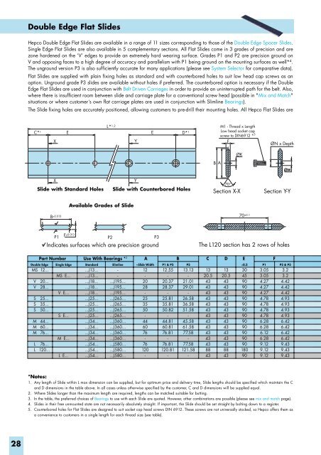
Double Edge Flat Slides<br />
Hepco Double Edge Flat Slides are available in a range of 11 sizes corresponding to those of the Double Edge Spacer Slides.<br />
Single Edge Flat Slides are also available in 5 complementary sections. All Flat Slides come in 3 grades of precision and are<br />
zone hardened on the ‘V’ edges to provide an extremely hard wearing surface. Grades P1 and P2 are precision ground on<br />
V and opposing faces to a high degree of accuracy and parallelism with P1 being ground on the mounting surfaces as well* 4 .<br />
The unground version P3 is also sufficiently accurate for many applications (please see System Selector for comparative data).<br />
Flat Slides are supplied with plain fixing holes as standard and with counterbored holes to suit low head cap screws as an<br />
option. Unground grade P3 slides are available without holes if preferred. The counterbored option is necessary if the Double<br />
Edge Flat Slides are used in conjunction with Belt Driven Carriages in order to provide an uninterrupted path for the belt. Also,<br />
where there is insufficient room between slide and carriage plate for a conventional screw head (possible in "Mix and Match"<br />
situations or where customer’s own flat carriage plates are used in conjunction with Slimline Bearings).<br />
The Slide fixing holes are accurately positioned, allowing customers to pre-drill their mounting holes. All Hepco Flat Slides are<br />
C* 1 E<br />
X<br />
Y<br />
E<br />
D* 1<br />
L* 1,2 Section Y-Y<br />
M1 - Thread x Length<br />
Low head socket cap<br />
screw to DIN6912 * 5<br />
F<br />
ØN x Depth<br />
ØK<br />
B A<br />
ØM<br />
X<br />
Slide with Standard Holes<br />
Y<br />
Slide with Counterbored Holes<br />
70°<br />
Section X-X<br />
Available Grades of Slide<br />
B ±0.013 F ±0.013<br />
P1 P2 P3<br />
Indicates surfaces which are precision ground<br />
The L120 section has 2 rows of holes<br />
70 ±0.1<br />
Part Number Use With Bearings * 3 A B C D E<br />
F<br />
Double Edge<br />
MS<br />
V<br />
V<br />
S<br />
S<br />
S<br />
M<br />
M<br />
M<br />
L<br />
L<br />
12...<br />
20...<br />
28...<br />
25...<br />
35...<br />
50...<br />
44...<br />
60...<br />
76...<br />
76...<br />
120...<br />
Single Edge<br />
MS E...<br />
V E...<br />
S E...<br />
M E...<br />
L E...<br />
Standard<br />
...J13...<br />
...J13...<br />
...J18...<br />
...J18...<br />
...J18...<br />
...J25...<br />
...J25...<br />
...J25...<br />
...J25...<br />
...J34...<br />
...J34...<br />
...J34...<br />
...J34...<br />
...J54...<br />
...J54...<br />
...J54...<br />
Slimline<br />
-<br />
-<br />
...J195...<br />
...J195...<br />
...J195...<br />
...J265...<br />
...J265...<br />
...J265...<br />
...J265...<br />
...J360...<br />
...J360...<br />
...J360...<br />
...J360...<br />
...J580...<br />
...J580...<br />
...J580...<br />
~Slide Width<br />
12<br />
-<br />
20<br />
28<br />
-<br />
25<br />
35<br />
50<br />
-<br />
44<br />
60<br />
76<br />
-<br />
76<br />
120<br />
-<br />
P1 & P2<br />
12.55<br />
-<br />
20.37<br />
28.37<br />
-<br />
25.81<br />
35.81<br />
50.82<br />
-<br />
44.81<br />
60.81<br />
76.81<br />
-<br />
76.81<br />
120.81<br />
-<br />
P3<br />
13.13<br />
-<br />
21.01<br />
29.01<br />
-<br />
26.58<br />
36.58<br />
51.58<br />
-<br />
45.58<br />
61.58<br />
77.58<br />
-<br />
77.58<br />
121.58<br />
-<br />
13<br />
20.5<br />
43<br />
43<br />
43<br />
43<br />
43<br />
43<br />
43<br />
43<br />
43<br />
43<br />
43<br />
43<br />
88<br />
43<br />
13<br />
20.5<br />
43<br />
43<br />
43<br />
43<br />
43<br />
43<br />
43<br />
43<br />
43<br />
43<br />
43<br />
43<br />
88<br />
43<br />
±0.2<br />
30<br />
45<br />
90<br />
90<br />
90<br />
90<br />
90<br />
90<br />
90<br />
90<br />
90<br />
90<br />
90<br />
90<br />
180<br />
90<br />
P1<br />
3.05<br />
3.05<br />
4.27<br />
4.27<br />
4.27<br />
4.78<br />
4.78<br />
4.78<br />
4.78<br />
6.28<br />
6.28<br />
6.12<br />
6.28<br />
9.12<br />
9.12<br />
9.12<br />
P2 & P3<br />
3.2<br />
3.2<br />
4.42<br />
4.42<br />
4.42<br />
4.93<br />
4.93<br />
4.93<br />
4.93<br />
6.42<br />
6.42<br />
6.42<br />
6.42<br />
9.43<br />
9.43<br />
9.43<br />
*Notes:<br />
1. Any length of Slide within L max dimension can be supplied, but for optimum price and delivery time, Slide lengths should be specified which maintain the C<br />
and D dimensions in the table above. In all cases unless otherwise specified by the customer, C and D dimensions will be supplied equal.<br />
2. Where Slides longer than the maximum length are required, lengths can be matched suitable for butting.<br />
3. In the table, the preferred choices of Bearings to use with each Slide are quoted. However, other combinations are possible (please see mix and match page).<br />
4. Slides in their free unmounted state are not necessarily absolutely straight. If important, the Slide should be set straight by bolting down to a register.<br />
5. Counterbored holes for Flat Slides are designed to suit socket cap head screws DIN 6912. These screws are not universally stocked, so Hepco offers them as<br />
a convenience to customers in a single length for each thread size (see table).<br />
28