
You also want an ePaper? Increase the reach of your titles
YUMPU automatically turns print PDFs into web optimized ePapers that Google loves.
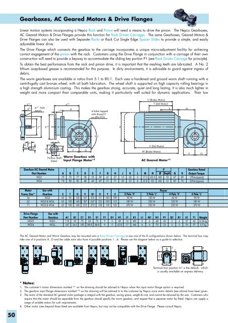
Gearboxes, AC Geared Motors & Drive Flanges<br />
Linear motion systems incorporating a Hepco Rack and Pinion will need a means to drive the pinion. The Hepco Gearboxes,<br />
AC Geared Motors & Drive Flanges provide this function for Rack Driven Carriages. The same Gearboxes, Geared Motors &<br />
Drive Flanges can also be used with Separate Racks or Rack Cut Single Edge Spacer Slides to provide a simple, and easily<br />
adjustable linear drive.<br />
The Drive Flange which connects the gearbox to the carriage incorporates a unique micro-adjustment facility for achieving<br />
correct engagement of the pinion with the rack. Customers using the Drive Flange in conjunction with a carriage of their own<br />
construction will need to provide a keyway to accommodate the sliding key portion P1 (see Rack Driven Carriage for principle).<br />
To obtain the best performance from the rack and pinion drive, it is important that the meshing teeth are lubricated. A No. 2<br />
lithium soap-based grease is recommended for this purpose. In dirty environments, it is advisable to guard against ingress of<br />
debris.<br />
The worm gearboxes are available in ratios from 5:1 to 80:1. Each uses a hardened and ground worm shaft running with a<br />
centrifugally cast bronze wheel, with oil bath lubrication. The wheel shaft is supported on high capacity rolling bearings in<br />
a high strength aluminium casting. This makes the gearbox strong, accurate, quiet and long lasting. It is also much lighter in<br />
weight and more compact than comparable units, making it particularly well suited for dynamic applications. Their low<br />
k* 1 a* 2<br />
g* 1 m* 1 hole<br />
details<br />
c* 2<br />
h* 1 j* 1 b* 2<br />
L<br />
e* 1 f* 1 d* 1<br />
K<br />
M<br />
J<br />
Hollow Shaft<br />
Detail<br />
H<br />
F<br />
G<br />
4 holes tapped<br />
with thread P<br />
on ØN PCD<br />
90°<br />
X<br />
U (Brake Motor)<br />
T (Std Motor)<br />
V (Std Motor)<br />
W (Brake Motor)<br />
Worm Gearbox with<br />
Input Flange Motor* 3 AC Geared Motor* 3<br />
S<br />
H<br />
F<br />
G<br />
Gearbox/AC Geared Motor<br />
Part Number<br />
WG3<br />
WG4<br />
A<br />
72<br />
76<br />
B<br />
75<br />
80<br />
C<br />
77<br />
82<br />
D<br />
38<br />
48<br />
E<br />
33<br />
40<br />
F<br />
39<br />
49<br />
G<br />
41<br />
51<br />
H<br />
57<br />
71<br />
J<br />
15<br />
20<br />
K<br />
25<br />
35<br />
L<br />
5<br />
6<br />
M<br />
17.3<br />
22.8<br />
N<br />
62.5<br />
85<br />
P<br />
Ø Depth<br />
M5 10<br />
M6 12<br />
Q<br />
67<br />
85<br />
R<br />
69<br />
76<br />
Gearbox Rated<br />
Output Torque<br />
17Nm (typical)<br />
32Nm (typical)<br />
Motor<br />
Frame Size* 4<br />
56<br />
63<br />
71<br />
Use with<br />
Gearbox<br />
WG3<br />
WG3 & WG4<br />
WG3 & WG4<br />
S<br />
60<br />
65<br />
65<br />
T<br />
90<br />
100<br />
100<br />
U<br />
130<br />
140<br />
140<br />
V<br />
167<br />
187<br />
212<br />
W<br />
210<br />
247<br />
272<br />
X<br />
111<br />
123<br />
138<br />
Y<br />
100<br />
100<br />
110<br />
Z<br />
109<br />
113<br />
125<br />
2 Pole ‘S’<br />
90 W<br />
180 W<br />
370 W<br />
2 Pole ‘L’<br />
120 W<br />
250 W<br />
550 W<br />
Power<br />
4 Pole ‘S’<br />
60 W<br />
120 W<br />
250 W<br />
4 Pole ‘L’<br />
90 W<br />
180 W<br />
370 W<br />
Drive Flange<br />
Part Number<br />
WGF3<br />
WGF4<br />
Use with<br />
Gearbox<br />
WG3...<br />
WG4...<br />
A1<br />
118<br />
147<br />
B1<br />
35<br />
34.5<br />
C1<br />
75<br />
100<br />
D1<br />
63<br />
88.8<br />
E1<br />
75<br />
88.8<br />
F1<br />
9<br />
9<br />
G1<br />
2<br />
5<br />
H1<br />
49<br />
62.8<br />
J1<br />
14<br />
17<br />
K1<br />
M5<br />
M6<br />
L1<br />
5<br />
6<br />
M1<br />
6<br />
6<br />
N1<br />
48<br />
70<br />
P1<br />
20<br />
25<br />
Q1<br />
2<br />
3<br />
R1<br />
4<br />
5<br />
S1<br />
57<br />
76<br />
T1<br />
43<br />
57<br />
Weight<br />
0.34 kg<br />
0.5 kg<br />
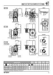
The AC Geared Motor and Worm Gearbox may be mounted onto a Rack Driven Carriage in any one of the 8 configurations shown below. The terminal box may<br />
take one of 4 positions A...D and the cable exits also have 4 possible positions 1...4. Please use the diagram below as a guide to selection.<br />
1 2 3 4 5 6<br />
7<br />
8<br />
1<br />
2<br />
C<br />
B<br />
2 3 4<br />
2<br />
A<br />
3 4<br />
1<br />
1<br />
2 D 1<br />
3 4<br />
Terminal box position A1 is the default, which<br />
is usually available on express delivery.<br />
* Notes:<br />
1. The customer’s motor dimensions marked * 1 on the drawing should be advised to Hepco when the input motor flange option is required.<br />
2. The gearbox input flange dimensions marked * 2 on the drawing will be advised to to the customer by Hepco once motor details (see above) have been given.<br />
3. The motor of the standard AC geared motor package is integral with the gearbox, saving space, weight & cost, and cannot be removed by the user. Customers who<br />
require that the motor should be separable from the gearbox should specify the worm gearbox, and request that a separate motor be fitted. Hepco can supply a<br />
range of suitable motors for such requirements.<br />
4. Other motor sizes beyond those listed are available from Hepco, but may not be compatible with the Drive Flange. Please consult Hepco.<br />
50