
You also want an ePaper? Increase the reach of your titles
YUMPU automatically turns print PDFs into web optimized ePapers that Google loves.
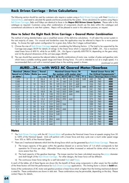
Rack Driven Carriage - Drive Calculations<br />
The following section should be used by customers who require a system using a Rack Driven Carriage with fitted Gearbox or<br />
Geared Motor, and need to calculate the speeds and forces produced by the system. Drive calculations for systems using Hepco<br />
Belt Driven Carriages, Belts and Pulleys are identical to those in the Hepco DLS Driven Linear System. Please refer to this<br />
catalogue as required. Customers using other combinations of components should use the data within this catalogue and<br />
conventional calculations to rate their systems. Hepco will be pleased to assist in this selection process, on request.<br />
How to Select the Right Rack Drive Carriage + Geared Motor Combination<br />
The method of rating detailed below uses a simplified version of the definitive calculations. It will select the correct system in<br />
the vast majority of cases. For unusual and borderline cases the application may be referred to Hepco for a more precise<br />
rating. To choose the right system configuration for a given duty, follow the 3 stages outlined below:<br />
1) Choose the size of Rack Driven Carriage required, considering the following factors: i) The load to be supported by the<br />
Carriage (see pages 58-59 for details of rating); ii) the linear force which is required (an AURD...34... has a maximum<br />
rated linear force of 400 N, while for an AURD...54... this figure is typically 600-700 N, depending on the gear ratio);<br />
and iii) the physical dimensions of the unit (see pages 48-49).<br />
2) The user should then examine the relevant table to identify combinations of motor size, number of poles and gearbox ratio<br />
which have a suitable working speed range and linear driving force. If a unit is intended to run at a single speed, it is<br />
recommended that a unit with a nominal speed close to the working speed is chosen.<br />
(continued on p65)<br />
Nominal<br />
Speed m/s<br />
at 50Hz* 1<br />
1.23<br />
0.88<br />
0.62<br />
0.59<br />
0.51<br />
0.42<br />
0.41<br />
0.35<br />
0.29<br />
0.26<br />
0.25<br />
0.21<br />
0.2<br />
0.16<br />
0.16<br />
0.13<br />
0.12<br />
0.1<br />
0.08<br />
AURD...34... with WG3 AC Geared Motor/Gearbox<br />
Motor<br />
Poles<br />
2<br />
2<br />
2<br />
4<br />
2<br />
4<br />
2<br />
2<br />
4<br />
2<br />
4<br />
2<br />
4<br />
2<br />
4<br />
2<br />
4<br />
4<br />
4<br />
Gear<br />
Ratio<br />
5<br />
7<br />
10<br />
5<br />
12<br />
7<br />
15<br />
18<br />
10<br />
24<br />
12<br />
30<br />
15<br />
38<br />
18<br />
50<br />
24<br />
30<br />
38<br />
Travel<br />
per motor<br />
rev /mm<br />
26.4<br />
18.8<br />
13.2<br />
26.4<br />
11.0<br />
18.8<br />
8.8<br />
7.3<br />
13.2<br />
5.5<br />
11.0<br />
4.4<br />
8.8<br />
3.5<br />
7.3<br />
2.6<br />
5.5<br />
4.4<br />
3.5<br />
56 S<br />
35<br />
61<br />
90<br />
56<br />
112<br />
86<br />
138<br />
168<br />
129<br />
217<br />
155<br />
258<br />
189<br />
323<br />
224<br />
376<br />
284<br />
331<br />
446<br />
Nominal Linear Force /N<br />
for system with motor size* 1<br />
56 L 63 S 63 L 71S<br />
56 99 146 228<br />
91 142 211 322<br />
129 211 301 448<br />
99 138 219 309<br />
159 245 356<br />
142 202 309 446<br />
192 301 446<br />
232 365<br />
206 292 446<br />
298<br />
245 344<br />
352<br />
296 446<br />
440<br />
348<br />
446<br />
71 L<br />
348<br />
446<br />
Rated Linear Force (N)<br />
For Critical Components* 2<br />
Gears<br />
440<br />
498<br />
526<br />
483<br />
541<br />
543<br />
526<br />
511<br />
573<br />
526<br />
588<br />
511<br />
573<br />
529<br />
558<br />
416<br />
573<br />
573<br />
603<br />
Bearings<br />
740<br />
740<br />
740<br />
740<br />
740<br />
740<br />
740<br />
740<br />
740<br />
740<br />
740<br />
740<br />
740<br />
740<br />
740<br />
740<br />
740<br />
740<br />
740<br />
Rack & Pinion<br />
400<br />
400<br />
400<br />
400<br />
400<br />
400<br />
400<br />
400<br />
400<br />
400<br />
400<br />
400<br />
400<br />
400<br />
400<br />
400<br />
400<br />
400<br />
400<br />
64<br />
Notes<br />
* 1 The Rack Driven Carriage with the AC Geared Motor will produce the Nominal Linear Force at speeds ranging from 50<br />
to 120% of the Nominal Speed. Units will perform with a lower force and duty cycle over a much wider speed range<br />
from 10% to 180% of the Nominal Speed.<br />
* 2 There are 3 mechanical elements which limit the driving force which can be generated by a Rack Driven Carriage. These are:<br />
i) The torque capacity of the gears within the gearbox (based on a service factor of 1.4 which corresponds to fast<br />
operation for 8 hours per day). Allowable forces may be either increased or reduced for duties which are less or<br />
more severe than this.<br />
ii) The load capacity of the gearbox bearings. The torque reaction has been calculated assuming the pinion diameter<br />
and shaft length of the Rack Driven Carriage. For other designs, the linear force will be different.<br />
iii) The continuous linear force rating for a well lubricated Rack and Pinion.<br />
In each of the tables, all of these figures are shown (for the benefit of those using components in other ways), but the smallest<br />
of the three factors will limit the performance for Rack Driven Carriage applications. This limiting factor is shown in bold text.<br />
Some of the combinations of AC motor and gearbox produce a linear force which is higher than the limiting mechanical element<br />
is rated for. These combinations are shown in italic text. These combinations may be permissible, depending on the duty. Please<br />
contact Hepco for details.