
Create successful ePaper yourself
Turn your PDF publications into a flip-book with our unique Google optimized e-Paper software.
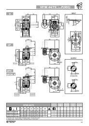
Flange Clamps<br />
Flange Clamps enable the Slide System to act as a self-supporting constructional element of the machine. Manufactured from<br />
aluminium alloy, the clamps are anodised to achieve an attractive and corrosion resistant finish. They are available for use with<br />
all Double Edged Spacer Slides in the S series sizes and larger. Short Flange Clamps (type SFC) enable the Slide to be<br />
supported between two opposing faces. The Long Flange Clamp (type LFC) enables short lengths of Slide to be supported from<br />
one end only. The machined base mounting facility may be utilized by customers wishing to space the Slide System away from<br />
the mounting surface. Deflection of Slides can be determined using data given in the Calculations section.<br />
Assembly<br />
During assembly, care should be taken to ensure that the Flange Clamps are positioned proud of the ends of the Slide* 1 .<br />
Flange fixing screws should be located and slightly tightened, before clamping screws ‘M’ are fully tightened. Progressive<br />
tightening of each screw ‘M’ is recommended. Flange fixing screws may then be fully tightened.<br />
XYZ<br />
+ABC<br />
123<br />
Calculations<br />
P 63<br />
Spacer<br />
Slides<br />
P 24-25<br />
See Application Examples on pages 10 & 14<br />
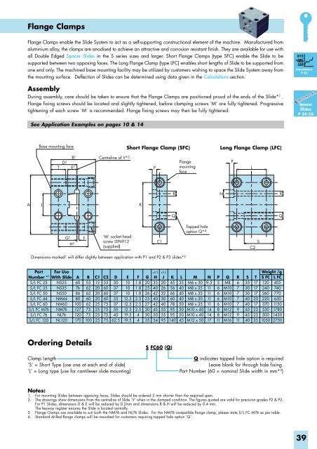
Base mounting face<br />
Short Flange Clamp (SFC)<br />
Long Flange Clamp (LFC)<br />
T<br />
B †<br />
D † E †<br />
Centreline of V* 2<br />
P<br />
Flange<br />
mounting<br />
face<br />
P<br />
L<br />
R<br />
N<br />
R<br />
A<br />
J<br />
K<br />
Q<br />
Q<br />
G † H †<br />
F<br />
‘M’ socket head<br />
screw DIN912<br />
(supplied)<br />
C1<br />
Tapped hole<br />
option Q* 4<br />
S<br />
C2<br />
Dimensions marked † will differ slightly between application with P1 and P2 & P3 slides* 2<br />
Part<br />
Number * 3<br />
S/L FC 25<br />
S/L FC 35<br />
S/L FC 50<br />
S/L FC 44<br />
S/L FC 60<br />
S/L FC M76<br />
S/L FC 76<br />
S/L FC 120<br />
For Use<br />
With Slide<br />
NS25<br />
NS35<br />
NS50<br />
NM44<br />
NM60<br />
NM76<br />
NL76<br />
NL120<br />
A<br />
60<br />
76<br />
86<br />
80<br />
100<br />
127<br />
120<br />
170<br />
B<br />
55<br />
62<br />
62<br />
60<br />
62<br />
75<br />
75<br />
100<br />
C1<br />
15<br />
20<br />
20<br />
20<br />
25<br />
25<br />
25<br />
25<br />
C2<br />
55<br />
60<br />
60<br />
60<br />
75<br />
75<br />
75<br />
75<br />
D<br />
30<br />
37<br />
37<br />
35<br />
37<br />
50<br />
45<br />
62.5<br />
E<br />
10<br />
10<br />
10<br />
12.5<br />
12.5<br />
12.5<br />
19.5<br />
19.5<br />
F<br />
1.8<br />
1.8<br />
1.8<br />
2.5<br />
2.5<br />
2.5<br />
4<br />
4<br />
G<br />
20<br />
25<br />
26<br />
25<br />
27<br />
30<br />
30<br />
35<br />
±0.2 ±0.2<br />
H<br />
35<br />
40<br />
42<br />
40<br />
42<br />
45<br />
50<br />
54<br />
J<br />
20<br />
26<br />
32<br />
30<br />
40<br />
55<br />
55<br />
95<br />
K<br />
45<br />
56<br />
66<br />
60<br />
78<br />
95<br />
95<br />
140<br />
L<br />
35<br />
40<br />
40<br />
40<br />
50<br />
50<br />
50<br />
45<br />
M<br />
M6 x 30<br />
M8 x 35<br />
M8 x 35<br />
M8 x 30<br />
M8 x 35<br />
M10 x 40<br />
M10 x 40<br />
M12 x 50<br />
N<br />
9.5<br />
11<br />
11<br />
11<br />
11<br />
14<br />
14<br />
17<br />
P<br />
5<br />
6<br />
6<br />
6<br />
6<br />
8<br />
8<br />
11<br />
Q<br />
M8<br />
M10<br />
M10<br />
M10<br />
M10<br />
M12<br />
M12<br />
M16<br />
R<br />
6<br />
7<br />
7<br />
7<br />
7<br />
9<br />
9<br />
11<br />
S<br />
35<br />
30<br />
30<br />
40<br />
40<br />
45<br />
45<br />
40<br />
T<br />
17<br />
17<br />
17<br />
20<br />
17<br />
23<br />
23<br />
35<br />
Weight /g<br />
S FC L FC<br />
120 405<br />
240 740<br />
260 770<br />
220 630<br />
370 1150<br />
530 1780<br />
500 1430<br />
1050 2750<br />
Ordering Details<br />
S FC60 (Q)<br />
Clamp Length<br />
‘S’ = Short Type (use one at each end of slide)<br />
‘L’ = Long type (use for cantilever slide mounting)<br />
Q indicates tapped hole option is required<br />
Leave blank for through hole fixing.<br />
Part Number (60 = nominal Slide width in mm* 3 )<br />
Notes:<br />
1. For mounting Slides between opposing faces, Slides should be ordered 2 mm shorter than the required span.<br />
2. The drawings show dimensions from the centreline of Slide ‘V’ when in the clamped condition. The figures quoted are valid for precision grades P2 & P3.<br />
For P1 Slides, dimensions D & E will be reduced by 0.2mm and dimensions B & H will be reduced by 0.4 mm.<br />
The keyway register ensures the Slide is located centrally.<br />
3. Flange Clamps are available to suit both the NM76 and NL76 Slides. For the NM76 compatible flange clamp, please state S/L FC M76 as per table.<br />
4. Standard drilled flange clamps will be reworked for customers requiring tapped hole option ‘Q’.<br />
39