
You also want an ePaper? Increase the reach of your titles
YUMPU automatically turns print PDFs into web optimized ePapers that Google loves.
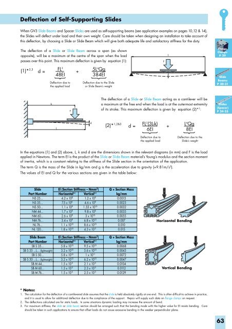
Deflection of Self-Supporting Slides<br />
When <strong>GV3</strong> Slide Beams and Spacer Slides are used as self-supporting beams (see application examples on pages 10,12 & 14),<br />
the Slides will deflect under load and their own weight. Care should be taken when designing an installation to take account of<br />
this deflection, by choosing a Slide or Slide Beam which will give both adequate life and satisfactory stiffness for the duty.<br />
The deflection of a Slide or Slide Beam across a span (as shown<br />
opposite), will be a maximum at the centre of the span when the load<br />
passes over this point. This maximum deflection is given by equation (1):<br />
F<br />
L<br />
Flange<br />
Clamps<br />
P 39<br />
(1)* 2,3 d =<br />
FL 3<br />
+<br />
5L4 Qg<br />
48EI<br />
384EI<br />
Deflection due to<br />
the applied load<br />
Deflection due to the Slide<br />
or Slide Beam’s weight<br />
d<br />
Slide<br />
Beams<br />
P 30-31<br />
k<br />
F<br />
The deflection of a Slide or Slide Beam acting as a cantilever will be<br />
a maximum at the free end when the load is at the outermost extremity<br />
of its stroke. This maximum deflection is given by equation (2)* 1 :<br />
Slides<br />
(Spacer)<br />
P 24-25<br />
L<br />
d<br />
(2)* 1,2&3 d =<br />
FL 2 (3L-k)<br />
+<br />
L4 Qg<br />
6EI<br />
8EI<br />
Deflection due to<br />
the applied load<br />
Deflection due to the<br />
Slide’s weight<br />
In the equations (1) and (2) above, L, k and d are the dimensions shown in the relevant diagrams (in mm) and F is the load<br />
applied in Newtons. The term EI is the product of the Slide or Slide Beam material’s Young’s modulus and the section moment<br />
of inertia, which is a constant relating to the stiffness of the Slide section in the orientation of the application.<br />
The term Q is the mass of the Slide in kg/mm and g is the acceleration due to gravity (=9.81m/s 2 ).<br />
The values of EI and Q for the various sections are given in the table below:<br />
Slide<br />
Part Number<br />
NS 25...<br />
NS 35...<br />
NS 50...<br />
NM 44...<br />
NM 60...<br />
NM 76...<br />
NL 76...<br />
NL 120...<br />
El (Section Stiffness – Nmm 2 )<br />
Horizontal* 3 Vertical* 3<br />
4.2 x 10 8 1.2 x 10 9<br />
7.5 x 10 8 4.6 x 10 9<br />
1.1 x 10 9 1.55 x 10 10<br />
1.7 x 10 9 9.8 x 10 9<br />
2.6 x 10 9 3 x 10 10<br />
3.4 x 10 9 6.8 x 10 10<br />
1.1 x 10 10 8.6 x 10 10<br />
1.8 x 10 10 4.3 x 10 11<br />
Q = Section Mass<br />
kg/mm<br />
0.0015<br />
0.0023<br />
0.0032<br />
0.0035<br />
0.0055<br />
0.007<br />
0.010<br />
0.015<br />
Horizontal Bending<br />
Slide Beam<br />
Part Number<br />
SB S 35...<br />
SB S 35 ...L... (lightweight)<br />
SB S 50...<br />
SB S 50 ...L... (lightweight)<br />
SB M 44...<br />
SB M 60...<br />
SB M 76...<br />
El (Section Stiffness – Nmm 2 )<br />
Horizontal* 3 Vertical* 3<br />
5.8 x 10 10 9.5 x 10 10<br />
3.2 x 10 10 5.6 x 10 10<br />
5.8 x 10 10 1 x 10 11<br />
3.2 x 10 10 6.2 x 10 10<br />
1.5 x 10 11 2.1 x 10 11<br />
1.5 x 10 11 2.3 x 10 11<br />
1.5 x 10 11 2.5 x 10 11<br />
Q = Section Mass<br />
kg/mm<br />
0.0068<br />
0.0043<br />
0.0072<br />
0.0047<br />
0.0104<br />
0.0112<br />
0.0129<br />
Vertical Bending<br />
* Notes:<br />
1. The calculation for the deflection of a cantilevered slide assumes that the slide is held absolutely rigidly at one end. This is often difficult to achieve in practice,<br />
and it is usual to allow for additional deflection due to the compliance of the support. Hepco will supply such data on flange clamps on request.<br />
2. The deflections calculated are for static loads. In some situations dynamic loading may increase the amount of bend.<br />
3. For maximum stiffness, the slide or slide beam section should be arranged such that the bending mode with the higher value for EI resists bending. Care<br />
should be taken in such applications to ensure that offset loads do not cause excessive bending in the weaker perpendicular plane.<br />
63