
Create successful ePaper yourself
Turn your PDF publications into a flip-book with our unique Google optimized e-Paper software.
Rack Driven Carriage - Drive Calculations<br />
3) In many cases, there will be more than one combination which will satisfy the speed and force requirements. In these<br />
cases, the following secondary factors may be considered:<br />
i) For arduous applications, it it best to select the combination with the highest rated linear force for the gears.<br />
ii) For gearbox ratios of less than 29:1, the motor can be back-driven through the gearbox. This may be useful as<br />
it will allow the axis to be manually positioned with the power switched off. In some cases, however (for instance<br />
in lifting applications) back-driving may be undesirable. If this is the case, specify the electro-magnetic brake<br />
option or a select a higher gearbox ratio.<br />
iii) Two pole motors will be lighter than four pole for a given power.<br />
iv) For best dynamic performance, use a four pole motor. This will give sharper acceleration and more dynamic<br />
performance than a two pole motor driving through a gearbox with a higher ratio. For a given load, a more<br />
Gearboxes<br />
- F c<br />
P r<br />
& Geared<br />
powerful motor will generally accelerate the system more quickly than a less powerful one, but the benefit of<br />
Motors<br />
P50-51<br />
increasing power will be small if loads are light.<br />
v) Four pole motors keep the speed in the gearbox down, minimising heating and maximising life.<br />
vi) The marginal cost of extra motor power is low on an AC system. If in doubt between two sizes it is often best<br />
to specify larger, as there will usually be only a small extra cost.<br />
Pinions<br />
P 45<br />
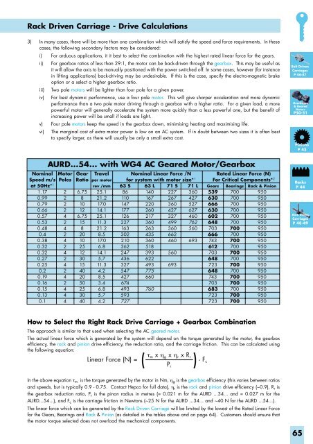
AURD...54... with WG4 AC Geared Motor/Gearbox<br />
Nominal Motor Gear Travel Nominal Linear Force /N<br />
Rated Linear Force (N)<br />
Speed m/s Poles Ratio per motor for system with motor size* 1 For Critical Components* 2<br />
at 50Hz* 1<br />
Racks<br />
rev /mm 63 S 63 L 71 S 71 L Gears Bearings Rack & Pinion<br />
P 44<br />
1.17<br />
0.99<br />
0.79<br />
0.66<br />
2<br />
2<br />
2<br />
2<br />
6.75<br />
8<br />
10<br />
12<br />
25.1<br />
21.2<br />
17.0<br />
14.1<br />
86<br />
110<br />
147<br />
177<br />
140<br />
167<br />
220<br />
260<br />
227<br />
267<br />
360<br />
427<br />
360<br />
427<br />
527<br />
627<br />
539<br />
630<br />
666<br />
630<br />
700<br />
700<br />
700<br />
700<br />
950<br />
950<br />
950<br />
950<br />
Rack Driven<br />
0.57 4 6.75 25.1 126 217 327 460 602 700 950<br />
Carriages<br />
0.53 2 15 11.3 227 360 499 762 648 700 950<br />
P 48-49<br />
0.48<br />
0.4<br />
0.38<br />
0.32<br />
0.32<br />
0.27<br />
0.25<br />
0.2<br />
0.19<br />
0.16<br />
0.15<br />
0.13<br />
0.1<br />
4<br />
2<br />
4<br />
2<br />
4<br />
2<br />
4<br />
2<br />
4<br />
2<br />
4<br />
4<br />
4<br />
8<br />
20<br />
10<br />
25<br />
12<br />
30<br />
15<br />
40<br />
20<br />
50<br />
25<br />
30<br />
40<br />
21.2<br />
8.5<br />
17.0<br />
6.8<br />
14.1<br />
5.7<br />
11.3<br />
4.2<br />
8.5<br />
3.4<br />
6.8<br />
5.7<br />
4.2<br />
163<br />
302<br />
210<br />
362<br />
247<br />
436<br />
327<br />
547<br />
427<br />
674<br />
493<br />
593<br />
727<br />
263<br />
435<br />
360<br />
518<br />
393<br />
622<br />
493<br />
775<br />
660<br />
760<br />
360<br />
662<br />
460<br />
560<br />
693<br />
560<br />
693<br />
703<br />
666<br />
743<br />
612<br />
703<br />
648<br />
723<br />
648<br />
743<br />
703<br />
683<br />
723<br />
723<br />
700<br />
700<br />
700<br />
700<br />
700<br />
700<br />
700<br />
700<br />
700<br />
700<br />
700<br />
700<br />
700<br />
950<br />
950<br />
950<br />
950<br />
950<br />
950<br />
950<br />
950<br />
950<br />
950<br />
950<br />
950<br />
950<br />
How to Select the Right Rack Drive Carriage + Gearbox Combination<br />
The approach is similar to that used when selecting the AC geared motor.<br />
The actual linear force which is generated by the system will depend on the torque generated by the motor, the gearbox<br />
efficiency, the rack and pinion drive efficiency, the reduction ratio, and the carriage friction. This can be calculated using<br />
the following equation:<br />
τ<br />
Linear Force (N) =<br />
(<br />
m x η g x η r x R r<br />
)<br />
Belt Driven<br />
Carriages<br />
P 46-47<br />
In the above equation τ m is the torque generated by the motor in Nm, η g is the gearbox efficiency (this varies between ratios<br />
and speeds, but is typically 0.9 - 0.75. Contact Hepco for full data), η r is the rack and pinion drive efficiency (~0.9), R r is<br />
the gearbox reduction ratio, P r is the pinon radius in metres (= 0.021 m for the AURD ...34... and = 0.027 m for the<br />
AURD...54...), and F c is the carriage friction in Newtons (~25 N for the AURD ...34... and ~40 N for the AURD ...54...).<br />
The linear force which can be generated by the Rack Driven Carriage will be limited by the lowest of the Rated Linear Force<br />
for the Gears, Bearings and Rack & Pinion (as detailed in the tables above and on page 64). Customers should ensure that<br />
the motor torque selected does not overload the mechanical components.<br />
65