
Create successful ePaper yourself
Turn your PDF publications into a flip-book with our unique Google optimized e-Paper software.
Load/Life Calculations<br />
Individual ‘V’ Bearing Calculations<br />
Many systems do not use a standard 4 bearing carriage. In such cases it is<br />
necessary to use conventional statics calculations to determine the loading on each<br />
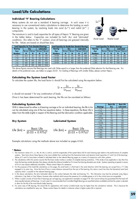
bearing in the system, by resolving loads into axial (LA* 1 ) and radial (LR* 1 )<br />
components.<br />
The maximum LA and LR load capacities for all types of Hepco ‘V’ Bearing are given<br />
in the tables below. Capacities are included for both ‘dry’ and ‘lubricated’<br />
conditions - this refers to the ‘V’ contact, since all bearings are greased internally<br />
for life. Values are based on shock-free duty.<br />
LA* 3<br />
LR<br />
Axial Load<br />
Radial Load<br />
Load Capacities for Twin Standard Bearings<br />
Bearing<br />
Dry<br />
Lubricated<br />
Part<br />
Numbers<br />
...J 13...<br />
...J 18...<br />
...J 25...<br />
...J 34...<br />
...J 54...<br />
LA (max)<br />
N<br />
22.5<br />
45<br />
100<br />
200<br />
450<br />
LR (max)<br />
N<br />
45<br />
90<br />
200<br />
400<br />
900<br />
LA (max)<br />
N<br />
60<br />
125<br />
320<br />
800<br />
1800<br />
LR (max)<br />
N<br />
120<br />
200<br />
600<br />
1400<br />
3200<br />
Load Capacities for Double Row Standard Bearings<br />
Bearing<br />
Dry<br />
Lubricated<br />
Part<br />
Numbers<br />
...J 18 DR...<br />
...J 25 DR...<br />
...J 34 DR...<br />
...J 54 DR...<br />
LA (max)<br />
N<br />
45<br />
100<br />
200<br />
450<br />
LR (max)<br />
N<br />
90<br />
200<br />
400<br />
900<br />
LA (max)<br />
N<br />
190<br />
400<br />
900<br />
2500<br />
LR (max)<br />
N* 6<br />
600<br />
1500<br />
3000<br />
5000<br />
Bearing<br />
Part<br />
Numbers<br />
...J 195...<br />
...J 265...<br />
...J 360...<br />
...J 580...<br />
Load Capacities for Slimline Bearings<br />
Dry<br />
Lubricated<br />
The above figures assume that Bearings are used with Slides equal to or larger than the preferred Slide selection for that Bearing size. For<br />
details of the preferred sizes, see tables on pages 32-35. For loading of Bearings with smaller Slides, please contact Hepco.<br />
LA (max)<br />
N<br />
45<br />
100<br />
200<br />
450<br />
LR (max)<br />
N<br />
90<br />
200<br />
400<br />
900<br />
LA (max)<br />
N<br />
100<br />
235<br />
500<br />
1060<br />
LR (max)<br />
N<br />
240<br />
575<br />
1200<br />
2600<br />
Calculating the System Load Factor<br />
To calculate the system life, the load factor LF should first be calculated using the equation below.<br />
LA<br />
LF = +<br />
LA (max)<br />
LR<br />
LR (max)<br />
LF should not exceed 1 for any combination of loads.<br />
Once LF has been determined for each bearing, the life can be caculated as follows:<br />
Calculating System Life<br />
With LF determined for either a 4 bearing carriage or for an individual bearing, the life in km<br />
can be calculated using one of the two equations below. In these equations, the Basic Life is<br />
taken from the table (right) in respect of the Bearing and the lubrication condition applicable.<br />
Dry System<br />
Life (km) =<br />
Lubricated System<br />
Basic Life<br />
Basic Life<br />
Life (km) =<br />
(0.03 + 0.97LF) 2 (0.03 + 0.97LF) 3<br />
Bearings<br />
...J 13...<br />
...J 18...<br />
...J 18 DR...<br />
...J 25...<br />
...J 25 DR...<br />
...J 34...<br />
...J 34 DR...<br />
...J 54...<br />
...J 54 DR...<br />
...J 195...<br />
...J 265...<br />
...J 360...<br />
...J 580...<br />
Basic Life<br />
Dry<br />
40<br />
50<br />
50<br />
70<br />
70<br />
100<br />
100<br />
150<br />
150<br />
50<br />
70<br />
100<br />
150<br />
Basic Life<br />
Lubricated<br />
50<br />
100<br />
100<br />
50<br />
70<br />
100<br />
250<br />
250<br />
500<br />
100<br />
50<br />
250<br />
200<br />
Example calculations using the methods above are included on pages 61-62.<br />
* Notes:<br />
1. The maximum values of L1, L2, Ms, M, Mv, LA and LR, and the magnitudes of the system Basic Life for each bearing type relate to the performance of complete<br />
systems. Tests have shown these figures to be more reliable than working from the theoretical static and dynamic load capacities ( C and Co) of the bearings.<br />
Values of C and Co have been included in tabulated data on the relevant Bearing pages as a means of comparison with other systems.<br />
2. The calculations within this section assume that the linear stroke involves a number of complete bearing revolutions. If the stroke of any application is less than five<br />
times the bearing outside diameter, then please calculate the distance travelled as if it moves five bearing diameters per stroke. Systems operating at speeds in excess<br />
of 8 m/s may require additional calculation. Please contact Hepco for assistance.<br />
3. For the purposes of the load/Life calculations on this page, the axial load LA is that load in the axial direction which the bearing can accept from a ‘V’ slide<br />
engaged in its outer ring. Since the line of force is some distance removed from the axis of the bearing, this value is much less than the theoretical axial load<br />
capacity which is quoted on the relevant bearing page.<br />
4. In the above calculations, the term lubricated refers to the contact between the slide and bearing ‘V’s. This lubrication may best be achieved using Hepco<br />
Lubricators, Cap Seals or Cap Wipers, however other methods which ensure the presence of a suitable grease or oil in the critical area are acceptable.<br />
5. When a system consists of more than 4 bearings per carriage (e.g. see application axamples on pages 9 & 14) it cannot always be guaranteed that the load will<br />
share equally between all bearings. In such cases it is recommended that Controlled Height Bearings are specified (where available) and that the system is derated<br />
to allow for the life of the most heavily laden bearing.<br />
6. For some sizes of DR bearing, the actual life for applications with mainly L2/radial loads may be higher than the calculations indicate. This is because the<br />
calculations are simplified for easy use. Please contact Hepco for details in instances where a higher system life is required.<br />
59