
You also want an ePaper? Increase the reach of your titles
YUMPU automatically turns print PDFs into web optimized ePapers that Google loves.
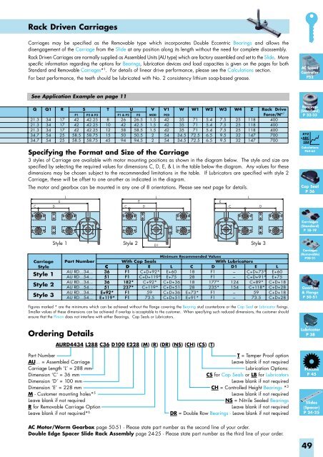
Rack Driven Carriages<br />
Carriages may be specified as the Removable type which incorporates Double Eccentric Bearings and allows the<br />
disengagement of the Carriage from the Slide at any position along its length without the need for complete disassembly.<br />
Rack Driven Carriages are normally supplied as Assembled Units (AU type) which are factory assembled and set to the Slide. More<br />
specific information regarding the options for Bearings, lubrication devices and load capacities is given on the pages for both<br />
Standard and Removable Carriages* 1 . For details of linear drive performance, please see the Calculations section.<br />
For best performance, the teeth should be lubricated with No. 2 consistency lithium soap-based grease.<br />
AC Speed<br />
Controller<br />
P52<br />
See Application Example on page 11<br />
Q<br />
21.3<br />
21.3<br />
21.3<br />
34.7<br />
34.7<br />
C<br />
Q1<br />
34<br />
34<br />
34<br />
54<br />
54<br />
D<br />
E<br />
R<br />
17<br />
17<br />
17<br />
25<br />
25<br />
L<br />
P1<br />
42<br />
42<br />
42<br />
58.5<br />
58.5<br />
S<br />
P2 & P3<br />
42.25<br />
42.25<br />
42.25<br />
58.75<br />
58.75<br />
T<br />
8<br />
10<br />
12<br />
15<br />
45<br />
P1 & P2<br />
26<br />
42<br />
58<br />
50<br />
94<br />
C<br />
U<br />
P3<br />
26.5<br />
42.5<br />
58.5<br />
50.5<br />
94.5<br />
E<br />
D<br />
V<br />
MOD<br />
1.5<br />
1.5<br />
1.5<br />
2<br />
2<br />
L<br />
V1<br />
PCD<br />
42<br />
42<br />
42<br />
54<br />
54<br />
W<br />
35<br />
35<br />
35<br />
34.5<br />
34.5<br />
W1<br />
71<br />
71<br />
71<br />
72.5<br />
72.5<br />
W2<br />
5.4<br />
5.4<br />
5.4<br />
6.5<br />
6.5<br />
W3<br />
7.5<br />
7.5<br />
7.5<br />
9.5<br />
9.5<br />
E<br />
C<br />
W4<br />
25<br />
25<br />
25<br />
32<br />
32<br />
L<br />
Z<br />
118<br />
118<br />
118<br />
147<br />
147<br />
D<br />
Rack Drive<br />
Force/N* 7<br />
400<br />
400<br />
400<br />
700<br />
700<br />
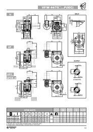
Specifying the Format and Size of the Carriage<br />
3 styles of Carriage are available with motor mounting positions as shown in the diagram below. The style and size are<br />
specified by selecting the required values for dimensions C, D, E, & L in the table below the diagram. Any values for these<br />
dimensions may be chosen subject to the recommended limitations in the table. If Lubricators are specified with style 2<br />
Carriage, these will be offset to one another as indicated in the diagram.<br />
The motor and gearbox can be mounted in any one of 8 orientations. Please see next page for details.<br />
Bearings<br />
(Standard)<br />
P 32-33<br />
XYZ<br />
+ABC<br />
123<br />
Calculations<br />
P64-65<br />
Cap Seal<br />
P 36<br />
Carriages<br />
(Standard)<br />
P 18-19<br />
Carriage<br />
Style<br />
Style 1<br />
Style 2<br />
Style 3<br />
Style 1 Style 2<br />
Style 3<br />
Part Number<br />
AU RD...34...<br />
AU RD...54...<br />
AU RD...34...<br />
AU RD...54...<br />
AU RD...34...<br />
AU RD...54...<br />
C<br />
36<br />
51<br />
36<br />
51<br />
E+92*<br />
E+119*<br />
D1<br />
With Cap Seals<br />
D E<br />
F1 C+D+92*<br />
F1 C+D+119*<br />
182* C+92*<br />
237* C+119*<br />
F1 59<br />
F1 73.5<br />
Minimum Recommended Values<br />
With Lubricators<br />
L<br />
E+60<br />
E+75<br />
C+D+36<br />
C+D+51<br />
C+D+36<br />
C+D+51<br />
C<br />
18<br />
28<br />
18<br />
28<br />
E+73*<br />
E+91*<br />
D<br />
F1<br />
F1<br />
177*<br />
235*<br />
F1<br />
F1<br />
D1<br />
–<br />
–<br />
124<br />
154<br />
–<br />
–<br />
E<br />
C+D+73*<br />
C+D+91*<br />
C+89*<br />
C+118*<br />
59<br />
73.5<br />
L<br />
E+60<br />
E+75<br />
C+D+18<br />
C+D+28<br />
C+D+18<br />
C+D+28<br />
Carriages<br />
(Removable)<br />
P20-21<br />
Gearbox<br />
& Flange<br />
P 50-51<br />
Figures marked * are the minimums which can be achieved without the flange covering the Bearing stud counterbore or the Cap Seal or Lubricator fixings.<br />
Smaller values of these dimensions can be achieved if overlap is acceptable to the customer. When specifying such reduced dimensions, the customer should<br />
ensure that the Pinion does not interfere with either Bearings, Cap Seals or Lubricators.<br />
Ordering Details<br />
Lubricator<br />
P 38<br />
AURD4434 L288 C36 D100 E228 (M) (R) (DR) (NS) (CH) (CS) (T)<br />
Part Number<br />
AU... = Assembled Carriage<br />
Carriage Length ‘L’ = 288 mm<br />
Dimension ‘C’ = 36 mm<br />
Dimension ‘D’ = 100 mm<br />
Dimension ‘E’ = 228 mm<br />
M - Customer mounting holes* 5<br />
Leave blank if not required<br />
R for Removable Carriage Option<br />
Leave blank if not required* 6<br />
T = Tamper Proof option<br />
Leave blank if not required<br />
Lubrication Options:<br />
CS for Cap Seals or LB for Lubricators<br />
Leave blank if not required<br />
CH = Controlled Height Bearings * 3<br />
Leave blank if not required<br />
NS = Nitrile Sealed Bearings<br />
Leave blank if not required<br />
DR = Double Row Bearings - Leave blank if not required<br />
Pinions<br />
P 45<br />
Slides<br />
(Spacer)<br />
P 24-25<br />
AC Motor/Worm Gearbox page 50-51 - Please state part number as the second line of your order.<br />
Double Edge Spacer Slide Rack Assembly page 24-25 - Please state part number as the third line of your order.<br />
49