GM-TTT - Alpermann+Velte
GM-TTT - Alpermann+Velte
GM-TTT - Alpermann+Velte

You also want an ePaper? Increase the reach of your titles
YUMPU automatically turns print PDFs into web optimized ePapers that Google loves.
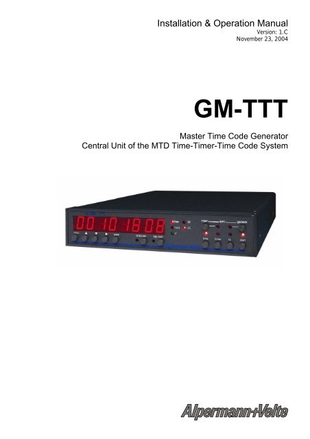
Installation & Operation Manual<br />
Version: 1.C<br />
November 23, 2004<br />
<strong>GM</strong>-<strong>TTT</strong><br />
Master Time Code Generator<br />
Central Unit of the MTD Time-Timer-Time Code System
Installation & Operation Manual <strong>GM</strong>-<strong>TTT</strong><br />
Page 1<br />
CONTENTS<br />
A1<br />
A2<br />
A3<br />
A4<br />
A5<br />
A6<br />
REVISION HISTORY<br />
COPYRIGHT<br />
WARRANTY<br />
UNPACKING/SHIPPING/REPACKAGING INFORMATION<br />
SAFETY INSTRUCTIONS<br />
CERTIFICATIONS & COMPLIANCES<br />
1 INTRODUCTION TO THE <strong>GM</strong>-<strong>TTT</strong> 10<br />
1.1 OVERVIEW 10<br />
1.2 OPTIONAL MODULES 11<br />
1.3 APPLICATION DIAGRAMS 12<br />
1.4 CONNECTIONS AT THE REAR AND TECHNICAL DATA 13<br />
1.5 FUNCTIONS OF BUTTONS, OVERVIEW 16<br />
1.6 STATUS INDICATION BY LED’S, OVERVIEW 17<br />
1.7 THE MENU STRUCTURE, OVERVIEW 19<br />
1.8 AFTER POWER-ON 21<br />
2 MAIN OPERATING MODES 23<br />
2.1 FUNDAMENTAL PRINCIPLES 23<br />
2.2 TIME OPERATING MODE 24<br />
2.3 TIMER OPERATING MODE 25<br />
2.4 TC OPERATING MODE 26<br />
2.5 START OPERATING MODE 28<br />
3 DETAILED MENU DESCRIPTION 29<br />
3.1 GENERAL DESCRIPTION 29<br />
3.2 SET 29<br />
3.2.1 SET START: Enter a Start Value 29<br />
3.2.2 SET USER: Enter User Defined Data for the Binary Groups 30<br />
3.2.3 SET TIME: Set the Time of the Internal Clock 30<br />
3.2.4 SET DATE: Set the Date of the Internal Clock 30<br />
3.2.5 USER MOD.: Data Content of the Binary Groups 31<br />
3.2.6 LOCK: Genlock and Colour Lock Mode 34<br />
3.2.7 F-RATE: Select Frame Rate and Television System 34<br />
3.2.8 PARA: More System Parameters 35<br />
3.2.9 FACTORY: Factory Reset 35<br />
3.3 TIMER 36<br />
3.3.1 TIME A-F: Installation of the Timer Operating Mode 36<br />
3.3.2 U STORE / U LOAD / U RESET 38<br />
3.3.3 A ... F: Display Timer A ... F 38<br />
3.4 LTC 39<br />
3.4.1 OUT: LTC Output Level 39<br />
3.4.2 POLARITY: Select the Use of the Polarity Bit 39<br />
3.4.3 1: Display the LTC Flag Bits 40
Installation & Operation Manual <strong>GM</strong>-<strong>TTT</strong><br />
Page 2<br />
3.5 VITC 41<br />
3.6 STATUS 42<br />
3.7 TEST 43<br />
3.8 REFERENCE 44<br />
3.8.1 MODE 1: Automatic Setting and DST Mode of the Internal Clock 44<br />
3.8.2 MODE 2: Time for Automatic Setting of the Internal Clock 46<br />
3.8.3 1 ... 6: Status Data of the Reference Time 47<br />
3.9 SERIAL 49<br />
3.9.1 FORMAT: Select the Baud Rate and Format of the Serial Interface 49<br />
3.9.2 PROTOCOL: Select the Remote Control Protocol 49<br />
3.10 LTC IN 50<br />
3.10.1 MODE: Settings for the Operation Mode Using External LTC 50<br />
3.10.2 OFFSET: Offset Programming for the Time Information 51<br />
3.10.3 1 ... 3: Status Data of the Readout LTC 51<br />
3.11 GPI 52<br />
3.11.1 SET TIME: Pre-set the Comparative Time Value for Relay Switching 52<br />
3.11.2 SET MODE: Set the GPI Mode 52<br />
3.12 ZONE 53<br />
3.12.1 OFFS 1: Time Zone Offset During Normal Time 54<br />
3.12.2 OFFS 2: Time Zone Offset During Daylight Saving Time (DST) 54<br />
3.12.3 DST on: Program the Beginning of the Daylight Saving Time 55<br />
3.12.4 DST off: Program the End of the Daylight Saving Time 55<br />
3.12.5 DST Period: Indicate Beginning and End of DST of the Current Year 56<br />
3.12.6 RESET A - F: Reset the Parameters of the Time Zones for Timer A - F 56<br />
4 GENLOCK 57<br />
4.1 GENLOCK TO A BLACK-BURST OR VIDEO SIGNAL 57<br />
4.2 GENLOCK TO A LTC SOURCE 58<br />
4.3 GENLOCK TO A 1PPS SIGNAL 59<br />
5 OPERATION WITH A REAL TIME REFERENCE 60<br />
5.1 CONNECTION OF AN EXTERNAL REFERENCE 60<br />
5.2 DCF IN OPTION: INSTALLATION OF A DCF77 RECEIVER 61<br />
5.3 GPS IN OPTION: INSTALLATION OF A GPS RECEIVER 62<br />
5.4 OPTION T: BATTERY-BUFFERED CLOCK MODULE 64<br />
5.5 TIME TRANSFER DURING NORMAL OPERATION AND TIME JUMPS 65<br />
5.6 INTERNAL CLOCK, AUTOMATIC DST MODE, BINARY GROUPS WITH DATE<br />
AND STATUS 67<br />
5.7 REAL TIME COUPLING OF TIME CODE AND VIDEO 68<br />
6 FURTHER DETAILS 70<br />
6.1 FACTORY SETTINGS 70<br />
6.2 MAINTENANCE 72<br />
7 OPTIONAL MODULES AND FUNCTIONS 73<br />
7.1 COLOUR LOCK 73<br />
7.2 VITC GENERATOR 74<br />
7.3 SERIAL REMOTE CONTROL INTERFACE 75<br />
7.3.1 General 75<br />
7.3.2 Commands 76
Installation & Operation Manual <strong>GM</strong>-<strong>TTT</strong><br />
7.4 REFERENCE TIME INPUT VIA EXTERNAL LTC 78<br />
7.4.1 General 78<br />
7.4.2 Accepting Time, Date and Status Information of the External LTC 78<br />
7.4.3 Examples 79<br />
7.5 SECONDS AND MINUTES PULSE OUTPUT 81<br />
7.6 ANALOGUE MASTER OUTPUT 82<br />
Page 3
Installation & Operation Manual <strong>GM</strong>-<strong>TTT</strong><br />
Page 4<br />
A1 Revision History<br />
No. Date Subject<br />
0.x September 10, 2002 Preliminary IBC-2002 document, supplementary data may be published soon.<br />
1.0 October 31, 2002<br />
1.1 November 04, 2002 Headlines 3.12.1 and 3.12.2 exchanged.<br />
Diagram of chapter “6.2 Maintenance” revised.<br />
Some editorial changes.<br />
1.2 March 18, 2003 Extension of USER MODE: “A DATE-7”.<br />
Chapter 7.4: Reference Time Input via External LTC.<br />
1.3 March 28, 2003 Correction at USER MODE: “A DATE-7”: appointment code must be $8 instead of $1.<br />
1.4 May 07, 2003 Correction chap. 1.4, pinning GPI: COM1 = pin 6 (not pin 3).<br />
1.5 June 10, 2003 Extension of USER MODE: “b OFF”.<br />
1.6 June 30, 2003 Option “2“ (RS232) and Option “4“ (RS422): add pinning of DSUB9 at chap. 1.4.<br />
Chapter 7.3.1: additional note: because of the missing RS485 interface to the control<br />
units of the MTD system, <strong>GM</strong>-<strong>TTT</strong> can no longer work as a central unit of this system.<br />
1.7 July 08, 2003 Option “P“: addenda at chapters 1.2 and 1.4, new chapter 7.5.<br />
1.8 August 22, 2003 Extension of GPI feature, chapter 3.11: timer time to trigger can be C, D, E or F as<br />
well.<br />
1.9 November 20, 2003 Range of VITC lines changed, chapter 3.5 and 7.2.<br />
Editorial changes at chapter 3.12.3 and 3.12.4.<br />
1.A December 08, 2003 Option “A“: addenda at chapters 1.2 and 1.4, new chapter 7.6.<br />
1.B February 05, 2004 New submenu “PARA”: main operating mode start programmable.<br />
1.C November 23, 2004 Chapter 3.2.5: new formats of setting the date in the binary groups.<br />
A2<br />
Copyright<br />
Copyright © <strong>Alpermann+Velte</strong> Electronic Engineering GmbH 2002. All rights reserved. No<br />
part of this publication may be reproduced, translated into another language, stored in a<br />
retrieval system, or transmitted, in any form or by any means, electronic, mechanical,<br />
photocopying, recording, or otherwise without the prior written consent of <strong>Alpermann+Velte</strong><br />
Electronic Engineering GmbH.<br />
Printed in Germany.<br />
Technical changes are reserved.<br />
All brand and product names mentioned herein are used for identification purposes only, and<br />
are trademarks or registered trademarks of their respective holders.<br />
Information in this publication replaces all previously published information. <strong>Alpermann+Velte</strong><br />
Electronic Engineering GmbH assumes no responsibility for errors or omissions. Neither is any<br />
liability assumed for damages resulting from the use of the information contained herein.<br />
For further information please contact your local dealer or:<br />
<strong>Alpermann+Velte</strong><br />
Electronic Engineering GmbH<br />
Otto-Hahn-Str. 42<br />
D-42369 Wuppertal<br />
Phone: ++49 - (0)202 – 244 111 0<br />
Fax: ++49 - (0)202 – 244 111 5<br />
E-Mail: info@alpermann-velte.com<br />
Internet: http://www.alpermann-velte.com
Installation & Operation Manual <strong>GM</strong>-<strong>TTT</strong><br />
Page 5<br />
A3 Warranty<br />
<strong>Alpermann+Velte</strong> warrants that their products will be free from defects in materials and<br />
workmanship for a period of two years from the date of shipment. If this product proves<br />
defective during the warranty period, <strong>Alpermann+Velte</strong>, at its option, will repair or replace the<br />
defective product without charge, provided this product are returned to <strong>Alpermann+Velte</strong><br />
freight prepaid.<br />
In order to obtain service under this warranty, Customer must notify <strong>Alpermann+Velte</strong> of the<br />
defect before expiration of the warranty period and make suitable arrangements for the<br />
performance of service. Customer shall be responsible for packaging and shipping the<br />
defective product to <strong>Alpermann+Velte</strong>, please notice the Shipping Information given below.<br />
This warranty shall not apply to any defect, failure or damage caused by abuse, misuse,<br />
improper use, negligence, accident, modification, alteration, or improper or inadequate<br />
maintenance and care.<br />
This warranty is given by <strong>Alpermann+Velte</strong> with respect to this product in lieu of any other<br />
warranties, express or implied. <strong>Alpermann+Velte</strong> and its vendors disclaim any implied<br />
warranties of merchantability or fitness for a particular purpose. <strong>Alpermann+Velte</strong>’s responsibility<br />
to repair or replace defective products is the sole and exclusive remedy provided to the<br />
customer for breach of this warranty. <strong>Alpermann+Velte</strong> and its vendors will not be liable for<br />
any indirect, special, incidental, or consequential damages irrespective of whether<br />
<strong>Alpermann+Velte</strong> or the vendor has advance notice of the possibility of such damages.
Installation & Operation Manual <strong>GM</strong>-<strong>TTT</strong><br />
Page 6<br />
A4 Unpacking/Shipping/Repackaging Information<br />
This product has been carefully inspected, tested and calibrated before shipment to ensure<br />
years of stable and trouble-free service.<br />
The shipping carton and pads provide protection for the product during transit. Retain the<br />
shipping cartons in case subsequent shipment becomes necessary.<br />
Carefully unpack the product from its transit material and carefully check the product for signs<br />
of damage. In the event that the product has been damaged during transit, contact the carrier<br />
and your <strong>Alpermann+Velte</strong> dealer.<br />
Please confirm that all items listed on the packing list have been received. Check the items<br />
against your original order to ensure that you have received the correct parts. If any item is<br />
missing, please contact your <strong>Alpermann+Velte</strong> dealer.<br />
Ensure that all packaging material is removed from the product and its associated<br />
components before installing the unit.<br />
Products returned to <strong>Alpermann+Velte</strong> for servicing or repair should have a tag attached<br />
showing:<br />
• Name and complete address of the owner and the name of the person that can be<br />
contacted.<br />
• Units serial number and a description of the service required or failure detected.<br />
Products returned should be shipped prepaid in the original packaging material if possible. If<br />
the original packaging is not available or is unfit for use, supply an adequate packaging<br />
which should meet the following criteria:<br />
• Packaging must be able to withstand the product weight.<br />
• Product must be held rigid within the packaging.<br />
• Allow at least two inches of space between the product and the container.<br />
• The corners of the product must be protected.<br />
• Seal the carton with shipping tape or an industrial stapler.<br />
If the product is still within the warranty period, the product will be returned by prepaid<br />
shipment after servicing.
A5 Safety Instructions<br />
Installation & Operation Manual <strong>GM</strong>-<strong>TTT</strong><br />
Page 7<br />
The general safety information in this part is for both operating and service personnel.<br />
<strong>Alpermann+Velte</strong> products are only to be used as directed. Specific warnings and cautions will<br />
be found throughout the manual where they apply.<br />
Review the following safety instructions to avoid injury and prevent damage to this product or<br />
any products connected to it.<br />
• Read these instructions.<br />
• Keep these instructions.<br />
• Heed all warnings.<br />
• Follow all instructions.<br />
Safety Terms and Symbols<br />
Terms and Symbols in this manual:<br />
CAUTION: Caution statements identify conditions or practices that could result<br />
in damage to this product or other property.<br />
Terms and Symbols which may be found on the product:<br />
ATTENTION: Refer to the manual.<br />
Observe precautions for handling electrostatic-sensitive devices.<br />
Signal Ground.<br />
Product Damage Precautions<br />
PREVENT OVERHEATING<br />
To prevent product overheating, position the unit only where sufficient air<br />
circulation can be maintained. Good air circulation is essential to prevent<br />
internal heat build-up, do not block any ventilation openings. Do not expose<br />
the unit to direct sun light or any other strong lights. Keep the unit away from<br />
heat sources.<br />
PROVIDE PROPER ENVIRONMENT<br />
Dust, humidity, shocks and strong electromagnetic fields must be avoided. Do<br />
not expose this apparatus to dripping or splashing water. Ensure that no<br />
objects filled with liquid are placed on the apparatus.
Installation & Operation Manual <strong>GM</strong>-<strong>TTT</strong><br />
Page 8<br />
OBSERVE EMC REGULATIONS<br />
The EMC regulations are observed only under the following condition: use<br />
high quality shielded cables at data inputs and outputs.<br />
SUSPECTED FAILURES<br />
Whenever it is likely that safe operation is impaired, the apparatus must be<br />
made inoperative and secured against unintended operation. The appropriate<br />
service authority must then be informed. Do not operate with suspected<br />
failures. Servicing is required when the apparatus has been damaged in any<br />
way, such as power-supply is damaged, liquid has been spilled or objects have<br />
fallen into the apparatus, the apparatus has been exposed to rain or moisture,<br />
does not operate normally, or has been dropped.<br />
PREVENTIVE MAINTENANCE: CLEANING<br />
Qualified Service Personnel Only: The apparatus should be cleaned often<br />
enough to prevent dust or dirt from accumulating. Dust accumulating in the<br />
apparatus acts as an insulating blanket, preventing proper cooling, and<br />
possibly causing overheating and component breakdown. Under high humidity<br />
conditions, accumulated dust can also provide an electrical conduction path.<br />
Remove accumulated dust with a soft cloth or small paint brush. Remove<br />
hardened dirt with a soft cloth, dampened in a mild detergent and water<br />
solution. Do not use polish or abrasive cleaners or any other chemical cleaning<br />
agents.<br />
PREVENTIVE MAINTENANCE: VISUAL INSPECTION<br />
Qualified Service Personnel Only: Visually inspect the apparatus for signs of<br />
damage, scorched components, and loose or disconnected pin connectors. If<br />
you discover heat damaged parts, try to determine the cause of the<br />
overheating before replacing the damaged parts; otherwise, the damage may<br />
repeat.<br />
ATTENTION:<br />
Observe precautions for handling electrostatic-sensitive devices. See “Electro<br />
Static Discharge (ESD) Precautions” below for details.
Installation & Operation Manual <strong>GM</strong>-<strong>TTT</strong><br />
Page 9<br />
Electro Static Discharge (ESD) Precautions<br />
All semiconductor devices are sensitive to ESD. To prevent any damage or<br />
degradation on components of the product caused by ESD, observe these<br />
precautions when directed to do so (installing, removing sensitive<br />
components):<br />
1. Use a Ground Strap. Wear a grounded anti-static wrist or heel strap to discharge the<br />
static voltage from your body.<br />
2. Use a Safe Work Area. Avoid handling components in areas that have a floor or work<br />
surface covering capable of generating a static charge. Also nothing capable of<br />
generating or holding a static charge should be allowed in the work area.<br />
3. Handle ESD sensitive components carefully. Do not slide components over any surface.<br />
Do not touch exposed connector pins. Pick-up components by the body, never by the<br />
leads.<br />
4. Transport and store sensitive components or assemblies in a static-protected bag or<br />
container.<br />
Battery Use Warnings<br />
CAUTION: Danger of explosion if battery is incorrectly placed. Replace only<br />
with the same or equivalent type recommended by the manufacturer. Discard<br />
used batteries according to the manufacturer’s instructions.<br />
A6 Certifications & Compliances<br />
CE-Declaration:<br />
We,<br />
<strong>Alpermann+Velte</strong><br />
Electronic Engineering GmbH<br />
Otto-Hahn-Str. 42<br />
D-42103 Wuppertal<br />
herewith declare under our sole responsibility that the<br />
<strong>GM</strong>-<strong>TTT</strong><br />
meets the intent of the following directives, standards and specifications:<br />
89/336/EEC Electromagnetic Compatibility<br />
EN 50081-1 Emissions<br />
• EN 55022<br />
• EN 55103-1<br />
EN 50082-1 Immunity<br />
• EN 55024<br />
• EN 55103-2
Installation & Operation Manual <strong>GM</strong>-<strong>TTT</strong><br />
Page 10<br />
1 Introduction to the <strong>GM</strong>-<strong>TTT</strong><br />
1.1 Overview<br />
The <strong>GM</strong>-<strong>TTT</strong><br />
generates linear time code (LTC) and can also optionally generate a vertical<br />
interval time code (VITC). The frames/second can be selected from most widely used formats<br />
including 24, 25, 30 and 30 drop frame. The unit generates time code according to the<br />
SMPTE standard ANSI/SMPTE 12M-1995 (revision of ANSI/SMPTE 12M-1986) for the<br />
television systems 625/50 (PAL) and 525/60 (NTSC).<br />
Time and binary groups information are displayed on the 8-digits front display panel. Time<br />
and binary groups can be pre-set by using buttons on the front panel, by an external LTC or<br />
by an external reference signal (for e.g. receiving time and date from a DCF77 or GPS<br />
receiver). With the <strong>Alpermann+Velte</strong> MTD system the time may also be set from one of the six<br />
internal timers A - F (described below).<br />
The LTC signal can be phase-locked to it’s own internal reference (x’tal, temperature compensated)<br />
or to an external genlocking signal (video or black-burst television signal, external LTC<br />
source, real time seconds pulse).<br />
<strong>GM</strong>-<strong>TTT</strong><br />
was designed for video studios and broadcast stations. External synchronising signals<br />
pass through special filters, so that noise or other disturbances in these signals do not affect<br />
the time code output. This ensures that the time code is permanently available, continuously<br />
up-counting, and without any faults even if there is a drop-out of the external synchronising<br />
signal. Further effort has been made to professionally handle the real time coupling. The unit<br />
supplies all information required to adjust the time code and the SPG (sync pulse generator) to<br />
a real time reference signal. Real time references presently include GPS or DCF77 receivers.<br />
<strong>GM</strong>-<strong>TTT</strong><br />
is a master time code generator and the central unit of the <strong>Alpermann+Velte</strong> MTD<br />
system at the same time. <strong>Alpermann+Velte</strong> has uniquely developed a system we call the<br />
Multiple Time Display System (MTD). This system supplies the video studio with time<br />
information as local time, date, time code, VTR time code, up/down counting timers etc. A<br />
MTD system consists of a central generator, digital displays and/or index clocks and at least<br />
one control unit. The central generator generates a specific LTC format which will be referred<br />
to as LTC(MTD) in this document. The LTC(MTD) transfers data to all digital displays and<br />
includes all the time information that were mentioned above. The control units communicate<br />
with the central generator via a RS485 bus and are connected to the LTC (MTD)/RS485<br />
connector.<br />
The front panel of a <strong>GM</strong>-<strong>TTT</strong><br />
has buttons and a display, these are necessary to configure and<br />
operate the unit. All important functions may be switched easily and quickly by using these<br />
buttons. A KEYLOCK function is available to avoid unintentional key presses (used after an<br />
application has been properly set-up and changes are no longer needed).
1.2 Optional Modules<br />
The following options are available:<br />
Installation & Operation Manual <strong>GM</strong>-<strong>TTT</strong><br />
Page 11<br />
V: VITC generator • VITC contains the same time and binary groups information as<br />
the LTC.<br />
C: Colour lock for the<br />
625/50 (PAL)<br />
television system<br />
• 4-field and 8-field, 8-field using the white flag of line 7 of a<br />
black-burst input.<br />
L: LTC play speed • LTC Jam-Sync functions,<br />
reader, 80-bit and • LTC refresh and regeneration,<br />
112-bit code • LTC source synchronisation,<br />
• display of the VTR-LTC in the MTD system,<br />
• converter of a 112-bit code to a 80-bit code.<br />
G: GPI • Relay closure at a programmable time.<br />
2: RS232<br />
4: RS422<br />
• Instead of the RS485 interface used to communicate within the<br />
MTD system a RS232 or RS422 serial interface can be used to<br />
remote control the unit.<br />
P: Pulse outputs • Seconds pulse output and minutes pulse output.<br />
A: Analogue Master<br />
Output<br />
• Output to drive analogue clocks with hands.<br />
* Special solutions:<br />
• Additional independent unbalanced LTC output (at BNC).<br />
• Special software according to customer’s need.<br />
• Special hardware according to customer’s need.<br />
Additionally there are the following configurations to realise a reference time input. The<br />
reference time can set the internal clock at various user definable terms.<br />
DCF IN: DCF77 radio<br />
clock receiver built-in<br />
GPS IN: GPS receiver<br />
built-in<br />
Standard: Interface to<br />
connect an external<br />
DCF77 or GPS<br />
receiver<br />
T: Built-in real time<br />
clock module<br />
• Reference time = Central European Time (CET/CEST)<br />
transmitted from the German DCF77 transmitter.<br />
• Reference time = a time derived from the GPS time, e.g. the<br />
UTC.<br />
• Input second pulse and serial data of an appropriate external<br />
unit.<br />
• Time and date will be set by the buttons of <strong>GM</strong>-<strong>TTT</strong>. The<br />
module has a real time clock with a battery backup.
Installation & Operation Manual <strong>GM</strong>-<strong>TTT</strong><br />
Page 12<br />
1.3 Application Diagrams<br />
Redundant Master Time Code System with Reference Time Input and 10MHz Genlocking<br />
SPG<br />
primary<br />
10MHz<br />
Genlock<br />
SPG<br />
back-up<br />
10MHz<br />
Genlock<br />
BB<br />
BB<br />
Change-Over<br />
Unit<br />
In<br />
Out<br />
In<br />
Out<br />
BB In / Loop<br />
BB In / Loop<br />
Reference<br />
Data In<br />
1<br />
Reference<br />
Data In<br />
1<br />
LTC(MTD)<br />
RS485<br />
Out<br />
1<br />
LTC(MTD)<br />
RS485<br />
Out<br />
1<br />
<strong>GM</strong>-<strong>TTT</strong><br />
Time Code<br />
Generator<br />
<strong>GM</strong>-<strong>TTT</strong><br />
Time Code<br />
Generator<br />
P_SEC<br />
TxD<br />
co-ax<br />
100m<br />
GPS<br />
Antenna<br />
Analyser/Switcher<br />
1 1 1<br />
1 1<br />
LTC(MTD)<br />
10MHz<br />
RS485<br />
Unit<br />
1<br />
Out LTC Out<br />
Data<br />
1<br />
1<br />
Out<br />
Data 2 x Data Out<br />
Failure<br />
Input 1 Input 2<br />
2<br />
In<br />
1<br />
LTC(MTD)/RS485<br />
3<br />
Master Time Code<br />
System1<br />
Central Unit of the MTD Time-Timer-Time Code System<br />
co-ax<br />
100m<br />
GPS<br />
Antenna<br />
Data<br />
Out<br />
1<br />
P_SEC<br />
TxD<br />
Black<br />
Burst<br />
BB In / Loop<br />
1<br />
Reference<br />
Data In<br />
LTC(MTD)<br />
Out<br />
1 2<br />
3<br />
LTC(MTD)<br />
RS485<br />
Out<br />
1<br />
<strong>GM</strong>-<strong>TTT</strong><br />
Time Code<br />
Generator<br />
AC/DC<br />
V+/V-<br />
12:59:59 A<br />
1<br />
1<br />
KDB<br />
LTC(MTD)/RS485<br />
KDA<br />
MTD BE<br />
Slave Clocks<br />
AC<br />
Master<br />
1<br />
KSO<br />
KOL<br />
12:59:59<br />
2 1<br />
MTD Displays<br />
3<br />
KXA<br />
1 2<br />
3<br />
KXA<br />
MTD BT<br />
KSC<br />
1<br />
1 1<br />
12:59:59<br />
MTD BD<br />
KDA<br />
12:59<br />
59<br />
2 1<br />
3<br />
12:59:59<br />
KXA<br />
1 2<br />
2 1<br />
3<br />
3<br />
1 2<br />
2 1<br />
3<br />
KXA<br />
12:59:59<br />
3<br />
12:59:59 A<br />
MTD BE19<br />
1<br />
1<br />
System2
Installation & Operation Manual <strong>GM</strong>-<strong>TTT</strong><br />
1.4 Connections at the Rear and Technical Data<br />
Page 13<br />
DSUB9F<br />
XLR4M XLR3M XLR3F<br />
DSUB9F<br />
DSUB9M<br />
2 x BNC<br />
2 x BNC<br />
1<br />
1<br />
1<br />
off 1<br />
MTD<br />
1 4<br />
2 3<br />
DC IN<br />
1 2<br />
3<br />
LTC OUT<br />
2 1<br />
3<br />
LTC IN<br />
1<br />
GPI<br />
REF.<br />
DATA IN<br />
2<br />
OPTION<br />
off<br />
75Ω<br />
2<br />
VIDEO/BB<br />
Dimensions: 214.5 (W) x 43.5 (H) x 140 (D) mm (½ 19“, 1U)<br />
Weight:<br />
1.5 kg approx.<br />
Operating temperature: 5 °C to 40 °C<br />
Relative humidity: 35% to 85%, non-condensing<br />
MTD<br />
LTC(MTD)/RS485 connector<br />
Specifications for LTC_x/LTC_y see LTC OUT<br />
Instead of LTC(MTD)/RS485<br />
signals: pinning in case of<br />
option “2“ (RS232) or<br />
option “4“ (RS422)<br />
Option “2“ (RS232):<br />
2: RxD (in) 5: GND<br />
3: TxD (out) 7: RTS (out)<br />
4: DTR (out) 8: CTS (in)<br />
1, 6, 9: not connected<br />
Pin 1: RS485 TRA (input/output)<br />
Pin 2: RS485 TRB (input/output)<br />
Pin 3: LTC_x (output)<br />
Pin 4: LTC_y (output)<br />
Pin 5: GND<br />
Pin 6-8: reserved<br />
Pin 9: DRVSEL<br />
Option “4“ (RS422):<br />
1, 5: n.c. 6: TxC<br />
2: TxB (out) 7: TxA (out)<br />
3: RxA (in) 8: RxB (in)<br />
4: RxC 9: frame<br />
DC IN<br />
Power Consumption:<br />
without additional options = 3 W; maximal = 8 W.<br />
Pin 1: V- (GND)<br />
Pins 2/3: not connected<br />
Pin 4: V+: 10 - 30 V DC (except with<br />
option “A”: 10 - 18 V DC)<br />
LTC OUT<br />
LTC_x/LTC_y: LTC signal, balanced.<br />
• Level: 35 mV pp - 3 V pp adjustable.<br />
• Impedance: 12 kΩ.<br />
• LTC input frequency: 1500 - 3000 bps<br />
=19 - 37 frames/s 80-bit code,<br />
= 14 - 26 frames/s 112-bit code.<br />
Pin 1: GND<br />
Pin 2: LTC_x (input)<br />
Pin 3: LTC_y (input)<br />
LTC input accepted for genlocking:<br />
frame rate = 24: 24 frames/s ±1.4%,<br />
frame rate = 25: 25 frames/s ±1.5%,<br />
frame rate = 30: 30 frames/s ±1.8%.
Installation & Operation Manual <strong>GM</strong>-<strong>TTT</strong><br />
Page 14<br />
GPI<br />
Option G: Relay points<br />
Switcher COM1-NC1 (Normally Closed)<br />
and COM1-NO1 (Normally Open).<br />
• Max. switchable power: 5 W.<br />
• Max. switchable voltage: 175 V.<br />
• Max. switching current: 0.25 A<br />
• Max. transportable current: 1 A<br />
Option P: Pulse outputs<br />
TTL level pulses<br />
Option A: Power supply and data telegram to drive<br />
analogue clocks.<br />
Pin 1: NC1<br />
Pin 2: NO1<br />
Pin 6: COM1<br />
Pin 3: Seconds pulse<br />
Pin 4: Minutes pulse<br />
Pin 5: GND<br />
Pin 1: V+ Out<br />
Pin 2: V- Out<br />
Pin 7: Signal Out<br />
Pin 8: Signal GND<br />
REF. DATA IN<br />
Interface for the external reference time input, it is<br />
missing in case of a built-in reference.<br />
P_SEC: 1pps signal (seconds pulse), internal trigger<br />
at rising or falling edge according to<br />
selection (menu REFER - MODE 1).<br />
Input low: max. 0.8 V.<br />
Input high: 2-15 V.<br />
RxD: Serial data protocol with fixed format<br />
(Meinberg): 2400/7/E/2.<br />
Input low: max. 0.8 V.<br />
Input high: 2-15 V.<br />
With option GPS IN:<br />
DSUB9M “DC GPS IN“<br />
Pin 1: P_SEC<br />
Pin 2: RxD<br />
Pin 5: GND<br />
Pin 6: V+ = 11 - 30 VDC, 2W<br />
Pin 7: V- (GND)<br />
OPTION 1<br />
With option DCF IN:<br />
BNC antenna input.<br />
With option GPS IN:<br />
SMA antenna input.<br />
BNC, 50 Ω<br />
SMA<br />
OPTION 2<br />
With option V (VITC generator): video + VITC<br />
output, according to SMPTE 12M-1995.<br />
Video output: gain = 1 ±1%.<br />
BNC (IEC 169-8), 75 Ω
Installation & Operation Manual <strong>GM</strong>-<strong>TTT</strong><br />
Page 15<br />
VIDEO/BB<br />
Input + loop-through of a CVBS or black-burst<br />
signal. Set 75 Ω termination switch to “on” position<br />
if the loop-through should be left open.<br />
With option V (VITC generator) the video input level<br />
should have 1V pp ±15 mV.<br />
Using this input only for video genlock the sync<br />
amplitude should have 300 mV ± 6 dB.<br />
2 x BNC (IEC 169-8), 75 Ω
Installation & Operation Manual <strong>GM</strong>-<strong>TTT</strong><br />
Page 16<br />
1.5 Functions of Buttons, Overview<br />
BUTTON FUNCTION<br />
menu<br />
↑ ↓ →<br />
enter<br />
Switching on/off the menu lines.<br />
Buttons to operate in the menu, see detailed menu description.<br />
Button to operate in the menu, see detailed menu description.<br />
Pressed if menu is switched off: status display, the display shows type of the<br />
unit, configuration and software revision in same steps as after power-on.<br />
time/user Switches the display to show the time or binary groups information of the<br />
time code. Terminates any menu operation.<br />
key lock<br />
Switching on (LED lights up) or off (LED off) the Key Lock feature.<br />
Key Lock “on” means: the buttons enter, intern, genlock, time, timer, tc and<br />
start are without function. So an unintentional key stroke do not lead to an<br />
unwanted function, only the display can be switched. Setting time or date<br />
using an operational unit of the MTD system is disabled.<br />
intern<br />
Switches on the genlock to internal reference signal (temperature<br />
compensated x’tal).<br />
genlock Switches on the genlock to the input source as selected at the menu SET -<br />
LOCK. Input genlock can be one of three sources: video or black-burst, LTC<br />
input signal, seconds pulse of a real time reference.<br />
time<br />
timer<br />
tc<br />
start<br />
Select LTC generator operating mode: reference time input. The LTC time<br />
information corresponds to the reference time input (± offset as selected at<br />
the menu ZONE - OFFS1 and OFFS2).<br />
With every key stroke the generator synchronises again to the reference<br />
time, so the generator is forced manually to a synchronisation additional to<br />
the automatic synchronisation as selected at the menu REFER - MODE1 and<br />
MODE2.<br />
Select LTC generator operating mode: time of a MTD timer. The LTC time<br />
information corresponds to one of the MTD timer A - F, as selected at the<br />
menu TIMER - TIME A-F.<br />
Select LTC generator operating mode: LTC Jam-Sync feature. Transfers<br />
data from LTC input to LTC output, as selected at the menu LTC IN -<br />
MODE.<br />
Select LTC generator operating mode: free-running mode.<br />
If enabled at submenu SET - ... - PARA: with every further key stroke the<br />
time value which has last been chosen as a start value (menu SET - START)<br />
will be transferred to the LTC time information, and the generator keeps on<br />
counting continuously from this start value on.
Installation & Operation Manual <strong>GM</strong>-<strong>TTT</strong><br />
1.6 Status Indication by LED’s, Overview<br />
Page 17<br />
LED<br />
FUNCTION<br />
time/user On: the display shows the time information of the time code (provided<br />
the menu has been switched off).<br />
Off: the display shows the binary groups information of the time code<br />
(provided the menu has been switched off).<br />
key lock On: Key Lock enabled.<br />
Off: Key Lock disabled.<br />
intern On: genlock to internal reference selected.<br />
LED lights up as well if genlock = seconds pulse is selected and the<br />
generator currently stays in a coarse trim.<br />
genlock<br />
Case genlock = video or black-burst selected at menu SET - .. - LOCK:<br />
Lights up if genlock is operating normally. Flashes if the genlock signal<br />
is disturbed and the internal reference is currently selected. If the<br />
genlock signal returns to be ok the LED will light up again.<br />
Case genlock = LTC input signal is selected at menu SET - .. - LOCK:<br />
Lights up if genlock is operating normally. Flashes if the genlock signal<br />
is disturbed or the frequency of the LTC input signal is beyond the<br />
specified range, then the internal reference is currently selected. If the<br />
genlock signal returns to be ok the LED will light up again.<br />
Case genlock =seconds pulse is selected at menu SET - .. - LOCK:<br />
Lights up if genlock is operating normally. This only can be achieved if<br />
the seconds pulse is stable, i.e. the jitter must not exceed 1.2ms.<br />
Flashes if the genlock signal is disturbed or the generator currently<br />
stays in a coarse or fine trim. The coarse trim will be indicated by LED<br />
intern as well. Coarse trim means: frame 0 of the time code is more<br />
than 16ms apart from the seconds pulse. Fine trim means: frame 0 of<br />
the time code is between 1.2ms and 16ms apart from the seconds<br />
pulse.<br />
time<br />
timer<br />
tc<br />
start<br />
Indicates the LTC generator operating mode: reference time input.<br />
Indicates the LTC generator operating mode: time of a MTD timer.<br />
Indicates the LTC generator operating mode: LTC Jam-Sync feature. LED<br />
lights up if LTC input is accepted, else LED flashes.<br />
Indicates the LTC generator operating mode: free-running mode.
Installation & Operation Manual <strong>GM</strong>-<strong>TTT</strong><br />
Page 18<br />
free<br />
mod.<br />
Indicates the status of the reference time input:<br />
On: the serial data input indicates a free running mode, for example a<br />
GPS or DCF77 receiver has not locked to the antenna signal.<br />
Off: the reference time source has locked to the antenna signal.<br />
Only with option GPS IN: a flashing LED indicates the number of satellites<br />
found by the receiver.<br />
LED flashes every time that serial data of a reference time input has been<br />
received. In normal operation that will be a flash every second.<br />
Only with option DCF IN: LED indicates the time telegram, this should be<br />
a flash every second as well - with no flicker in between. At the 59 th<br />
second the flash will be suppressed.<br />
cf Off: no colour lock mode selected.<br />
On: colour lock mode is selected and the corresponding flag<br />
bit of the time code is set, if V8 (8-field) lock is reached in<br />
the 625/50 system.<br />
Flashing slowly: colour lock mode is selected and V4 (4-field) lock is<br />
reached in the 625/50 system.<br />
Flashing fast: colour lock mode is selected but no colour lock can be<br />
reached.<br />
25 On: frame rate = 25 (television system 625/50).<br />
LED off + LED 30 off: frame rate = 24.<br />
30 On: frame rate = 30 Drop Mode (television system 525/60).<br />
Flashing: frame rate = 30.<br />
LED off + LED 30 off: frame rate = 24.
Installation & Operation Manual <strong>GM</strong>-<strong>TTT</strong><br />
1.7 The Menu Structure, Overview<br />
Page 19<br />
SET<br />
TIMER<br />
SET START<br />
SET USER<br />
SET TIME<br />
SET DATE<br />
USER MOD.<br />
LOCK<br />
F-RATE<br />
PARA<br />
FACTORY<br />
TIME A-F<br />
U STORE<br />
U LOAD<br />
U RESET<br />
A (data)<br />
B (data)<br />
C (data)<br />
D (data)<br />
E (data)<br />
F (data)<br />
Enter a start value of the time code generator.<br />
Enter user defined data for the binary groups of the time code.<br />
Set the time of the internal clock.<br />
Set the date of the internal clock.<br />
Select what kind of information should appear in the binary<br />
groups.<br />
Select the genlock and the colour lock mode.<br />
Select frame rate and television system.<br />
More system parameters.<br />
Factory reset, all current parameters except ‘user area’ and ‘time<br />
zone parameters’ can be reset to default values.<br />
Select a MTD timer (A ... F or Main Timer 1) and timer mode for<br />
the timer operating mode.<br />
All current settings including the parameters set from a MTD<br />
operational unit can be stored to an ‘user area’.<br />
The parameters stored in an ‘user area’ can be loaded, the unit<br />
will be forced to start anew.<br />
The parameters stored in an ‘user area’ can be reset to default<br />
values.<br />
Display timer A (test purpose only).<br />
Display timer B (test purpose only).<br />
Display timer C (test purpose only).<br />
Display timer D (test purpose only).<br />
Display timer E (test purpose only).<br />
Display timer F (test purpose only).<br />
LTC<br />
VITC<br />
STATUS<br />
OUT<br />
Select the LTC output level.<br />
POLARITY Select the use of the polarity bit.<br />
1 (data) Display the six time code flag bits of the LTC generator.<br />
Enter the VITC set mode.<br />
1 (data) Display internal register for test purposes.<br />
2 (data) Display CPU efficiency and ports.<br />
3 (data) Display current programming of the internal reference signal.<br />
4 (data) Display error counter: all faulty events of the genlock signal.<br />
5 (data) Display error counter: failures of the genlock signal.
Installation & Operation Manual <strong>GM</strong>-<strong>TTT</strong><br />
Page 20<br />
6 (data) Display error counter: disturbances at the genlock signal.<br />
7 (data) Display internal register for test purposes.<br />
8 (data) Display internal register for test purposes.<br />
TEST<br />
(data)<br />
(data)<br />
(data)<br />
Display delay between internal and external genlock signal.<br />
Display period of the external genlock signal.<br />
Display delay between second pulse and video or black-burst<br />
genlock signal.<br />
REFER<br />
MODE 1 Automatic setting and DST mode of the internal clock.<br />
MODE 2 Time for automatic setting of the internal clock.<br />
1 (data) Indication of the time of the reference time.<br />
2 (data) Indication of the date of the reference time.<br />
3 (data) The last time, when the data of the reference time showed the<br />
"lock" status.<br />
4 (data) The last date, when the data of the reference time showed the<br />
“lock“ status.<br />
5 (data) Offset between the reference time and the internal clock.<br />
6 (data) Status information resulting from the data of the reference time.<br />
SERIAL<br />
FORMAT<br />
PROTOCOL<br />
Select the baud rate and format of the serial interface (option).<br />
Select the remote control protocol (option).<br />
-- Reserved.<br />
LTC IN<br />
MODE Settings for the operation mode using external LTC.<br />
OFFSET Offset programming for the time information.<br />
1 (data) Indication of the readout LTC time.<br />
2 (data) Indication of the binary groups of the readout LTC<br />
3 (data) Indication of the current six flag bits of the readout LTC<br />
GPI<br />
SET TIME<br />
SET MODE<br />
Pre-set the comparative time value for GPI relay switching.<br />
Set the GPI mode.<br />
ZONE<br />
OFFS 1 Time zone offset during normal time.<br />
OFFS 2 Time zone offset during Daylight Saving Time (DST).<br />
DST on Program the beginning of the DST.<br />
DST off Program the end of the DST.<br />
(DST period) Indicate beginning and end of DST of the current year.<br />
RESET A-F Reset the parameters of the time zones for the timer A - F.
1.8 After Power-On<br />
Installation & Operation Manual <strong>GM</strong>-<strong>TTT</strong><br />
Page 21<br />
After switching on the unit the data of the non-volatile memory will be tested. If the test fails<br />
the display shows “RESET” and the factory values will be stored. If the test passes the unit will<br />
be set into same state as before switching off.<br />
After this test the display shows status messages in three steps. At same time all LED’s<br />
illuminate for test purposes. Steps 1 and 2 show the hardware and software configuration,<br />
step 3 the result of the check of the time zone parameters of the MTD timers A - F.<br />
Step 1, display shows e.g.:<br />
Digit 8 Digit 7 Digit 6 Digit 5 Digit 4 Digit 3 Digit 2 Digit 1<br />
Digits 8 and 7 indicates the type of the unit: “<strong>GM</strong>”.<br />
Digit 5 shows if there are any modules plugged. Digit 5 shows a hexadecimal<br />
number, with following meanings of the single bits:<br />
Bit 0: =1, if VITC generator is plugged.<br />
Bit 1: =1, if any serial interface (RS485, RS232, RS422) is plugged.<br />
Bit 2: =1, if colour lock module is plugged.<br />
Digit 4 shows the current selection of the USER MODE.<br />
Digits 3 and 2 shows the software revision (e.g. 1.0).<br />
Digit 1 = blank in a standard configuration. Any special configuration will be<br />
indicated by an ‘o’ at this place.<br />
Step 2, display shows e.g.:<br />
Digit 8 Digit 7 Digit 6 Digit 5 Digit 4 Digit 3 Digit 2 Digit 1<br />
Digit 8: =1, if the remote control via serial interface is basically enabled.<br />
Digit 7: reserved.<br />
Digit 6: =1, if the Real Time Reference operation is basically enabled.<br />
Digits 5..3 = blank if digit 6 = 0, else:<br />
Digit 5: indicates the kind of serial interface used to receive real time data<br />
(DCFSIO).<br />
Digit 4 =0: no use of a real time seconds pulse.<br />
=1: seconds pulse is used, rising edge.<br />
=2: seconds pulse is used, falling edge.<br />
Digit 3: indicates the protocol used to receive real time data.<br />
Digits 2 and 1 identifies any special configuration by two numbers.
Installation & Operation Manual <strong>GM</strong>-<strong>TTT</strong><br />
Page 22<br />
Step 3, display shows e.g.:<br />
Digit 8 Digit 7 Digit 6 Digit 5 Digit 4 Digit 3 Digit 2 Digit 1<br />
F E D C B A<br />
The time zone parameters of the MTD timer A ... F has been checked. The display shows the<br />
result: an “o” means ok, “n” means parameter check failed, this time zone has been reset to<br />
standard values. Digit 1 refers to time A etc.<br />
The internal clock is set to time = 00:00:00 and date = 01.01.2002. Now the unit tries to<br />
lock to the selected genlock mode. At the same time measurements are made to analyse the<br />
timing between the incoming reference data (P_SEC, serial data) and the LTC output frames.<br />
The LTC output still will be “quiet”, the goal is to start the LTC with a locked frequency and<br />
with valid data (internal clock locked to a reference time). With the operating mode = time it<br />
will take about 18 seconds to have everything locked and to enable the LTC output.
2 Main Operating Modes<br />
2.1 Fundamental Principles<br />
Installation & Operation Manual <strong>GM</strong>-<strong>TTT</strong><br />
Page 23<br />
<strong>GM</strong>-<strong>TTT</strong> can be used in different applications, as there are:<br />
• generating a stable master LTC and VITC,<br />
• real time, local time, time zone applications,<br />
• converter LTC-to-LTC and/or LTC-to-VITC,<br />
• central unit of a timer system,<br />
• and more.<br />
<strong>GM</strong>-<strong>TTT</strong> is able to handle some of these applications simultaneously. To use the unit most<br />
effective and perfect, it is important to understand, how the unit works. The operator should be<br />
aware of the following four subjects:<br />
LTC output frequency<br />
The LTC output is a kind of an audio signal with a specific frequency. This signal should be as<br />
accurate and stable as possible. It can be locked to an external signal. This feature will be<br />
adjusted by frame rate selection and intern/genlock selection.<br />
Internal clock<br />
The unit has an internal clock counting time and date. This clock can be set by a built-in or external<br />
reference time. The time (and date) can be transferred to the bits of the (standard) LTC,<br />
time and date are also accessible as data of the LTC(MTD). Time zone and Daylight Saving<br />
Times (DST) features can give the internal clock a different time compared to the reference,<br />
this programming is done in the REFER. and ZONE menu. The accuracy of this clock depends<br />
on the LTC output frequency, because the frequency of the LTC is the frequency of the clock!<br />
Time code information: time address<br />
Four basic operating modes are provided, accessible by the buttons time, timer, tc and start.<br />
These operating modes define the data content of the time addresses:<br />
• time: Time of the internal clock.<br />
• timer: Time of any timer of the MTD system, as selected at menu TIMER - TIME A-F.<br />
• tc: Jam-Sync mode: time of the LTC input or free-running counter, as selected at<br />
menu LTC IN - MODE<br />
• start: Free-running counter.<br />
Time code information: binary groups<br />
The binary groups are intended for storage and transmission of user defined data. In principle<br />
the unit uses the unspecified character set, i.e. the binary group flags BGF0, BGF1, BGF2 are<br />
set to zero. Selection at menu SET - ... - USER MOD defines the data content of the binary<br />
groups for three different kinds of data:<br />
• fixed values, free selectable by the user;<br />
• multiplexed data of the LTC(MTD);<br />
• the date of the internal clock, at various formats.<br />
Additionally the binary groups can get their data from the Jam-Sync feature.<br />
There is a mixing up of all these subjects, so some combinations may work, some not. The<br />
following chapters will give some more detailed examples of how to set-up the unit.
Installation & Operation Manual <strong>GM</strong>-<strong>TTT</strong><br />
Page 24<br />
2.2 Time Operating Mode<br />
Select this operating mode for a real time or local time application. Please notice chapter<br />
“Operating with a Real Time Reference” for installation hints.<br />
LTC output frequency<br />
• 1 st preference: If the unit works within a television system, choose genlock to a black-burst<br />
or video signal (select genlock = bb at menu SET - ... - LOCK and press genlock button).<br />
For a perfect solution the SPG should be locked to a stable real time reference - see<br />
chapter “Video and Time Code Locked to a Real Time Reference”.<br />
• 2 nd preference: With a stable real time reference (stable 1pps signal) choose genlock to a<br />
1pps signal (select genlock = SEC at menu SET - ... - LOCK and press genlock button).<br />
• 3 rd preference: With a stable external LTC signal (not a VTR LTC) choose genlock to LTC<br />
input (select genlock = LTC at menu SET - ... - LOCK and press genlock button).<br />
• 4 th preference: Press intern button to select the internal reference.<br />
Internal clock, time/date handling and time address of the time code<br />
• The data content of the time addresses is exactly the time of the internal clock.<br />
• The internal clock get a pre-set from a built-in or external real time reference. The mode of<br />
operating with the reference time input is selected at menu REFER - MODE1 and MODE2.<br />
Time zone programming is done at submenu ZONE (select the offset and the Daylight<br />
Saving Times).<br />
Time code information: binary groups<br />
• As selected at menu SET - ... - USER MOD.
2.3 Timer Operating Mode<br />
Installation & Operation Manual <strong>GM</strong>-<strong>TTT</strong><br />
Page 25<br />
This operating mode enables to manipulate the time addresses of the LTC output by using an<br />
operational unit of the MTD system.<br />
LTC output frequency<br />
• 1 st preference: If the unit works within a television system, choose genlock to a black-burst<br />
or video signal (select genlock = bb at menu SET - ... - LOCK and press genlock button).<br />
• 2 nd preference: Press intern button to select the internal reference.<br />
Internal clock and time/date handling<br />
• The internal clock get a pre-set from a built-in or external real time reference. The mode of<br />
operating with the reference time input is selected at menu REFER - MODE1 and MODE2.<br />
Time zone programming is done at submenu ZONE (select the offset and the Daylight<br />
Saving Times). Time and date are part of the multiplexed data of the binary groups (the<br />
LTC(MTD) format), thus the displays of the MTD system can decode and display time and<br />
date.<br />
Time code information: time address<br />
• The time addresses follow the time of a timer of the MTD system, as selected at menu<br />
TIMER - TIME A-F. There are two modes selectable: 6-digits and 8-digts mode. Please see<br />
at “Detailed menu description” for more information.<br />
Time code information: binary groups<br />
• Operation in the MTD system requires to have SET - ... - USER MOD. = 1 <strong>TTT</strong> selected,<br />
thus the binary groups contain multiplexed data (the LTC(MTD) format).
Installation & Operation Manual <strong>GM</strong>-<strong>TTT</strong><br />
Page 26<br />
2.4 TC Operating Mode<br />
Select this operating mode for a Jam-Sync application like refreshing, regenerating, synchronisation<br />
etc.<br />
The LTC generator accepts data from the LTC input after the LTC has passed three tests:<br />
‘forward’ direction must be detected, it must contain a valid time and the time addresses of<br />
two consecutive frames must be in ascending and continuous order.<br />
Submenu LTC IN provides all adjustments regarding the Jam-Sync operating mode. The Jam-<br />
Sync can operate as a One Time Jam-Sync, as a Continuous Jam-Sync, or as Jam-Sync with<br />
Stop:<br />
• One Time Jam-Sync: having accepted the first data of the LTC input the One Time Jam-<br />
Sync will transfer these data to the generator, then the tc operating mode will be switched<br />
off and the start operating mode will be switched on automatically. If binary groups data<br />
should be transferred and kept, then USER MODE = 0 SET should be selected (at menu<br />
SET - ... - USER MOD)!<br />
• Continuous Jam-Sync: with this mode the generator keeps on counting if there are no LTC<br />
input (unlimited flying wheel).<br />
• Jam-Sync with Stop: this mode forces the generator to stop after a programmed number of<br />
frames if there are no LTC input (drop-out compensation) and if the Jam-Sync is programmed<br />
to transfer time data. In case of such a stop the LTC output can completely be suppressed<br />
(Stand-By feature) or LTC can be generated having equal time addresses in each<br />
frame (Still feature).<br />
LTC output frequency<br />
• 1 st preference: If the unit works within a television system, choose genlock to a black-burst<br />
or video signal (select genlock = bb at menu SET - ... - LOCK and press genlock button).<br />
• 2 nd preference: With a stable external LTC signal choose genlock to LTC (select genlock =<br />
LTC at menu SET - ... - LOCK and press genlock button). The LTC output gets a frequency<br />
and phase adjustment to the LTC input. With this genlock mode it can be programmed<br />
(menu LTC IN - MODE) that a data transfer from LTC input to LTC output only happens if<br />
the generator locks to the LTC input, so no Jam-Sync at jog or shuttle frequencies will be<br />
allowed.<br />
• 3 rd preference: Press intern button to select the internal reference.<br />
Internal clock, time/date handling<br />
• The internal clock get a pre-set from a built-in or external real time reference. The mode of<br />
operating with the reference time input is selected at menu REFER - MODE1 and MODE2.<br />
Time zone programming is done at submenu ZONE (select the offset and the Daylight<br />
Saving Times).<br />
• If any time and/or date applications should be kept during the tc operating mode, the LTC<br />
output frequency should be locked to a stable reference, because this is the frequency of<br />
the internal clock as well. The internal clock can be programmed to get a time and date<br />
update every second (menu REFER - MODE 1), in that case the internal clock follows the<br />
reference time mostly independent from the LTC output frequency. The transfer of binary<br />
groups data from the LTC input should be switched off (menu LTC IN - MODE), so the<br />
binary groups of the LTC output contain the data as selected at menu SET - ... - USER
Installation & Operation Manual <strong>GM</strong>-<strong>TTT</strong><br />
Page 27<br />
MOD, for example the date (different formats) or the time and date of the LTC(MTD)<br />
format for use in the MTD system.<br />
Time code information: time address<br />
• The time addresses depends on the mode selected at menu LTC IN - MODE: if no transfer<br />
of time data is selected (only binary groups data transfer), the time addresses will be<br />
counted as a free-running counter, just counting on from the values present before<br />
switching on the tc operating mode.<br />
• If at menu LTC IN - MODE a transfer of time data is selected, the following features are<br />
available:<br />
• Without the offset feature: Using a frame compensation mechanism the time<br />
addresses of the LTC output correspond exactly to the time addresses of the LTC<br />
input. A break in the LTC input time will appear at the LTC output with three<br />
frames delay.<br />
• Offset feature: select a hours:minutes:seconds:frames offset to compensate or<br />
create a delay between LTC input and LTC output time addresses. This feature can<br />
be switched on or off.<br />
Time code information: binary groups<br />
• The binary groups of the LTC output depends on the mode selected at menu LTC IN -<br />
MODE: if no transfer of binary groups data is selected (only time data transfer), the binary<br />
groups contain data as selected at menu SET - ... - USER MOD.<br />
• If at menu LTC IN - MODE a transfer of binary groups data is selected, the following<br />
features are available:<br />
• Direct binary groups data transfer, with a delay of one frame.<br />
• Cross Jam-Sync: transfer the time addresses of the LTC input to the binary groups<br />
of the LTC output. The features Offset and Stop (with drop-out compensation) then<br />
operates on the binary groups of the LTC output. The time addresses of the LTC<br />
input will exactly appear in the binary groups of the LTC output (using a frame<br />
compensation mechanism).
Installation & Operation Manual <strong>GM</strong>-<strong>TTT</strong><br />
Page 28<br />
2.5 Start Operating Mode<br />
Free-running counter operating mode: when this mode is initiated by the start button, the unit<br />
simply switches to a free-running counter mode internally.<br />
Pressing this button during start operating mode and having the START function enabled (at<br />
submenu SET - ... - PARA): the time value which has last been chosen as a start value (menu<br />
SET - START) will be transferred to the time addresses of the LTC output, and the generator<br />
keeps on counting continuously from this start value on.<br />
LTC output frequency<br />
• 1 st preference: If the unit works within a television system, choose genlock to a black-burst<br />
or video signal (select genlock = bb at menu SET - ... - LOCK and press genlock button).<br />
• 2 nd preference: With a stable external LTC signal (not a VTR LTC) choose genlock to LTC<br />
(select genlock = LTC at menu SET - ... - LOCK and press genlock button).<br />
• 3 rd preference: Press intern button to select the internal reference.<br />
Internal clock, time/date handling<br />
• The internal clock get a pre-set from a built-in or external real time reference. The mode of<br />
operating with the reference time input is selected at menu REFER - MODE1 and MODE2.<br />
Time zone programming is done at submenu ZONE (select the offset and the Daylight<br />
Saving Times).<br />
• If any time and/or date applications should be kept during the start operating mode, the<br />
LTC output frequency should be locked to a stable reference, because this is the frequency<br />
of the internal clock as well. The internal clock can be programmed to get a time and date<br />
update every second (menu REFER - MODE 1), in that case the internal clock follows the<br />
reference time mostly independent from the LTC output frequency. The binary groups of<br />
the LTC output may contain time and/or date, as selected at menu SET - ... - USER MOD,<br />
for example the date (different formats) or the time and date of the LTC(MTD) format for<br />
use in the MTD system.<br />
Time code information: time address<br />
• Free-running counter, starts with the values selected at menu SET - START (if enable at<br />
menu SET - ... - PARA).<br />
Time code information: binary groups<br />
• As selected at menu SET - ... - USER MOD.
Installation & Operation Manual <strong>GM</strong>-<strong>TTT</strong><br />
3 Detailed Menu Description<br />
3.1 General Description<br />
Page 29<br />
The menu lets you adjust parameters or pre-set values, or it shows test and status data. The<br />
menu button switches on or off the menu. With ↑ and ↓ buttons you will go to the various<br />
submenus, with the → button you reach all the items present at this submenu. Chapter 1.7<br />
gives an overview of the menu structure. The enter button executes functions, starts set modes<br />
or stores settings.<br />
Pressing the menu button to switch the menu off the display will return to show the time or<br />
binary groups data. Pressing this button during a set mode will quit this mode and no new<br />
setting will be stored. Same applies if the time/user button is pressed.<br />
If there has been a change to any setting <strong>GM</strong>-<strong>TTT</strong> stores the new data into the non-volatile<br />
memory. The display shows “store” and no key stroke will be acknowledged during that time.<br />
3.2 SET<br />
SET<br />
SET START<br />
SET USER<br />
SET TIME<br />
SET DATE<br />
USER MOD.<br />
LOCK<br />
F-RATE<br />
PARA<br />
FACTORY<br />
Enter a start value of the time code generator.<br />
Enter user defined data for the binary groups of the time<br />
code.<br />
Set the time of the internal clock.<br />
Set the date of the internal clock.<br />
Select what kind of information should appear in the binary<br />
groups.<br />
Select the genlock and the colour lock mode.<br />
Select frame rate and television system.<br />
More system parameters.<br />
Factory reset, all current parameters except ‘user area’ and<br />
‘time zone parameters’ can be reset to default values.<br />
3.2.1 SET START: Enter a Start Value<br />
Press the enter button to enable the pre-set of a start value (referred to the time address of the<br />
time code). The last pre-set value appears at the display. The values of the flashing pair of<br />
digits can be changed using the ↑ or ↓ button, the next pair can be selected using the →<br />
button. The allowed range will be 00-23 of the hours, 00-59 of the minutes and seconds, 00-<br />
23/24/29 of the frames - dependent on the frame rate. Press the enter button to store the<br />
values and to quit the menu.<br />
Whenever the start button is pressed in the start operating mode and the START function is<br />
enabled (submenu SET - ... - PARA), the generator starts its free-running counter with this start<br />
value.
Installation & Operation Manual <strong>GM</strong>-<strong>TTT</strong><br />
Page 30<br />
3.2.2 SET USER: Enter User Defined Data for the Binary Groups<br />
Press the enter button to enable the pre-set of user defined data for the binary groups of the<br />
time code. The last pre-set value appears at the display. The value of the flashing digit can be<br />
changed using the ↑ or ↓ button, the next digit can be selected using the → button. The<br />
allowed range will be 0-9 and A-F, i.e. a hexadecimal value. Press the enter button to store<br />
the values and to quit the menu.<br />
Digit 8 Digit 7 Digit 6 Digit 5 Digit 4 Digit 3 Digit 2 Digit 1<br />
BG8 BG7 BG6 BG5 BG4 BG3 BG2 BG1<br />
It depends on the setting of the USER MODE (at menu SET - ... - USER MOD) and - if the tc<br />
operating mode selected - on the setting at menu LTC IN - MODE, whether the user defined<br />
data appear at the LTC output:<br />
tc operating mode is not selected:<br />
• USER MODE = 0 SET: the binary groups of the time code get all the user defined data.<br />
• USER MODE = 2 DATE: binary groups 1 to 6 are reserved for day, month and year of the<br />
internal clock. Only binary groups 7 and 8 correspond to the two most significant digits of<br />
the pre-set values.<br />
• With all other settings of USER MODE the binary groups are reserved for other functions.<br />
tc operating mode is selected:<br />
• If at LTC IN - MODE any mode is selected, which transfers data into the binary groups of<br />
the time code generator, then this feature overwrites any other user defined data of the<br />
time code output.<br />
• If only a data transfer to the time addresses has been selected, then the same applies as<br />
described at “tc operating mode is not selected” above.<br />
3.2.3 SET TIME: Set the Time of the Internal Clock<br />
Press the enter button to enable the pre-set of the time of the internal clock. The value of the<br />
flashing pair of digits can be changed using the ↑ or ↓ button, the next pair can be selected<br />
using the → button. The allowed range will be 00-23 of the hours, 00-59 of the minutes and<br />
seconds. Press the enter button to transfer the values to the internal clock and to quit the<br />
menu.<br />
• With option T or GPS IN the time of the built-in reference is set at the same time.<br />
• Usually the time of the internal clock will be set automatically by an external reference.<br />
3.2.4 SET DATE: Set the Date of the Internal Clock<br />
Press the enter button to enable the pre-set of the date of the internal clock. The current value<br />
appears at the display, in the format day/month/year at the place of minutes/seconds/frames.<br />
The value of the flashing pair of digits can be changed using the ↑ or ↓ button, the next pair<br />
can be selected using the → button. Pressing the enter button the unit checks the input for a<br />
valid date, then the values will be transferred to the internal clock.<br />
• With option T or GPS IN the date of the built-in reference is set at the same time.<br />
• Usually the date of the internal clock will be set automatically by an external reference.
Installation & Operation Manual <strong>GM</strong>-<strong>TTT</strong><br />
3.2.5 USER MOD.: Data Content of the Binary Groups<br />
Page 31<br />
Press the enter button to define the data content of the binary groups. The current selection<br />
appears at the display. Use the ↑ or ↓ button to step through the different items. Press the<br />
enter button to confirm your choice and to quit the menu.<br />
Please notice: in the tc operating mode the data content of the binary groups will be<br />
overwritten, if the Jam-Sync mode includes a transfer of the binary groups.<br />
Digit 8 Digit 7 Digit 6 Digit 5 Digit 4 Digit 3 Digit 2 Digit 1<br />
0 SET The binary groups get user defined data, see 3.2.2 SET USER.<br />
1 <strong>TTT</strong> The binary groups get multiplexed data for use in the MTD Time-Timer-Time Code<br />
System. The specific LTC(MTD) will be generated.<br />
2 DATE The binary groups 1 to 6 get the date of the internal clock, BCD format: day =<br />
groups 5+6 (“minutes“), month = groups 3+4 (“seconds“), year = groups 1+2<br />
(“frames“). The year is coded with two digits. The groups 7+8 (“hours”) get the<br />
user defined data, see 3.2.2 SET USER. Look at the table of the end of this chapter<br />
for a survey of the date formats.<br />
3 STATUS The binary groups 1 to 6 get the date of the internal clock, same as at 2 DATE.<br />
The groups 7+8 (“hours”) contain status information:<br />
Bit(s) Group 7 (“units of hours“):<br />
0 = 1 if the time addresses of the time code output are synchronised to a<br />
reference time, which is locked. This bit is set in operating mode time<br />
only. Within the last 24 hours the internal clock must have received a preset<br />
from a reference time, which is locked itself. The lock status of the<br />
reference time is indicated by status information of the serial data input<br />
and is visibly indicated by the LED free.<br />
1+2 = time zone of the internal clock: bit 2 bit 1<br />
0 0 = UTC<br />
0 1 = CET<br />
1 0 = CEST.<br />
3 = 1 during announcement start/end of Daylight Savings Time, one hour<br />
before the changing occurs.<br />
Bit(s) Group 8 (“tens of hours“):<br />
0 = 1 during announcement of a leap second, one hour before the<br />
changing occurs.<br />
1 Y2K flag: =1, if the two digits coded year is less 98, else it is = 0. See “5<br />
DATE-2” as well.<br />
2 not used, = 0.<br />
3 not used, = 0.<br />
Look at the table of the end of this chapter for a survey of the date formats.
Installation & Operation Manual <strong>GM</strong>-<strong>TTT</strong><br />
Page 32<br />
4 BBC All binary groups are used for the date, with a special format according<br />
to EBU Technical Information I29-1995 (BBC format). The date is BCD-coded and<br />
assigned to the binary groups as follows:<br />
BG1 reserved bits = 0<br />
BG2 units of the day 4 bits, lsb = bit 12<br />
BG3 units of the month 4 bits, lsb = bit 20<br />
BG4 tens of the day 2 bits, lsb = bit 28<br />
tens of the month 1 bit = bit 30, bit 31 = 0<br />
BG5 reserved bits = 0<br />
BG6 units of the year 4 bits, lsb = bit 44<br />
BG7 reserved bits = 0<br />
BG8 tens of the year 4 bits, lsb = bit 60<br />
5 DATE-2 All binary groups are used for the date of the internal clock, BCD format: day =<br />
groups 7+8 (“hours“), month = groups 5+6 (“minutes“), year = groups 1 to 4<br />
(“seconds” and “frames“). The year is coded in four digits, valid from 1998 to<br />
2097. The reference input of the date may have the year only with two digits, so<br />
the following rule applies: with the two digits coded year < 98 the century will be<br />
20, else 19. After power-on the unit starts with the date 1.1.2002. Look at the<br />
table of the end of this chapter for a survey of the date formats.<br />
6 DATE-3<br />
7 DATE-4<br />
8 DATE-5<br />
9 DATE-6<br />
There are more formats of the date selectable, similar to the selection “2 DATE“.<br />
Please look at the table of the end of this chapter for a survey of the date formats.<br />
A DATE-7 Conforming to a “TVE” specification:<br />
• The arrangement of Day, Month and Year conforms to “8 DATE-5”.<br />
• BG1 gets an appointment code = $8, BG8 gets a check sum = bit-wise<br />
complement of the sum (modulo-16) of BG1 to BG7.<br />
• Additionally the binary group flag BGF2 is set to 1.<br />
b OFF nn<br />
Coding of date and a time offset, conforming to LEITCH CSD-5300 format with<br />
Auxiliary Offset. The binary groups are used for the date as described under “4<br />
BBC”. Additionally an offset is encoded in 30-minute increments. 6 bits in binary<br />
form are split into two 3-bit groups and are inserted into the reserved binary<br />
groups BG5 and BG7:<br />
BG5 offset, 3 lower bits 3 bits, lsb = bit 36<br />
BG7 offset, 3 upper bits 3 bits, lsb = bit 52<br />
This allows an offset in the positive direction of up to 23 hours 30 minutes, or 47<br />
half hour steps (101111 in 6-bits binary form). Devices decoding these bits add<br />
this offset to the time information of the time code. The date coded in the binary<br />
groups is not coupled with that offset, i.e. the date changes at 24 o’clock of the<br />
time information of the time code.
Installation & Operation Manual <strong>GM</strong>-<strong>TTT</strong><br />
Having “b OFF“ at menu USER MOD. selected, use → button to change the<br />
offset. Use enter button to store a new offset.<br />
Offset nn<br />
In<br />
Description<br />
Automatic setting of the offset such that the result of adding the<br />
offset to the time information gives the reference time, i.e.<br />
OFFS1 or OFFS2 respectively (dependent on the current time<br />
zone) of menu ZONE will be inverted and encoded:<br />
Reference time = UTC, <strong>GM</strong>-<strong>TTT</strong> generates a local time with<br />
DST (‘Mode’ parameter at menu REFER - MODE1 = u). Using<br />
the offset it is possible to compute the UTC again.<br />
Reference time = a local time with DST, <strong>GM</strong>-<strong>TTT</strong> generates<br />
UTC (‘Mode‘ parameter at menu REFER - MODE1 = i). Using<br />
the offset it is possible to compute the local time again.<br />
Example: reference time = UTC, <strong>GM</strong>-<strong>TTT</strong> generates CET/CEST<br />
with an offset of one hour at normal time (OFFS1 = 01) and<br />
an offset of two hours at DST (OFFS2 = 02). During normal<br />
time the offset encoded at BG5 and BG7 is equal to minus one<br />
hour (= +23 hours = 46 10 = 101110 2 ), during DST the offset<br />
encoded at BG5 and BG7 is equal to minus two hours (= +22<br />
hours = 44 10 = 101100 2 ).<br />
00 - 47 Fixed offset for all times, independent from a time zone. The<br />
two-digits decimal number represents the half hour steps.<br />
Example: 47 = + 23 hours 30 minutes, or - 30 minutes!<br />
Page 33<br />
C DATE-7<br />
D DATE-8<br />
There are more formats of the date selectable, similar to the selection “2 DATE“.<br />
Please look at the following table for a survey of the date formats.<br />
Table of BCD date formats:<br />
BG8 7 BG6 5 BG4 3 BG2 1<br />
2 DATE U U D D M M Y Y<br />
3 STATUS S S D D M M Y Y<br />
5 DATE-2 D D M M Y Y Y Y<br />
6 DATE-3 Y Y M M D D U U<br />
7 DATE-4 U U Y Y M M D D<br />
8 DATE-5 U Y Y M M D D U<br />
9 DATE-6 D D M M Y Y U U<br />
C DATE-7 M M D D Y Y U U<br />
D DATE-8 U U M M D D Y Y<br />
D D = day, M M = month, Y Y = year. The characters U U get the user defined<br />
data of that binary group, see 3.2.2 SET USER.
Installation & Operation Manual <strong>GM</strong>-<strong>TTT</strong><br />
Page 34<br />
3.2.6 LOCK: Genlock and Colour Lock Mode<br />
Press the enter button to display or select the genlock mode of the LTC output. The flashing<br />
field can be changed using the ↑ or ↓ button, the next field can be selected using the →<br />
button. Press the enter button to confirm your choice and to quit the menu.<br />
Digit 8 Digit 7 Digit 6 Digit 5 Digit 4 Digit 3 Digit 2 Digit 1<br />
Genlock Colour Lock<br />
Select genlock mode:<br />
bb Genlock to a black-burst or CVBS video signal.<br />
LTC Genlock to a LTC source.<br />
SEC Genlock to a 1pps signal.<br />
See chapter “4 Genlock” for a detailed description of this feature.<br />
Select colour lock mode:<br />
Coff Colour lock mode switched off.<br />
C on Colour lock mode switched on.<br />
See chapter “7.1 Colour Lock” for a detailed description of this feature.<br />
3.2.7 F-RATE: Select Frame Rate and Television System<br />
Press the enter button to display or select the frame rate. Use the ↑ or ↓ button to change,<br />
press the enter button to confirm your choice and to quit the menu.<br />
Digit 8 Digit 7 Digit 6 Digit 5 Digit 4 Digit 3 Digit 2 Digit 1<br />
24 Frame rate = 24 frames per second. 24 frames exactly give one second of real time.<br />
A colour lock mode will be automatically switched off. The LED’s 30 and 25 both will<br />
be off. The internal parameters regarding the video system will be kept, i.e. if the<br />
frame rate was 25 before the systems parameter will be the one of the 625/50<br />
system; if the frame rate was 30 before the systems parameter will be the one of the<br />
525/60 system. According to ANSI/SMPTE 12M-1995 the time code flag bits in the<br />
24-frame system should be the one of the 30-frame system.<br />
25 Frame rate = 25 frames per second, used in a 625/50 television system. 25 frames<br />
exactly give one second of real time. The LED 25 lights up. With this frame rate the<br />
unit sets internal parameters according to the 625/50 television system, concerning<br />
the VITC generator, the video/black-burst genlock and some time code flag bits.
Installation & Operation Manual <strong>GM</strong>-<strong>TTT</strong><br />
Page 35<br />
30 Frame rate = 30 frames per second. 30 frames exactly give one second of real time<br />
(at genlock to internal reference). The LED 30 flashes slowly. With this frame rate the<br />
unit sets internal parameters according to the 525/60 television system, concerning<br />
the VITC generator, the video/black-burst genlock and some time code flag bits.<br />
30dr<br />
Frame rate = 30 frames with drop-frame compensation, used in a 525/60 television<br />
system. The LED 30 lights up. With this frame rate the unit sets internal parameters<br />
according to the 525/60 television system, concerning the VITC generator, the<br />
video/black-burst genlock and some time code flag bits.<br />
3.2.8 PARA: More System Parameters<br />
Adjust various system parameters. Press the enter button to display or select the genlock mode<br />
of the LTC output. The flashing field can be changed using the ↑ or ↓ button, the next field<br />
can be selected using the → button. Press the enter button to confirm your choice and to quit<br />
the menu.<br />
Digit 8 Digit 7 Digit 6 Digit 5 Digit 4 Digit 3 Digit 2 Digit 1<br />
START<br />
START: Switches on/off the START function:<br />
o: off, i.e. button start pressed during main operating mode start has no function.<br />
A: START function activated, i.e. button start pressed during main operating mode<br />
start transfers the time value which has last been chosen as a start value (menu<br />
SET - START) to the LTC time information, and the generator keeps on counting<br />
continuously from this start value on.<br />
3.2.9 FACTORY: Factory Reset<br />
Force a new start of <strong>GM</strong>-<strong>TTT</strong> with all parameters set to a default setting (see chapter “Factory<br />
Settings”). After a first press at the enter button the display shows ‘RESET ==’. This mode will<br />
be skipped if now the menu, ↑, ↓ or → button is pressed. A further press at the enter button<br />
will execute the RESET.
Installation & Operation Manual <strong>GM</strong>-<strong>TTT</strong><br />
Page 36<br />
3.3 TIMER<br />
This submenu handles some features in the case that the <strong>GM</strong>-<strong>TTT</strong> works as a central unit of<br />
the <strong>Alpermann+Velte</strong> MTD Time-Timer-Time Code system. <strong>Alpermann+Velte</strong> developed the<br />
Multiple Time Display System (MTD). This system supplies the video studio with time<br />
information as local time, date, time code, VTR time code, stop timers etc. A MTD system<br />
consists of a central generator, digital displays and/or index clocks as well as operational<br />
units. The central generator generates a specific LTC format which is referred to as LTC(MTD)<br />
in this document. The LTC(MTD) transfers data to all digital displays and includes the time<br />
information mentioned above. The operational units communicate with the central generator<br />
via a RS485 bus and are connected to the LTC(MTD)/RS485 connector.<br />
TIMER<br />
TIME A-F<br />
U STORE<br />
U LOAD<br />
U RESET<br />
A (data)<br />
B (data)<br />
C (data)<br />
D (data)<br />
E (data)<br />
F (data)<br />
Select a MTD timer (A ... F or Main Timer 1) and timer mode<br />
for the timer operating mode.<br />
All current settings including the parameters set from a MTD<br />
operational unit can be stored to an ‘user area’.<br />
The parameters stored in an ‘user area’ can be loaded, the<br />
unit will be forced to start anew.<br />
The parameters stored in an ‘user area’ can be reset to<br />
default values.<br />
Display timer A (test purpose only).<br />
Display timer B (test purpose only).<br />
Display timer C (test purpose only).<br />
Display timer D (test purpose only).<br />
Display timer E (test purpose only).<br />
Display timer F (test purpose only).<br />
3.3.1 TIME A-F: Installation of the Timer Operating Mode<br />
Press the enter button to display or change the current parameters of the timer operating<br />
mode. The flashing field can be changed using the ↑ or ↓ button, the next field can be<br />
selected using the → button. Press the enter button to confirm your choice and to quit the<br />
menu.<br />
Digit 8 Digit 7 Digit 6 Digit 5 Digit 4 Digit 3 Digit 2 Digit 1<br />
Timer Mode<br />
Select timer:<br />
In the timer operating mode the time addresses of the time code follow the time of a MTD<br />
timer.<br />
A ... F Select timer A, B, C, D, E or F.<br />
H Select the 1 st main timer.
Installation & Operation Manual <strong>GM</strong>-<strong>TTT</strong><br />
Page 37<br />
Select mode:<br />
This installation selects between two kinds of handling the time of an down-counting timer. It<br />
influences the time addresses only, not the data of the LTC(MTD).<br />
6 6-digits operating mode: the time addresses of the LTC output will be prepared for a<br />
LTC reader display, which only displays hours/minutes/seconds. It is supposed, that<br />
the LTC reader adds one frame to compensate for delay as it is a recommended<br />
practice. In a 6-digits display the down-counting timer reaches zero as soon as the<br />
seconds switches from 1 to 0. Compared with the 8-digits operating mode the time<br />
addresses get a one second minus one frame addition.<br />
Down-counting<br />
hours:minutes:seconds(:frames<br />
)<br />
Time addresses,<br />
6-digit mode<br />
LTC display,<br />
8 digits<br />
LTC display,<br />
6 digits<br />
00:00:02 (:01) 00:00:02:00 00:00:02:01 00:00:02<br />
00:00:02 (:00) 00:00:01:24 00:00:02:00 00:00:02<br />
00:00:01 (:24) 00:00:01:23 00:00:01:24 00:00:01<br />
etc.<br />
00:00:01 (:01) 00:00:01:00 00:00:01:01 00:00:01<br />
00:00:01 (:00) 00:00:00:24 00:00:01:00 00:00:01<br />
00:00:00 (end) 00:00:00:23 00:00:00:24 00:00:00<br />
8 8-digits operating mode: the time addresses of the LTC output will be prepared for a<br />
LTC reader display, which displays the frames as well. It is supposed, that the LTC<br />
reader adds one frame to compensate for delay as it is a recommended practice. In a<br />
8-digits display the down-counting timer reaches zero if even the frames have 00. If<br />
the 8-digits mode is selected but a 6-digits display used, the time at the display<br />
appears to be one second in advance.<br />
Down-counting<br />
hours:minutes:seconds(:frames<br />
)<br />
Time<br />
addresses,<br />
8-digit mode<br />
LTC display<br />
8 digits<br />
LTC display<br />
6 digits<br />
00:00:02 (:01) 00:00:01:01 00:00:01:02 00:00:01<br />
00:00:02 (:00) 00:00:01:00 00:00:01:01 00:00:01<br />
00:00:01 (:24) 00:00:00:24 00:00:01:00 00:00:01<br />
00:00:01 (:23) 00:00:00:23 00:00:00:24 00:00:00<br />
etc.<br />
00:00:01 (:01) 00:00:00:01 00:00:00:02 00:00:00<br />
00:00:01 (:00) 00:00:00:00 00:00:00:01 00:00:00<br />
00:00:00 (end) 23:59:59:24 00:00:00:00 00:00:00
Installation & Operation Manual <strong>GM</strong>-<strong>TTT</strong><br />
Page 38<br />
3.3.2 U STORE / U LOAD / U RESET<br />
“U” denotes a user area. It is a non-volatile memory, in which a whole set-up of <strong>GM</strong>-<strong>TTT</strong> can<br />
be stored separately. See chapter “Factory Settings” for more details.<br />
Press the enter button to execute the selected function:<br />
U STORE This function stores the parameters of the current set-up to the user area, this<br />
includes the parameters of the MTD system transferred from an operational unit -<br />
except the time zone parameters of timers A - F (see chapter “Factory Settings” for<br />
details). During this process STORE is displayed, at the end U STORE will be<br />
displayed again. The storing process has no influence to the running time code<br />
operating mode.<br />
U LOAD This function recalls the set-up of the user area, and it forces a re-start of <strong>GM</strong>-<strong>TTT</strong>!<br />
U RESET<br />
This function resets the parameters of the user area. During this process STORE is<br />
displayed, at the end U RESET will be displayed again. The storing process has no<br />
influence to the running time code operating mode.<br />
3.3.3 A ... F: Display Timer A ... F<br />
Using the → button you can bring the current values of timer A ... F to the display. This is for<br />
test purposes only. The values may be different from what can be seen at a MTD display.
Installation & Operation Manual <strong>GM</strong>-<strong>TTT</strong><br />
Page 39<br />
3.4 LTC<br />
LTC<br />
OUT<br />
Select the LTC output level.<br />
POLARITY Select the use of the polarity bit.<br />
1 (data) Display the six time code flag bits of the LTC generator.<br />
3.4.1 OUT: LTC Output Level<br />
Press the enter button to display or select the LTC output amplitude. Use the ↑ or ↓ button to<br />
change, press the enter button to confirm your choice and to quit the menu.<br />
Digit 8 Digit 7 Digit 6 Digit 5 Digit 4 Digit 3 Digit 2 Digit 1<br />
35 ... 2983 Display shows the peak-to-peak value in [mV], measured at the balanced<br />
signal (between pins 1-2 or 1-3) driving a resistive load of 1 kΩ. The selectable<br />
range is 35 mV to 2983 mV.<br />
3.4.2 POLARITY: Select the Use of the Polarity Bit<br />
Press the enter button to display or change the mode of using the polarity correction bit of the<br />
LTC output. Use the ↑ or ↓ button to change, press the enter button to confirm your choice<br />
and to quit the menu.<br />
Digit 8 Digit 7 Digit 6 Digit 5 Digit 4 Digit 3 Digit 2 Digit 1<br />
POLA off<br />
POLA on<br />
The polarity correction bit is not used and will be set to zero.<br />
The polarity of the synchronisation word of the LTC output will be stabilised.<br />
The polarity correction bit is put in a state, so that every 80-bit word contains an<br />
even number of logical zeros. The polarity correction bit is bit no. 27 in the<br />
525/60 system, no. 59 in the 625/50 system.
Installation & Operation Manual <strong>GM</strong>-<strong>TTT</strong><br />
Page 40<br />
3.4.3 1: Display the LTC Flag Bits<br />
The display immediately indicates the flag bits of the LTC output. Each flag bit may have the<br />
value 0 or 1.<br />
Digit 8 Digit 7 Digit 6 Digit 5 Digit 4 Digit 3 Digit 2 Digit 1<br />
Bit 59 Bit 58 Bit 43 Bit 27 Bit 11 Bit 10<br />
The definition of the flag bits according to ANSI/SMPTE 12M-1995:<br />
bit number frame rate = 30 frame rate = 25 frame rate = 24<br />
10<br />
11<br />
27<br />
43<br />
58<br />
59<br />
drop flag<br />
colour flag<br />
polarity<br />
binary group BGF0<br />
binary group BGF1<br />
binary group BGF2<br />
-<br />
colour flag<br />
binary group BGF0<br />
binary group BGF2<br />
binary group BGF1<br />
polarity<br />
-<br />
-<br />
polarity<br />
binary group BGF0<br />
binary group BGF1<br />
binary group BGF2
Installation & Operation Manual <strong>GM</strong>-<strong>TTT</strong><br />
Page 41<br />
3.5 VITC<br />
When the VITC module is installed, the settings of the VITC generator may be displayed and<br />
modified by using the enter button. The flashing field can be changed using the ↑ or ↓ button,<br />
the next field can be selected using the → button. Press the enter button to confirm your choice<br />
and to quit the menu.<br />
Digit 8 Digit 7 Digit 6 Digit 5 Digit 4 Digit 3 Digit 2 Digit 1<br />
L b line 1 / start line + -<br />
line 2 / end line<br />
Line or block mode setting:<br />
Digits 8, 4 and 3<br />
L +<br />
b --<br />
Line mode, i.e. two lines may be selected at maximum, line 1 being ≤<br />
line 2. If the two lines are equal, VITC is only generated in one line.<br />
Block mode, i.e. a coherent line block is selected, which is defined by<br />
start line and end line.<br />
Line adjustment:<br />
Line 1 or start line is indicated by the digits 5-6, line 2 or end line in the digits 1-2. The range<br />
of values of the lines is 6 - 32. The standard ANSI/SMPTE 12M-1995 specifies a line range of<br />
6-22 for television system 625/50 (PAL, frame rate = 25) or 10-20 for television system<br />
525/60 (NTSC, frame rate = 30Drop), respectively.
Installation & Operation Manual <strong>GM</strong>-<strong>TTT</strong><br />
Page 42<br />
3.6 STATUS<br />
This display indicates some internal status information:<br />
1 Internal registers:<br />
Digit 8 Digit 7 Digit 6 Digit 5 Digit 4 Digit 3 Digit 2 Digit 1<br />
ARCNTR1 AWCNTR2 AWCNTR1<br />
2 Hardware signals and CPU efficiency:<br />
Digit 8 Digit 7 Digit 6 Digit 5 Digit 4 Digit 3 Digit 2 Digit 1<br />
EFFICIENCY PORTB PORTA<br />
3 Current programming of the internal crystal oscillator reference. A 6-digit hexadecimal<br />
value supplying the period of the free-run frequency in [ns], when converted into the<br />
decimal system and multiplied by 125.<br />
Digit 8 Digit 7 Digit 6 Digit 5 Digit 4 Digit 3 Digit 2 Digit 1<br />
4 6-digit error counter (BCD): Error detected in the external synchronisation source.<br />
Pushing the genlock button will reset this counter to 0.<br />
5 6-digit error counter (BCD): Failure detected in the external synchronisation source.<br />
Pushing the genlock button will reset this counter to 0.<br />
6 6-digit error counter (BCD): Interference detected in the external synchronisation source.<br />
Pushing the genlock button will reset this counter to 0.<br />
7 Internal registers:<br />
Digit 8 Digit 7 Digit 6 Digit 5 Digit 4 Digit 3 Digit 2 Digit 1<br />
8 Internal registers:<br />
CLKFLG+0E EXTTIM SYNMISS<br />
Digit 8 Digit 7 Digit 6 Digit 5 Digit 4 Digit 3 Digit 2 Digit 1<br />
RVGCOU SECCMP NOBYCMP
Installation & Operation Manual <strong>GM</strong>-<strong>TTT</strong><br />
Page 43<br />
3.7 TEST<br />
This display permits to indicate some measurement results:<br />
1 Time difference between the internal and external sync signals. The digits 8 and 7<br />
specify the milliseconds, the example below indicates the value 39.999812 ms. It is<br />
accurate to ±125ns.<br />
Digit 8 Digit 7 Digit 6 Digit 5 Digit 4 Digit 3 Digit 2 Digit 1<br />
= 39.999812 ms<br />
2 Period of the external sync signal: Video or Black-Burst, respectively, or LTC signal. The<br />
digits 8 and 7 indicate the milliseconds, the example below indicates the value<br />
39.999812 ms. It is accurate to ±125ns.<br />
Digit 8 Digit 7 Digit 6 Digit 5 Digit 4 Digit 3 Digit 2 Digit 1<br />
= 39.999937 ms<br />
3 Time difference between the seconds pulse and the V1sync signal. The digits 8 and 7<br />
specify the milliseconds, the example below indicates the value 39.999812 ms. It is<br />
accurate to ±125ns.<br />
The digit 1 specifies the colour sequence of the video signal at the moment of the<br />
seconds pulse at seconds 00, 04, 08 ... by using an index. The index = 0 specifies the<br />
fields 1/2, 1 = 3/4, 2 = 5/6, 3 = 7/8. If the time code is generated with colour framing<br />
in the time operating mode, the time information in the time code may be corrected by<br />
some frames compared to the reference time, depending on the colour sequence of the<br />
video signal. In the 625/50 system, no correction is performed, if digit 1 indicates 3.<br />
This also refers to the 525/60 system, when digit 1 indicates 0. A diagram in the chapter<br />
entitled “Real Time Coupling of Time Code and Video“ further explains this situation.<br />
If no colour framing is selected, digit 1 remains empty.<br />
Digit 8 Digit 7 Digit 6 Digit 5 Digit 4 Digit 3 Digit 2 Digit 1<br />
= 15.39953 ms Colour<br />
Lock<br />
Sequence
Installation & Operation Manual <strong>GM</strong>-<strong>TTT</strong><br />
Page 44<br />
3.8 REFERENCE<br />
This submenu refers to operation using a reference time.<br />
MODE 1 and MODE 2 permit to define the essential parameters which are relevant for the<br />
automatic setting of the internal clock and for time zone operation. The remaining functions<br />
selected with the → button show the status data.<br />
REFER<br />
MODE 1 Automatic setting and DST mode of the internal clock.<br />
MODE 2 Time for automatic setting of the internal clock.<br />
1 (data) Indication of the time of the reference time.<br />
2 (data) Indication of the date of the reference time.<br />
3 (data) The last time, when the data of the reference time showed<br />
the "lock" status.<br />
4 (data) The last date, when the data of the reference time showed<br />
the ”lock“ status.<br />
5 (data) Offset between the reference time and the internal clock.<br />
6 (data) Status information resulting from the data of the reference<br />
time.<br />
3.8.1 MODE 1: Automatic Setting and DST Mode of the Internal Clock<br />
Press the enter button to display or change the current parameters. The flashing field can be<br />
changed using the ↑ or ↓ button, the next field can be selected using the → button. Press the<br />
enter button to confirm your choice and to quit the menu.<br />
Digit 8 Digit 7 Digit 6 Digit 5 Digit 4 Digit 3 Digit 2 Digit 1<br />
Power-On<br />
0, 1, 2<br />
Auto<br />
0 - 5<br />
Mode P_SEC<br />
0,c,o,u,i P, n<br />
L,C,A,U,I<br />
Power-On: Setting of the internal clock after power-on<br />
0 The internal clock is not set directly after power-on.<br />
1 The internal clock is set directly after power-on, independent of the “lock“ status of the<br />
reference time, i.e. eventually also by using a non-sync clock of a DCF77 or GPS<br />
receiver.<br />
2 After power-on the internal clock is only set, if the "lock" status of the reference time is<br />
indicated. If the time operating mode is selected and no "lock" status is indicated within a<br />
15 minutes period, this pre-set option is deactivated.
Installation & Operation Manual <strong>GM</strong>-<strong>TTT</strong><br />
Page 45<br />
Auto: Automatic setting of the internal clock during normal operation<br />
0 No automatic setting - except those selected in the Mode setting.<br />
1 Every second.<br />
2 Once per day at the selected hour (see MODE 2).<br />
3 Once per week at the selected hour (see MODE 2).<br />
4 Once per month at the selected hour (see MODE 2).<br />
5 Once per year at the selected hour (see MODE 2).<br />
For selection 2 ... 5, the additional “lock“ condition has to be observed (see MODE 2).<br />
Mode: Leap Second and DST (Daylight Saving Time) mode of the internal clock<br />
If an additional setting of the internal clock by the reference time in case of “real“ time jumps<br />
(DST switchover or leap seconds) is selected, this setting is only performed, if the time jump<br />
was announced by the data of the reference time. Any details are described in the chapter<br />
entitled “Time Transfer During Normal Operation and Time Jumps“.<br />
Mode Description Automatic<br />
DST switching<br />
of the<br />
internal clock<br />
0 No additional setting of the internal clock during a DST switchover<br />
Off<br />
of the reference time or a leap second.<br />
c Additional setting of the internal clock during a DST switchover Off<br />
of the reference time, but not during a leap second.<br />
o Additional setting of the internal clock during a DST switchover On<br />
of the reference time, but not during a leap second.<br />
u The reference time is considered as UTC or as a time zone On<br />
without a Daylight Saving Time, while the time zone of the<br />
internal clock has a DST. No additional setting during a leap<br />
second.<br />
i The reference time has a DST, while the time zone of the Off<br />
internal clock is UTC or a time zone without a DST. No<br />
additional setting during a leap second.<br />
L Additional setting of the internal clock during a leap second, no Off<br />
additional setting of the internal clock during a DST switchover<br />
of the reference time.<br />
C As for “c”, but additional setting of the internal clock during a Off<br />
leap second.<br />
A As for “o”, but additional setting of the internal clock during a<br />
leap second.<br />
On<br />
U<br />
I<br />
As for “u”, but additional setting of the internal clock during a<br />
leap second.<br />
As for “i”, but additional setting of the internal clock during a<br />
leap second.<br />
On<br />
Off<br />
P_SEC: Reference edge of the seconds pulse<br />
P The positive (rising) edge is the reference.<br />
n The negative (falling) edge is the reference.
Installation & Operation Manual <strong>GM</strong>-<strong>TTT</strong><br />
Page 46<br />
3.8.2 MODE 2: Time for Automatic Setting of the Internal Clock<br />
The internal clock can be automatically set in periodical intervals. As soon as the reference<br />
time ± the current offset has reached the programmed time, the internal clock is set to this<br />
time. Therefore the local time zone should be respected, when selecting the moment of time.<br />
Press the enter button to display or change the current parameters. The flashing field can be<br />
changed using the ↑ or ↓ button, the next field can be selected using the → button. Press the<br />
enter button to confirm your choice and to quit the menu.<br />
Digit 8 Digit 7 Digit 6 Digit 5 Digit 4 Digit 3 Digit 2 Digit 1<br />
Hour<br />
00 - 23<br />
Lock<br />
b, S<br />
Week<br />
1 .. 7<br />
Day<br />
01 - 31<br />
Month<br />
01 - 12<br />
Hour: Selection of the hour<br />
00 - 23 Range 00 - 23. This hour is taken into consideration, when Auto = 2, 3, 4 or 5 is<br />
selected at menu REFER - MODE 1, i.e. once per day or week or month or year.<br />
Lock: Take the “lock“ status of the reference time into account<br />
b The internal clock is set at the pre-set time, independent of the ”lock“ status of the<br />
reference time, i.e. eventually also by a non-sync clock of the DCF77 or GPS<br />
receiver. In this case the setting is performed during the first two seconds of the<br />
selected hour.<br />
S The internal clock is only set at the pre-set time, when the "lock" status of the<br />
reference time is indicated. If no "lock" status is indicated during the whole selected<br />
hour, the internal clock is not set.<br />
Week: Selection of the day of the week<br />
1 -7 Range 1 - 7, 1 = Monday. The day of the week is taken into consideration, if Auto =<br />
3 is selected at menu REFER - MODE 1, i.e. once per week at the selected hour of the<br />
selected day of the week.<br />
Day: Day of the month<br />
01 -31 Range 01 - 31. This day is taken into account, if Auto = 4 or 5 is selected at menu<br />
REFER - MODE 1, i.e. once per month at the selected hour of the selected day or<br />
once per year, respectively.<br />
Month: Selection of the month<br />
01 -12 Range 01 - 12. The month is taken into consideration, if Auto = 5 is selected at menu<br />
REFER - MODE 1, i.e. once per year at the selected hour of the selected date.
Installation & Operation Manual <strong>GM</strong>-<strong>TTT</strong><br />
3.8.3 1 ... 6: Status Data of the Reference Time<br />
Page 47<br />
The → button permits to switch different status messages referring to the reference time to the<br />
display for test purposes.<br />
1 Reference time ± current offset. This permits to check e.g. the data communication. If the<br />
display remains empty, no valid data are received.<br />
2 Date of the reference time (the current offset is taken into account), e.g. for testing the<br />
data communication. If the display remains empty, no valid data are received.<br />
3 Display of the last time, when the data of the reference time indicated the “lock“ status.<br />
If “lock“ is currently indicated, the displayed time counts upward. If this time is frozen,<br />
the receiver has not been in the "lock" status since that time. If the time value<br />
permanently shows 00:00:00, no "lock" status has been indicated since the power-on of<br />
the <strong>GM</strong>-<strong>TTT</strong>, but the status display 4 can indicate a date. If the display remains empty,<br />
no "lock" status has been indicated since the last RESET of the <strong>GM</strong>-<strong>TTT</strong>.<br />
4 Display of the last date, when the data of the reference time indicated the "lock" status.<br />
The date is stored in a non-volatile memory, so that the quality of the reference time<br />
may even be checked if in the meantime <strong>GM</strong>-<strong>TTT</strong> has been switched off. If the display<br />
remains empty, no "lock" status has yet been indicated since the last RESET of the <strong>GM</strong>-<br />
<strong>TTT</strong>.<br />
5 Display of the difference: reference time minus time of the internal clock in 6 digits<br />
(minutes:seconds:frames, eventually with a minus sign). If the difference is more than<br />
one hour, the display will indicate FF:FF:FF.<br />
6 Display of the status data included in the serially received data.<br />
Digit 8 Digit 7 Digit 6 Digit 5 Digit 4 Digit 3 Digit 2 Digit 1<br />
Day<br />
0, 1 - 7<br />
Leap S.<br />
-, L<br />
iDST<br />
-, o, F<br />
Ant.<br />
-, n<br />
Lock<br />
-, F<br />
Zone<br />
-, S, U<br />
aDST<br />
-, A, L<br />
Day 1 - 7: Display of the current day of the week, 1 = Monday.<br />
0: The reference time does not supply any information on the day of the week.<br />
Leap S. Leap second:<br />
L: The announcement of a leap second was internally accepted by the data of<br />
the reference time, any details are described in the chapter entitled “Time<br />
Transfer During Normal Operation and Time Jumps“.<br />
-: no internal announcement of a leap second.<br />
iDST<br />
DST switchover:<br />
F: The announcement of a DST switchover was internally accepted, any details<br />
are described in the chapter entitled “Time Transfer During Normal<br />
Operation and Time Jumps“.<br />
o: The announcement of a DST switchover was internally accepted, any details<br />
are described in the chapter entitled “Time Transfer During Normal<br />
Operation and Time Jumps“.<br />
-: No internal announcement of a switchover.
Installation & Operation Manual <strong>GM</strong>-<strong>TTT</strong><br />
Page 48<br />
Ant.<br />
Lock<br />
Zone<br />
aDST<br />
Antenna signal:<br />
-: the GPS/DCF77 receiver has received a signal.<br />
n: the GPS/DCF77 receiver is not receiving a signal.<br />
“Lock“ status:<br />
-: the reference time is in-sync.<br />
F: the reference time is in free-run.<br />
Time zone of the reference time:<br />
-: CET.<br />
S: CEST.<br />
U: UTC.<br />
Announcement of a time switchover of the reference time:<br />
A: a DST switchover is announced during the hour before the switchover.<br />
L: a leap second is announced during the hour before the switchover.<br />
-: no time switchover is announced.
Installation & Operation Manual <strong>GM</strong>-<strong>TTT</strong><br />
Page 49<br />
3.9 SERIAL<br />
The settings of this submenu are provided for an optional remote control of the <strong>GM</strong>-<strong>TTT</strong>. The<br />
standard unit is equipped with a RS485 serial interface with fixed format and protocol.<br />
SERIAL<br />
FORMAT<br />
PROTOCOL<br />
Select the baud rate and format of the serial interface<br />
(option).<br />
Select the remote control protocol (option).<br />
3.9.1 FORMAT: Select the Baud Rate and Format of the Serial Interface<br />
Press the enter button to display or change the current parameters. The flashing field can be<br />
changed using the ↑ or ↓ button, the next field can be selected using the → button. Press the<br />
enter button to confirm your choice and to quit the menu.<br />
Digit 8 Digit 7 Digit 6 Digit 5 Digit 4 Digit 3 Digit 2 Digit 1<br />
Baud Rate<br />
19 2, 9 6, 4 8, 2 4<br />
Baud rate<br />
19 2 19 200 bps.<br />
9 6 9 600 bps.<br />
4 8 4 800 bps.<br />
2 4 2 400 bps.<br />
Parity<br />
0 The parity bit is fixed to 0.<br />
1 The parity bit is fixed to 1.<br />
E Even parity.<br />
o Odd parity.<br />
n No parity bit.<br />
Par.<br />
0,1,E,o,n<br />
Digit 1 shows the number of data bits (= 8, fixed setting).<br />
The number of stop bits is fixed = 1.<br />
3.9.2 PROTOCOL: Select the Remote Control Protocol<br />
This function is optional and not used in the standard version. The standard protocol used for<br />
option 2 (RS232) or option 4 (RS422) is described in the chapter entitled “Serial Remote<br />
Control Interface“.
Installation & Operation Manual <strong>GM</strong>-<strong>TTT</strong><br />
Page 50<br />
3.10 LTC IN<br />
Option L must be installed. This submenu permits to make the settings for the tc operating<br />
mode (Jam-Sync applications) and for the VTR LTC (if LTC(MTD) is generated). The data of the<br />
readout LTC may be switched to the display for test purposes.<br />
LTC IN<br />
MODE Settings for the operation mode using external LTC.<br />
OFFSET Offset programming for the time information.<br />
1 (data) Indication of the readout LTC time.<br />
2 (data) Indication of the binary groups of the readout LTC.<br />
3 (data) Indication of the current six flag bits of the readout LTC.<br />
3.10.1 MODE: Settings for the Operation Mode Using External LTC<br />
Press the enter button to display or change the current parameters. The flashing field can be<br />
changed using the ↑ or ↓ button, the next field can be selected using the → button. Press the<br />
enter button to confirm your choice and to quit the menu.<br />
Digit 8 Digit 7 Digit 6 Digit 5 Digit 4 Digit 3 Digit 2 Digit 1<br />
Time/User<br />
TU, T-, U-, tu<br />
Cont<br />
1, Co, 00<br />
08, 16, 32, 64<br />
Stand-By<br />
-, S<br />
Offset<br />
-, o<br />
Sync<br />
-, L<br />
Time/User: Adopt the time information and/or binary groups (tc operating mode)<br />
T U Time and binary groups.<br />
T - Only time.<br />
- U Only binary groups.<br />
t u The readout LTC time is transferred to the binary groups of the generated time code<br />
(cross Jam-Sync).<br />
Cont: Set continuous transfer or transfer with stop (tc operating mode)<br />
1 1x Jam-Sync: The data are transferred once, then the tc operating mode is automatically<br />
deactivated, and the start operating mode is switched on.<br />
Co Continuous Jam-Sync: In this mode, the generator continues to count by itself, if no<br />
LTC can be read out (unlimited flywheel).<br />
00 Jam-Sync with stop: If no LTC is read out and time transfer is selected, the generator<br />
will stop.<br />
08 ... 64 Jam-Sync with “flywheel": If no LTC is read out and time transfer is selected, the<br />
generator will continue to count by a specified number of frames (adjustable<br />
flywheel), before it stops.
Installation & Operation Manual <strong>GM</strong>-<strong>TTT</strong><br />
Page 51<br />
Standby: Behaviour of the LTC output during stop (tc operating mode)<br />
- no standby, i.e. a LTC with permanently identical data is generated during stop.<br />
S Standby, i.e. the LTC output is muted during stop.<br />
Offset: Time information of the read-out LTC with offset addition<br />
- no offset, i.e. this function is not active.<br />
o The offset is activated, i.e. the pre-set offset is added before adopting the read-out<br />
time. The offset acts upon the tc operating mode as well as upon the transfer of the<br />
VTR LTC into the LTC(MTD).<br />
Sync: Data transfer only after genlocking to the LTC has been performed (tc operating mode)<br />
- The function is deactivated.<br />
L The function is active, if the generator shall be synchronised to the external LTC<br />
(genlock = LTC). The readout values shall only be adopted by the generator, if the<br />
read-out LTC does not exceed the limits of the frequency tolerance specified for genlocking.<br />
3.10.2 OFFSET: Offset Programming for the Time Information<br />
Display and adjustment of a time offset. If the offset function is activated (LTC IN - MODE<br />
menu), the time information of the readout LTC is added to the offset and then made<br />
available for the Jam-Sync application or the VTR LTC. A negative offset is generated by taking<br />
into account the 24-hours carryover, i.e. a value of minus one frame is e.g. calculated by<br />
using an offset of 23:59:59:24 (with frame rate = 25).<br />
Press the enter button to display or change the current setting. The flashing pair of digits can<br />
be changed using the ↑ or ↓ button, the next pair of digits can be selected using the →<br />
button. The range of values 00-23 is for the hours, 00-59 for the minutes and seconds and<br />
00-23/24/29 for the frames, according to the selected frame rate. The frame rate of the<br />
readout LTC should correspond to the frame rate of the generated LTC. Press the enter button<br />
to confirm your choice and to quit the menu.<br />
3.10.3 1 ... 3: Status Data of the Readout LTC<br />
Press the → button to switch different status data of the read-out LTC to the display for test<br />
purposes.<br />
1 Display of hours:minutes:seconds:frames = time information of the readout LTC. The<br />
displayed time does not include any frame compensation or calculated offset.<br />
2 Indication of the binary groups of the readout LTC.<br />
3 Indication of the flag bits of the readout LTC and of an index (Frequ) for the detected<br />
frequency: 0 = stop, 1 = slow, 2 = normal, 3 = fast.<br />
Digit 8 Digit 7 Digit 6 Digit 5 Digit 4 Digit 3 Digit 2 Digit 1<br />
Frequ<br />
Bit 59 Bit 58 Bit 43 Bit 27 Bit 11 Bit 10
Installation & Operation Manual <strong>GM</strong>-<strong>TTT</strong><br />
Page 52<br />
3.11 GPI<br />
Option G must be installed. The settings of this submenu are used for operation with a relay<br />
which may be triggered at a programmed time. A “GPI“ (General Purpose Interface) is a<br />
switching relay. The contacts between COM1and NO1 are normally open, or closed when<br />
triggered, and normally closed between COM1and NC1, or open when triggered,<br />
respectively. Switching is performed pulse-like after triggering. The pulse, i.e. trigger duration<br />
is adjustable between about 64 ms - 1.28 s (+0 / -20 ms). Triggering is performed, when the<br />
GPI is active and a pre-set comparative time information value is detected by the LTC<br />
generator or one of the timer times out of A, B, C, D, E or F.<br />
GPI<br />
SET TIME<br />
SET MODE<br />
Pre-set the comparative time value for GPI relay switching.<br />
Set the GPI mode.<br />
3.11.1 SET TIME: Pre-set the Comparative Time Value for Relay Switching<br />
Press the enter button to display or change the current setting. The flashing pair of digits can<br />
be changed using the ↑ or ↓ button, the next pair of digits can be selected using the →<br />
button. The range of values 00-23 is for the hours, 00-59 for the minutes and seconds. The<br />
frames are assumed to be 00. Press the enter button to confirm your choice and to quit the<br />
menu.<br />
3.11.2 SET MODE: Set the GPI Mode<br />
Press the enter button to display or change the current parameters. The flashing field can be<br />
changed using the ↑ or ↓ button, the next field can be selected using the → button. Press the<br />
enter button to confirm your choice and to quit the menu.<br />
Digit 8 Digit 7 Digit 6 Digit 5 Digit 4 Digit 3 Digit 2 Digit 1<br />
Trigger<br />
L, A...F<br />
Pulse<br />
0 ... 9<br />
on /off<br />
Trigger<br />
L Trigger using the time information of the generated LTC.<br />
A (B, C, D, E, F) Trigger using timer time A or B or C or D or E or F.<br />
Pulse<br />
0 ... 9 Set the trigger pulse duration: 0 = 128 ms, 1 = 256 ms, ..., 9 = 1280 ms (accuracy:<br />
+0 ms, -64 ms).<br />
on/off<br />
off Function not active.<br />
on Function active.
Installation & Operation Manual <strong>GM</strong>-<strong>TTT</strong><br />
Page 53<br />
3.12 ZONE<br />
The local time zone of the internal clock is defined by the following parameters: Time offset<br />
with respect to the reference time during normal time or Daylight Saving Time, and moments<br />
of time of the switchover from normal time to DST and vice versa.<br />
ZONE<br />
OFFS 1 Time zone offset during normal time.<br />
OFFS 2 Time zone offset during Daylight Saving Time (DST).<br />
DST on Program the beginning of the DST.<br />
DST off Program the end of the DST.<br />
(DST period) Indicate beginning and end of DST of the current year.<br />
RESET A-F Reset the parameters of the time zones for the timer A - F.<br />
By using the parameters “DST on“ and “DST off“, the automatic time zone system of the<br />
internal clock calculates the switchover times. The calculation is carried out by the <strong>GM</strong>-<strong>TTT</strong><br />
whenever the year or the parameters are changing. The result can be checked in the “DST<br />
period” menu line. Hour = 00 is not possible. If there is a switchover at 00 o'clock (which<br />
never happened until now), hour = 24 of the previous day should be selected. But principally<br />
the <strong>GM</strong>-<strong>TTT</strong> will not reset the current date, even not during a time switchover. OFFSET 1,<br />
OFFSET 2 and the difference must make a sense. Example for an entry which does not make<br />
any sense: OFFSET 1 = +02 and OFFSET 2 = -02, in this case the difference would be = -04<br />
during switchover to Daylight Saving Time! If the switchover occurs at 03 o'clock, the <strong>GM</strong>-<strong>TTT</strong><br />
will switch to 23 o’clock of the same day!<br />
Examples for input (reference time) and output (time zone) with different operating modes:<br />
Reference<br />
input<br />
without<br />
DST<br />
without<br />
DST<br />
with<br />
DST<br />
with<br />
DST<br />
with<br />
DST<br />
Time zone output and<br />
automatic switchover<br />
without DST,<br />
no automatic switchover<br />
with DST, with automatic<br />
switchover<br />
without DST, without automatic<br />
switchover<br />
with DST, without automatic<br />
switchover<br />
with DST, with automatic<br />
switchover<br />
‘Mode’ parameter<br />
at menu<br />
REFER-MODE1<br />
Offset 1<br />
Offset 2<br />
0 Offset 1<br />
u, U internal clock at normal time: Offset<br />
1<br />
internal clock at DST: Offset 2<br />
i, I Reference at normal time: Offset 1,<br />
Reference at DST: Offset 2.<br />
The switchover parameters must be<br />
identical with the switchover times of<br />
the reference.<br />
0, c, C Offset 1<br />
o, A Offset 1 (*1<br />
*1)<br />
(*1) Only offset 1 is added/subtracted, if the internal clock is set by the reference time. However,<br />
the correct entry of offset 2 is relevant in case of a DST switchover, because there is<br />
a time jump equal to the difference of offset 1 - offset 2. Example: Time zone output =<br />
reference = CET (Central European Time)/CEST: set offset 1 = 0 and offset 2 = 1!
Installation & Operation Manual <strong>GM</strong>-<strong>TTT</strong><br />
Page 54<br />
3.12.1 OFFS 1: Time Zone Offset During Normal Time<br />
Digit 8 Digit 7 Digit 6 Digit 5 Digit 4 Digit 3 Digit 2 Digit 1<br />
hours minutes P(+) / -<br />
Hours, minutes and the sign may be pre-set for the offset. The entry range is between -14:59<br />
and +14:59. The sign is indicated by P (+) or -. During normal time (no Daylight Saving<br />
Time), the value of offset 1 is added to or subtracted from the reference time. Press the enter<br />
button to display or change the current programming. The flashing field can be changed<br />
using the ↑ or ↓ button, the next field can be selected using the → button. Press the enter<br />
button to confirm your choice and to quit the menu.<br />
3.12.2 OFFS 2: Time Zone Offset During Daylight Saving Time (DST)<br />
Digit 8 Digit 7 Digit 6 Digit 5 Digit 4 Digit 3 Digit 2 Digit 1<br />
hours minutes P(+) / -<br />
Hours, minutes and the sign may be pre-set for the offset. The entry range is between -14:59<br />
and +14:59. The sign is indicated by P (+) or - . During Daylight Saving Time, the value of<br />
offset 2 is added to or subtracted from the reference time. Press the enter button to display or<br />
change the current programming. The flashing field can be changed using the ↑ or ↓ button,<br />
the next field can be selected using the → button. Press the enter button to confirm your choice<br />
and to quit the menu.
Installation & Operation Manual <strong>GM</strong>-<strong>TTT</strong><br />
3.12.3 DST on: Program the Beginning of the Daylight Saving Time<br />
Page 55<br />
Press the enter button to display or change the current programming. The flashing field can be<br />
changed using the ↑ or ↓ button, the next field can be selected using the → button. Press the<br />
enter button to confirm your choice and to quit the menu.<br />
Digit 8 Digit 7 Digit 6 Digit 5 Digit 4 Digit 3 Digit 2 Digit 1<br />
week day of week month<br />
hours<br />
hours Hour of switchover, entry range 01 - 24.<br />
month Month, entry range 01 - 12.<br />
day of week Day of the week, 1 = Monday to 7 = Sunday.<br />
week 1 - 5: switchover at the 1st, 2nd, ..., 5th (= last) day-of-week in that month.<br />
Example: With the shown setting, the beginning of the DST is always performed on the<br />
last Sunday of March at 02 o'clock. The time always refers to the current time<br />
(of the current time zone) of the internal clock.<br />
The decimal point of digit 1 lights up during the DST period of the internal clock.<br />
3.12.4 DST off: Program the End of the Daylight Saving Time<br />
Press the enter button to display or change the current programming. The flashing field can be<br />
changed using the ↑ or ↓ button, the next field can be selected using the → button. Press the<br />
enter button to confirm your choice and to quit the menu.<br />
Digit 8 Digit 7 Digit 6 Digit 5 Digit 4 Digit 3 Digit 2 Digit 1<br />
week day of week month<br />
hours<br />
hours Hour of switchover, entry range 01 - 24.<br />
month Month, entry range 01 - 12.<br />
day of week Day of the week, 1 = Monday to 7 = Sunday.<br />
week 1 - 5: switchover at the 1st, 2nd, ..., 5th (= last) day-of-week in that month.<br />
Example: With the shown setting, the end of the DST is always performed on the last<br />
Sunday of October at 03 o'clock. The time always refers to the current time (of<br />
the current time zone) of the internal clock.<br />
The decimal point of digit 1 lights up during the DST period of the internal clock.
Installation & Operation Manual <strong>GM</strong>-<strong>TTT</strong><br />
Page 56<br />
3.12.5 DST Period: Indicate Beginning and End of DST of the Current Year<br />
This display indicates the calculated date of the switchover times of the current year. It permits<br />
to check the settings after programming the start and end of Daylight Saving Time.<br />
Digit 8 Digit 7 Digit 6 Digit 5 Digit 4 Digit 3 Digit 2 Digit 1<br />
day/month beginning<br />
day/month end<br />
In this example: DST starts on March 25, DST ends on October 28.<br />
3.12.6 RESET A - F: Reset the Parameters of the Time Zones for Timer A - F<br />
Beside others, the A, B, C, D, E and F timers of the MTD Time-Timer-Time Code System may<br />
be used for a time zone application. The parameters of the time zone correspond to the<br />
parameters described in this ZONE submenu. However, they are set by using an operational<br />
unit of the MTD system. Pressing the enter button resets all time zone parameters to their<br />
standard values (please also refer to the chapter “Factory Settings“). The current operating<br />
mode of the A - F timers remains unchanged during this process.
Installation & Operation Manual <strong>GM</strong>-<strong>TTT</strong><br />
Page 57<br />
4 Genlock<br />
4.1 Genlock to a Black-Burst or Video Signal<br />
• Connect a black-burst or CVBS video signal to BNC VIDEO/BB.<br />
• At menu SET - ... - LOCK select bb and press enter button.<br />
• Press genlock button.<br />
The LED genlock lights up if genlock is operating normally. The LED flashes if the genlock<br />
signal is disturbed and the internal reference is currently selected. If the genlock signal returns<br />
to be ok the LED will light up again. The LTC output gets a frequency and phase adjustment to<br />
this genlock source. The first transition of bit 0 of each frame occurs at line 5 in a 525/60<br />
television system and at line 2 in a 625/50 television system.<br />
<strong>GM</strong>-<strong>TTT</strong> permanently measures the timing of the genlock source. If the frequency does not fall<br />
within the valid range, the unit switches to internal reference. For example at frame rate = 25<br />
the unit does not accept a 525/60 television signal. Furthermore the unit adjusts its internal<br />
reference to the genlock frequency, so in case of a failure the LTC output stays at the last<br />
frequency and no disturbance of the output signal occurs. The current programming of the<br />
internal reference is displayed at menu STATUS - ... - 3.<br />
<strong>GM</strong>-<strong>TTT</strong> permanently supervises the genlock source. An error counter increments in case of<br />
any faults, this counter is displayed at menu STATUS - ... - 4. Another error counter increments<br />
in case of a failure, this counter is displayed at menu STATUS - ... - 5. Another error counter<br />
increments in case of a disturbance, this counter is displayed at menu STATUS - ... - 6. The<br />
error counters get an update each frame. Each time the genlock button is pressed the error<br />
counters get a reset to zero.
Installation & Operation Manual <strong>GM</strong>-<strong>TTT</strong><br />
Page 58<br />
4.2 Genlock to a LTC Source<br />
• Connect a LTC signal to XLR3F LTC IN.<br />
• At menu SET - ... - LOCK select LTC and press enter button.<br />
• Press genlock button.<br />
The LED genlock lights up if genlock is operating normally. The LED flashes if the genlock<br />
signal is disturbed and the internal reference is currently selected. If the genlock signal returns<br />
to be ok the LED will light up again. The LTC output gets a frequency and phase adjustment to<br />
this genlock source. Within a ½ bit accuracy the phase of the output corresponds to the input.<br />
<strong>GM</strong>-<strong>TTT</strong> permanently measures the timing of the LTC source. If the frequency does not fall<br />
within the specified range (see chapter “Connections at the Rear and Technical Data”), the unit<br />
switches to internal reference. Furthermore the unit adjusts its internal reference to the LTC<br />
source, so in case of a failure the LTC output stays at the last frequency and no disturbance of<br />
the output signal occurs. The current programming of the internal reference is displayed at<br />
menu STATUS - ... - 3.<br />
<strong>GM</strong>-<strong>TTT</strong> permanently supervises the genlock source. An error counter increments in case of<br />
any faults, this counter is displayed at menu STATUS - ... - 4. Another error counter increments<br />
in case of a failure, this counter is displayed at menu STATUS - ... - 5. Another error counter<br />
increments in case of a disturbance, this counter is displayed at menu STATUS - ... - 6. The<br />
error counters get an update each frame. Each time the genlock button is pressed the error<br />
counters get a reset to zero.
4.3 Genlock to a 1pps Signal<br />
Installation & Operation Manual <strong>GM</strong>-<strong>TTT</strong><br />
• Connect a 1pps signal to pin 1 of DSUB9M REF. DATA IN.<br />
• At menu SET - ... - LOCK select SEC and press enter button.<br />
Page 59<br />
• Press genlock button.<br />
This genlocking mode should only be used in the time operating mode. It must be provided<br />
that a real time reference delivers serial data (time and date) as well as a 1pps signal. The<br />
LTC output gets a phase adjustment to the reference edge of the 1pps signal, this may be the<br />
rising or the falling edge, selectable at menu REFER - MODE 1.<br />
The LED’s genlock and intern indicate the following status:<br />
LED genlock LED intern<br />
Adjustment procedure, coarse trim Flashing Lighting<br />
Adjustment procedure, fine trim Flashing Off<br />
Phase-lock On Off<br />
After switching on this genlocking mode the LED genlock starts to flash. The internal reference<br />
is selected, but this frequency will be slightly shifted until frame 0 of the time code starts with<br />
the reference edge of the 1pps signal. This adjustment procedure starts again after a fail of<br />
the genlock caused by a jitter or a disturbance of the 1pps signal. This procedure varies the<br />
output frequency of the LTC a little bit but avoids a break in frames.<br />
Using a stable 1pps signal with a jitter < 1.2ms the LED genlock will light up after a while, this<br />
means a real phase-lock has been reached. During the adjustment procedure the LED intern<br />
indicates the fine trim (LED off) and the coarse trim (LED lights up).<br />
Fine trim means: frame 0 more than 1.2ms but less than 16ms apart from the 1pps signal.<br />
Coarse trim means: frame 0 is more or equal than 16ms apart from the 1pps signal.<br />
Reaching a phase-lock is important for a correct timing of the real time data transfer. The<br />
serial interface inputs time and date, and the 1pps signal is used as the timing reference to<br />
write these data into internal registers. There is a definite moment at each time code frame<br />
where the generator reads these registers to prepare the next frame. Having an unstable<br />
timing due to an unstable 1pps signal writing into the register may happen one time before,<br />
next time past this moment. This will result in generating a discontinuity in frames. Having<br />
reached a phase-lock the optimal timing is assured, i.e. a maximal jitter of ±16ms will be<br />
allowed. As long as LED intern lights up the data transfer is at a critical timing. If for example<br />
the data transfer is selected to take place each second (at menu REFER - MODE1) it is not<br />
guaranteed to generate a continuous time code. The timing is not critical if the LED intern is<br />
flashing or off.<br />
<strong>GM</strong>-<strong>TTT</strong> permanently supervises the 1pps signal. An error counter increments in case of any<br />
faults, this counter is displayed at menu STATUS - ... - 4. Another error counter increments in<br />
case of a failure, this counter is displayed at menu STATUS - ... - 5. Another error counter<br />
increments in case of a disturbance, this counter is displayed at menu STATUS - ... - 6. The<br />
error counters get an update each second. Each time the genlock button is pressed the error<br />
counters get a reset to zero. At STATUS - ... - 7 the delay between frame 0 and the 1pps signal<br />
is indicated. The current programming of the internal reference is displayed at menu STATUS -<br />
... - 3.
Installation & Operation Manual <strong>GM</strong>-<strong>TTT</strong><br />
Page 60<br />
5 Operation with a Real Time Reference<br />
5.1 Connection of an External Reference<br />
The standard <strong>GM</strong>-<strong>TTT</strong> version uses an external reference, for example with a DCF77 or GPS<br />
receiver. At REF.DATA IN, <strong>GM</strong>-<strong>TTT</strong> expects to receive a serial data protocol with time, date<br />
and status data, as well as a seconds pulse (1pps signal). The data string has to be automatically<br />
sent every second. The data transfer should start shortly after the reference edge of the<br />
seconds pulse and be completed 220 ms after the reference edge at the latest. The data must<br />
refer to this seconds pulse.<br />
• The data transfer format is: 2400/7/E/2.<br />
• The data string consists of 32 ASCII characters:<br />
D:01.01.02;T:4;U:14.15.41;#*S!<br />
STX Start of Text $02<br />
D: followed by the date Day.Month.Year<br />
T: followed by the day of the 1-7, 1 = Monday (0 = day of the week is not known).<br />
week<br />
U: followed by the time Hours.Minutes.Seconds<br />
# synchronisation after power-on # = Invalid time, clock is not set since power-on.<br />
‘ ‘ = Clock is set.<br />
* current synchronisation * = Clock in free-run.<br />
‘ ‘ = in-sync (“lock“).<br />
S time zone S = CEST<br />
‘ ‘ = CET<br />
U = UTC<br />
! announcement ! = Announcement of start/end of DST.<br />
A = Announcement of a leap second.<br />
‘ ‘ = No announcement.<br />
ETX End of Text $03
Installation & Operation Manual <strong>GM</strong>-<strong>TTT</strong><br />
5.2 DCF IN Option: Installation of a DCF77 Receiver<br />
Page 61<br />
If a DCF77 receiver is installed in the <strong>GM</strong>-<strong>TTT</strong>, only the antenna remains to be connected at<br />
the OPTION 1 connector of the rear panel (BNC 50Ω).<br />
The DCF77 receiver is equipped with an autonomous, battery-buffered clock which continues<br />
to count the time during power failure or in free-run mode - when no signal is received - with<br />
an accuracy of about 10 -5 . This clock is set as soon as synchronisation is achieved, and<br />
generally it is sufficient to perform synchronisation again once or twice a day. The receiver<br />
transmits time, date and status data to the processor of the <strong>GM</strong>-<strong>TTT</strong> via an internal serial<br />
interface. Normally, the clock of the receiver is set to CET/ CEST.<br />
Antenna installation:<br />
• According to a basic principle, an antenna has to be installed upon the roof! Many<br />
problems are avoided when this guideline is followed.<br />
• The antenna should never be placed in close neighbourhood of computers or video<br />
monitors.<br />
• The mod. and free LED’s serve to ensure the optimum alignment of the antenna. The mod.<br />
LED is directly controlled by the receiver and imitates the radio telegram, whereas the free<br />
LED shows, if the serial data of the receiver indicate the “lock“ status. The antenna should<br />
be set up in an upright position and slowly rotated, until the mod. LED is periodically<br />
flashing every second - without any flickering! After some minutes, the free LED must go<br />
off. If it does not, the antenna should be installed at a different location.<br />
• Remark: In the radio telegram, the 59 th second is characterised by the omission of the<br />
seconds pulse, i.e. the mod. LED does also not flash.<br />
The <strong>GM</strong>-<strong>TTT</strong> displays further status data permitting to survey the receiver, please refer to<br />
chapter “3.8.3 1... 6: Status Data of the Reference Time“.<br />
It is recommended to use the following parameters for operation with this reference time:<br />
Digit 8 Digit 7 Digit 6 Digit 5 Digit 4 Digit 3 Digit 2 Digit 1<br />
In the REFER - MODE 1 menu:<br />
, i.e. time and date of the<br />
DCF77 receiver are adopted after power-on and periodically once a day. The reference time<br />
is handled like a CET/CEST, and the time of the internal clock of the <strong>GM</strong>-<strong>TTT</strong> should generally<br />
also correspond to this time zone (parameters in the ZONE menu: OFFS1 = 00, OFFS2 =<br />
01).
Installation & Operation Manual <strong>GM</strong>-<strong>TTT</strong><br />
Page 62<br />
5.3 GPS IN Option: Installation of a GPS Receiver<br />
If a GPS receiver is installed in the <strong>GM</strong>-<strong>TTT</strong>, only the antenna remains to be connected at the<br />
OPTION 1 connector of the rear panel.<br />
The GPS Module:<br />
X1<br />
2 1<br />
Battery<br />
S1<br />
1 2 3 4 5 6 78<br />
on<br />
2500-1001-01<br />
(LED green)<br />
(LED red)<br />
The GPS receiver is equipped with an autonomous,<br />
battery-buffered clock which<br />
continues to count the time during power<br />
failure or in free-run mode - when no signal is<br />
received. This clock is set as soon as<br />
synchronisation is achieved, and generally it is<br />
sufficient to perform synchronisation again<br />
once or twice a day. The receiver transmits<br />
time, date and status data to the processor of<br />
the <strong>GM</strong>-<strong>TTT</strong> via an internal serial interface.<br />
Generally the time zone of the GPS module is<br />
set to UTC, i.e. no DST is available.<br />
The specifications of the receiver and the antenna installation are separately described in the<br />
manual entitled “GPS Receiver (Built-In)“.<br />
Battery<br />
Battery exchange<br />
3V Lithium, battery life: 10 years<br />
CAUTION: Danger of explosion if battery is<br />
incorrectly placed. Replace only with the same or equivalent<br />
type recommended by the manufacturer. Discard used<br />
batteries according to the manufacturer’s instructions.<br />
Additional Power Supply via DC IN GPS:<br />
The <strong>GM</strong>-<strong>TTT</strong> offers an additional power supply input for the installed GPS receiver. The DC IN<br />
GPS (DSUB9M) connector only supplies power to the GPS receiver, whereas the DC IN<br />
(XLR4M) connector supplies power to the whole equipment. If a voltage is applied to DC IN<br />
(XLR4M), the power supply via DC IN GPS is interrupted by a relay.
GPS Status:<br />
Installation & Operation Manual <strong>GM</strong>-<strong>TTT</strong><br />
Two LED’s at the front side of the <strong>GM</strong>-<strong>TTT</strong> are directly controlled by the GPS receiver and<br />
provide the following information:<br />
LED free Reception status Received satellites<br />
Continuously lighting No synchronisation was None<br />
performed since power-on.<br />
Lighting, but shortly<br />
interrupted every five<br />
seconds.<br />
No synchronisation was<br />
performed since power-on.<br />
received satellites.<br />
Off, but shortly flashing every<br />
five seconds.<br />
Real-time information was<br />
received, but no reception<br />
possible at present.<br />
Off In-sync At least four.<br />
The number of interruptions<br />
equals the number of<br />
Page 63<br />
No satellite is received, if the<br />
LED flashes four times. Every<br />
flash less corresponds to one<br />
satellite more.<br />
LED mod.<br />
Flashing (every second) in case of serial data<br />
transmission.<br />
Serves to check that the GPS<br />
receiver is powered.<br />
The <strong>GM</strong>-<strong>TTT</strong> displays further status data permitting to check the functionability of the receiver,<br />
please refer to chapter “3.8.3 1... 6: Status Data of the Reference Time“.<br />
Operation with the GPS Receiver Installed:<br />
It is recommended to use the following parameters for operation with this reference time:<br />
Digit 8 Digit 7 Digit 6 Digit 5 Digit 4 Digit 3 Digit 2 Digit 1<br />
In the REFER - MODE 1 menu:<br />
, i.e. time and date of the<br />
GPS module are adopted after power-on and periodically once a day. The reference time is<br />
treated as UTC, while the time of the internal clock of the <strong>GM</strong>-<strong>TTT</strong> is defined by the parameters<br />
set in the ZONE submenu (time offsets for normal time and DST).<br />
If the GPS module did not have any reception for a long period of time, so that time and date<br />
are incorrect, manual setting of the GPS module clock is possible. Time and date of the GPS<br />
module are always set, whenever the internal clock of the <strong>GM</strong>-<strong>TTT</strong> is set: in the SET - ... - TIME<br />
and SET - ... - DATE menu or by using a control unit of the MTD system, if the <strong>GM</strong>-<strong>TTT</strong> is<br />
serving as the central generator of the MTD Time-Timer-Time Code system.
Installation & Operation Manual <strong>GM</strong>-<strong>TTT</strong><br />
Page 64<br />
5.4 Option T: Battery-Buffered Clock Module<br />
This option can be installed instead of using an external reference time input or any other<br />
built-in solution. The clock module has a real time clock with a battery backup, counting time<br />
and date even if the <strong>GM</strong>-<strong>TTT</strong> has been switched off. So the <strong>GM</strong>-<strong>TTT</strong> is able to start with a<br />
valid real time after power-on.<br />
The clock module counts UTC, i.e. a time zone without Daylight Saving Times.<br />
Time and date of the clock module is set simultaneously with setting time and date of the internal<br />
clock: menu SET - ... - TIME and SET - ... - DATE, or with an operational unit of the MTD<br />
system, if <strong>GM</strong>-<strong>TTT</strong> works as the central unit of the MTD Time-Timer-Time Code system.<br />
This type of reference time input requires to set the following parameters:<br />
Digit 8 Digit 7 Digit 6 Digit 5 Digit 4 Digit 3 Digit 2 Digit 1<br />
Menu REFER - MODE 1:<br />
, i.e. <strong>GM</strong>-<strong>TTT</strong> accepts time and<br />
date only after power-on. The time zone of the reference time is UTC, the time of the internal<br />
clock of <strong>GM</strong>-<strong>TTT</strong> is defined by the parameters of submenu ZONE (offsets for normal time and<br />
DST).<br />
Battery<br />
Clock Module<br />
The green LED of the clock module flashes every<br />
second, indicating that a valid time and date will be<br />
transferred. The red LED lights up in case of an<br />
error. The clock module has not received a valid<br />
time if the red LED flashes instead of the green LED.<br />
This occurs for example after replacing the battery.<br />
LED green<br />
LED red<br />
Technical data of the clock module:<br />
Accuracy (leading edge of P_SEC)<br />
Battery<br />
Replacing the battery<br />
at delivery adjusted to
Installation & Operation Manual <strong>GM</strong>-<strong>TTT</strong><br />
Page 65<br />
5.5 Time Transfer During Normal Operation and Time<br />
Jumps<br />
In the time operating mode, the <strong>GM</strong>-<strong>TTT</strong> generates a “real-time“ time code and receives data<br />
from a reference clock. Which of the systems is the "master" and how “wrong“ or “real“ time<br />
jumps are treated, is explained as follows.<br />
“Wrong“ Time Jupms:<br />
Generally, only a reasonable time and a reasonable date are accepted by the reference clock.<br />
Any wrong time jumps might be caused by an interference of the serial interface or a malfunction<br />
of the reference clock. The selection of the operating mode in the REFER - MODE 1<br />
menu now determines that the reference clock or the <strong>GM</strong>-<strong>TTT</strong> will be the time master.<br />
• If the reference time is adopted every second, no further check is performed, in this case<br />
the <strong>GM</strong>-<strong>TTT</strong> will always follow the reference clock.<br />
• If the automatic DST mode of the internal clock of the <strong>GM</strong>-<strong>TTT</strong> is switched off, the<br />
reference clock is rather used as the master. In this case the time is only checked for an<br />
up-counting sequence without any time jump.<br />
• If the automatic DST mode of the internal clock of the <strong>GM</strong>-<strong>TTT</strong> is switched on, this<br />
determines that the <strong>GM</strong>-<strong>TTT</strong> is principally always generating a valid time and can only be<br />
synchronised to the reference clock in the seconds range. The received time is only<br />
accepted, if it is an up-counting sequence without any time jump and if the hours and<br />
minutes are coincident with the internal clock of the <strong>GM</strong>-<strong>TTT</strong> (taking the offset into<br />
account). Exception: A DST switchover or a leap second were correctly announced and<br />
carried out by the reference clock.<br />
“Real“ Time Jumps:<br />
Twice a year, a DST switchover generates a time jump of one hour, additionally seconds<br />
jumps may be generated by inserting a leap second (for adaptation of time to the rotation of<br />
the earth) once or twice a year. If the time code is generated in-sync with the video signal and<br />
the sync generator is not synchronised to the real time reference, a frame jump may be<br />
generated in addition to the above-mentioned time jumps whenever the internal clock is set by<br />
the reference time.<br />
The use of real time for the time code has to be discussed in the system context. Problems may<br />
occur in systems requiring a continuous time code. These time jumps are real, and any automatic<br />
setting which will inevitably lead to time code jumps should only be activated, if this does<br />
not result in any system failures. This decision depends upon the following conditions:<br />
1. Priority is given to the precise “real time“ of the time code.<br />
2. Priority is given to a continuous time code without any frame jumps.<br />
3. Both conditions shall be achieved.<br />
As for 1. and 2., the <strong>GM</strong>-<strong>TTT</strong> offers to program the automatic setting: the reference sets the<br />
time into the time code in intervals of seconds, days, weeks, months, years, after the start/end<br />
of DST or after a leap second. After the start/end of DST and after a leap second, the time is<br />
only transferred, if an announcement occurred within one hour before the event. The daily/-<br />
monthly/yearly time transfers may be coupled to the synchronisation of the receiver clock.
Installation & Operation Manual <strong>GM</strong>-<strong>TTT</strong><br />
Page 66<br />
After a setting has occured, the amount of time code deviation with respect to "real time"<br />
depends upon the accuracy of the crystal (of the <strong>GM</strong>-<strong>TTT</strong> or the sync-generator):<br />
Deviation by frames:<br />
with an accuracy of after one day after 30 days<br />
10 -8 0,02 0,65<br />
10 -7 0,2 6,5<br />
10 -6 2 65<br />
To achieve target 3, the <strong>GM</strong>-<strong>TTT</strong> should be synchronised either to a stable seconds pulse of<br />
the receiver clock or - if the time code has to be generated in-sync with the video signal - the<br />
sync generator has to be externally coupled to real time, i.e. by using a 10MHz clock. This will<br />
avoid any frame jumps caused when the real time is transferred to the time code (please also<br />
refer to the chapter entitled “Real Time Coupling of Time Code and Video“). In this case the<br />
moment of time (every second, every day...) of the time adoption is only relevant with respect<br />
to the time jumps caused by a leap second or by the start/end of DST:<br />
• Leap second: A leap second is only precisely generated (as a forecast) in the "every<br />
second" setting mode, provided that the leap second was announced. Remark on the leap<br />
seconds: The leap seconds were firstly inserted on January 1 st 1972. According to the<br />
instructions of the IERS (International Earth Rotation Service), the leap seconds are<br />
generally inserted by the end of the year or mid-year as the last second of December 31 st<br />
or June 30 in UTC, i.e. on January 1 st at 1:00 o'clock CET or on July 1 st at 2:00 o'clock<br />
CEST. The leap second is the 60 th second of an hour; to supply the leap second, the <strong>GM</strong>-<br />
<strong>TTT</strong> generates the 59 th second twice, i.e. the time sequence in summer is as follows:<br />
Real Time<br />
Time Code of the <strong>GM</strong>-<strong>TTT</strong><br />
July 1 st 1:59:59 CEST 1:59:59:23<br />
1:59:59:24<br />
July 1 st 1:59:60 CEST ← leap second 1:59:59:00<br />
1:59:59:01<br />
etc.<br />
1:59:59:23<br />
1:59:59:24<br />
July 1 st 2:00:00 CEST 2:00:00:00<br />
• Start/end of DST: The DST switchover is only exactly generated (as a forecast) in the<br />
"every second" setting mode or when the automatic DST mode of the internal clock is<br />
activated. This requires that the switchover is announced in the "every seconds" setting<br />
mode. It further requires that the difference between OFFSET 1 and OFFSET 2 has been<br />
correctly selected for the time zone, which is generally + or - one hour (ZONE menu). The<br />
<strong>GM</strong>-<strong>TTT</strong> will generate the following frame sequence during a switchover to (example):<br />
CEST: 01:59:59:23 CET: 02:59:59:23<br />
01:59:59:24 02:59:59:24<br />
03:00:00:00 02:00:00:00<br />
03:00:00:01 02:00:00:01<br />
etc.<br />
etc.
Installation & Operation Manual <strong>GM</strong>-<strong>TTT</strong><br />
5.6 Internal Clock, Automatic DST mode, Binary<br />
Groups with Date and Status<br />
Page 67<br />
The <strong>GM</strong>-<strong>TTT</strong> has an internal clock which counts time and date. The start value after power-on<br />
is 00:00:00:00 and 01.01.2002. The clock is set manually (SET - ... - TIME, SET - ... - DATE)<br />
or by a reference. The time zone of the internal clock is either normal time or DST. Start and<br />
end of a DST is calculated from the input values for the day of the week, week of the month<br />
and month within the validity range 01.01.1998 - 31.12.2097 - see ZONE menu. Time zone<br />
calculation is also carried out every time a new date or hour was set. Any time zone switchover<br />
occurs with the next hour following an announcement.<br />
The automatic DST mode is selected in the REFER - MODE 1 menu.<br />
The automatic DST mode permits to switch over the time zone even in case of an interference<br />
during reception of the reference time, so that the time code remains precise. It is also possible<br />
to use external reception of UTC and generate a random time zone by using offsets. Example<br />
for CET/CEST: Offset 1 = +01, Offset 2 = +02.<br />
If date and status bits are transferred in the binary groups (i.e. USER MODE = 3 STATUS),<br />
external equipment (such as TC60CLS) can precisely receive the “real time“ and the time<br />
zones.<br />
The date corresponds to the date of the internal clock.<br />
The BG7.0 status bit is set to 1, if the reference status shows "lock" when time is adopted from<br />
a reference. The bit remains set for about 24 hours; if the internal clock is not set again in the<br />
"lock" status, it is reset to 0 to indicate that the time code is in free-run.<br />
The BG7.1 and BG7.2 status bits show the current time zone of the internal clock. The time<br />
zone is set to UTC, if the reference supplies UTC and the automatic DST mode of the internal<br />
clock is not activated.<br />
The BG7.3 status bit announces the start/end of DST. When the automatic DST mode is<br />
activated, it is set exactly one hour before the switchover. With the automatic DST mode<br />
switched off, it is transferred from the serial data of the reference after the data have been<br />
checked (i.e. with a delay of about 4 to 5 minutes) - even when the time is not transferred to<br />
the time code.<br />
The BG8.0 status bit announces a leap second. This bit is only set by the serial data of the<br />
reference - in analogy with the BG7.3 status bit.
Installation & Operation Manual <strong>GM</strong>-<strong>TTT</strong><br />
Page 68<br />
5.7 Real Time Coupling of Time Code and Video<br />
The safest method to generate a real time coupled time code which is in sync with the video<br />
signal is to synchronise the video sync generator (SPG) to real time. Some DCF77 or GPS<br />
systems offer a stable 10MHz output, and some SPG's may also be coupled by using these<br />
10MHz. Furthermore, a stable seconds pulse is used, which is output from the DCF77 or GPS<br />
receiver. A wiring option is shown in the chapter entitled “System Overview“.<br />
If this system shall only be locally operated, no special alignment of the systems will be<br />
required:<br />
• In the SET - ... - LOCK menu of the <strong>GM</strong>-<strong>TTT</strong>, select genlock = bb and confirm with enter.<br />
Press the genlock button.<br />
• Switch the SPG to 10MHz genlock. Does the system accept this reference?<br />
• At the <strong>GM</strong>-<strong>TTT</strong> the difference between the seconds pulse and the V1 pulse can be<br />
measured: in the TEST - 3 menu. Is this value stable?<br />
During power-on and after every change of the synchronisation mode, the <strong>GM</strong>-<strong>TTT</strong> measures<br />
the phase relationship of the sync pulse compared to the seconds pulse during about 15<br />
seconds (intern button, genlock button). Then an optimum time is selected for the transfer of<br />
real time into the LTC, to avoid any frame jumps during normal operation. The phase relationship<br />
of the sync pulse compared to the seconds pulse may be any within ± 20 ms (the 10MHz<br />
coupling frequency only avoids any drift of the signals), therefore the LTC may constantly differ<br />
from the real time by up to one frame - or four frames when colour lock is used. As an<br />
optimum adjustment is only provided, if all used equipment is in a stable operating condition,<br />
the automatic alignment should be checked for safety reasons (e.g. after a power failure).<br />
Especially a GPS or DCF77 receiver requires more time to achieve stable output frequencies.<br />
This condition is checked in the STATUS - ... - 8 menu: optimally, NOBYCMP indicates 0 or 9,<br />
critical values are 4 or 5. The more the value differs from 4 (in the range of 0 ... 9), the better.<br />
A correction may be performed by reactivating the video synchronisation, i.e. press the intern<br />
button, then the genlock button.<br />
However, if frame 0 of the LTC shall absolutely coincide with the seconds pulse, the sync<br />
generator must be aligned to the seconds pulse, because the LTC is of course generated in<br />
sync with the video signal:<br />
• At the sync generator, the phase of the signal has to be shifted (vertically, horizontally, µ-<br />
seconds) so that the <strong>GM</strong>-<strong>TTT</strong> displays the difference 0 in the TEST - ... - 3 menu (the first<br />
seven digits of the display). If colour framing is used in the 625/50 TV system: with V4-<br />
lock the 8 th position must display 1, with V8-lock it must be 3. Important: After this setting<br />
has been made, the video synchronisation must be reselected, i.e. press the intern button,<br />
followed by the genlock button. Please note: This setting will be lost when the sync<br />
generator is powered off and has to be made again after power-on.
Installation & Operation Manual <strong>GM</strong>-<strong>TTT</strong><br />
Page 69<br />
The following diagrams illustrate the behaviour of real time and time code:<br />
Real time LTC of the video system 625/50<br />
1. Perfect synchronisation = V1 + color burst locked to P_Sec, LTC with colorframing<br />
P_Sec<br />
Sec. = 00<br />
Video<br />
CF<br />
6<br />
7<br />
8 1<br />
2 3 4<br />
5 6<br />
7 8 1<br />
2 3 4 5<br />
LTC<br />
59:24<br />
00:00<br />
00:01<br />
00:02<br />
00:03<br />
00:04<br />
00:05<br />
00:06<br />
P_Sec<br />
Sec. = 01<br />
Video<br />
CF<br />
8<br />
1<br />
2 3<br />
4<br />
5 6<br />
7<br />
8<br />
1 2 3<br />
4<br />
5<br />
6<br />
7<br />
LTC<br />
00:24<br />
01:00<br />
01:01<br />
01:02<br />
01:03<br />
01:04<br />
01:05<br />
01:06<br />
P_Sec<br />
Sec. = 02<br />
Video<br />
CF<br />
2<br />
3<br />
4 5<br />
6<br />
7 8<br />
1<br />
2<br />
3 4 5<br />
6<br />
7<br />
8<br />
1<br />
LTC<br />
01:24<br />
02:00<br />
02:01<br />
02:02<br />
02:03<br />
02:04<br />
02:05<br />
02:06<br />
P_Sec<br />
Sec. = 03<br />
Video<br />
CF<br />
4<br />
5<br />
6 7<br />
8<br />
1 2<br />
3<br />
4<br />
5 6 7<br />
8<br />
1<br />
2<br />
3<br />
LTC<br />
02:24<br />
03:00<br />
03:01<br />
03:02<br />
03:03<br />
03:04<br />
03:05<br />
03:06<br />
2. Only 10MHz genlock, LTC without colorframing, LTC deviation 0-1 frame<br />
P_Sec<br />
Sec. = 00<br />
Video<br />
CF<br />
4<br />
5<br />
6 7<br />
8 1<br />
2<br />
3 4<br />
5 6<br />
7<br />
8 1<br />
2<br />
LTC<br />
59:24<br />
00:00<br />
00:01<br />
00:02<br />
00:03<br />
00:04<br />
00:05<br />
00:06<br />
3. Only 10MHz genlock, LTC with colorframing, LTC deviation 0-4 frames<br />
P_Sec<br />
Sec. = 00<br />
Video<br />
CF<br />
4<br />
5 6 7<br />
8 1<br />
2 3 4<br />
5 6<br />
7<br />
8 1 2<br />
LTC<br />
59:23<br />
59:24<br />
00:00<br />
00:01<br />
00:02<br />
00:03<br />
00:04<br />
00:05
Installation & Operation Manual <strong>GM</strong>-<strong>TTT</strong><br />
Page 70<br />
6 Further Details<br />
6.1 Factory Settings<br />
At first delivery or having carried out the function FACTORY RESET the standard unit will have<br />
the following settings:<br />
Basically all is set to zero or switched off, except:<br />
Frame rate 25<br />
LTC output level<br />
1.5 V pp<br />
VITC parameters Lines 18 and 20<br />
Genlock mode<br />
Video/black-burst<br />
User mode<br />
1 = <strong>TTT</strong>, i.e. the multiplexed data of the LTC(MTD)<br />
Display<br />
Time<br />
Key lock<br />
Off<br />
LTC generator operating mode time operating mode<br />
All settings of the menu will be as in the examples shown in chapter “Detailed Menu<br />
Description”.<br />
With these parameters <strong>GM</strong>-<strong>TTT</strong> operates in the time operating mode and is ready to receive<br />
the CET/CEST from the reference clock. Automatic pre-set of the internal clock is programmed<br />
to occur after power on (after factory reset as well) and once each day at 3 o’ clock with<br />
respect to the reference time. The time zone parameters of the internal clock gets a pre-set in<br />
a way, that CET/CEST will be generated. The binary groups contain the multiplexed data of<br />
the LTC(MTD), so the unit is ready to operate with the MTD Time-Timer-Time Code System.<br />
This feature is kept during all the time, timer, tc and start operating modes, especially the tc<br />
operating mode is programmed to transfer only time values with an offset equal to zero.<br />
All settings of <strong>GM</strong>-<strong>TTT</strong> as well as those of the MTD system - i.e. settings made via any<br />
operational units -, are saved in a non-volatile memory. The data and parameters concerning<br />
the MTD system and their factory setting are listed in the table below:<br />
Parameter A B C D E F real<br />
time<br />
date time<br />
address<br />
Display format (no. 1 - 8) 1 1 1 1 1 1 7 1 1<br />
User selectable symbols to separate : : : : : . .<br />
hours/minutes/seconds: colon,<br />
decimal point or without any.<br />
Leading zeroes on/off off off off off off on off off on<br />
Leading zeroes at 00:00:00 on/off off off off off off off - - -<br />
Flashing when negative off off off off off off - - -<br />
Timer mode UP UP UP UP UP VTR - - -<br />
LTC<br />
Offset 0 0 0 0 0 0 - - -<br />
Overrun during DOWN on/off on on on on on on - - -<br />
For details please refer to the manual “MTD Time-Timer-Time Code System: System<br />
Operation”.
Installation & Operation Manual <strong>GM</strong>-<strong>TTT</strong><br />
Page 71<br />
These data may be altogether written into different storage areas. These storage areas are<br />
organised as follows:<br />
Area “F”: factory settings of <strong>GM</strong>-<strong>TTT</strong>; these non-erasable data are stored in a ROM.<br />
Area “S”: backup memory, which stores all changes made during current operation. These<br />
data are stored in an EEPROM and are hence available after power-on.<br />
Area “U”: user area, which permits to store a complete system setting separately. These data<br />
are stored in an EEPROM as well.<br />
Area “W”: actual working area for current operation. RAM area which changes with new<br />
settings.<br />
PROM<br />
READ ONLY<br />
"F"<br />
FACTORY<br />
SETTING<br />
EEPROM<br />
STORE + READ<br />
"S"<br />
SAVE<br />
AREA<br />
"U"<br />
USER<br />
AREA<br />
RAM<br />
RANDOM<br />
"W"<br />
WORKING<br />
AREA<br />
POWER ON:<br />
"S"<br />
"W"<br />
USER STORE:<br />
"W"<br />
"U"<br />
RESET:<br />
"F"<br />
"S"<br />
"W"<br />
USER LOAD:<br />
"U"<br />
"W"<br />
USER RESET:<br />
"F"<br />
"U"<br />
The above diagram shows the storage areas and storage procedures:<br />
1. After power-on “S“ is transferred to “W“ if “S“ has passed the plausibility check.<br />
2. In case of a storage error, “F” overwrites “S“, then same proceeding as with 1. Functions<br />
2. and 1. will also be executed with the menu function SET → FACTORY - reset.<br />
3. In the menu function SET → U STORE the actual data may be stored separately.<br />
4. In the menu function SET → U LOAD the actual settings may be overwritten with the stored<br />
settings.<br />
5. In the menu function SET → U RESET the user area is overwritten with the factory values.<br />
The parameters of the time zones for timer A - F of the MTD system will be handled<br />
separately. These parameters can be transferred between <strong>GM</strong>-<strong>TTT</strong> and an operational unit<br />
of the MTD system. Programming is done at the operational unit of the MTD system only.<br />
The non-volatile storage area of these parameters is checked after power-on separately<br />
(see chapter “After Power-on“). This storage area can receive a RESET only at menu ZONE<br />
- ... - RESET A-F (not by a FACTORY RESET). This storage area is not included in the ‘user<br />
area’.
Installation & Operation Manual <strong>GM</strong>-<strong>TTT</strong><br />
Page 72<br />
6.2 Maintenance<br />
Placement of fuse, modules, SW1 and pots for adjustments<br />
SW1:<br />
RV1:<br />
RV2:<br />
RV3:<br />
LTC output floating yes/no:<br />
In position 1 (factory setting) = not floating:<br />
Pin 1 of the LTC Out connector is GND, the signals at pin 2 and 3 are inverted<br />
against each other and each of them is symmetrical to pin 1. The output level<br />
between 1-2 and 1-3 is set according to the menu. Neither pin 2 nor pin 3 shall be<br />
externally connected to GND.<br />
In position 3 (floating):<br />
Pin 1 of the LTC Out connector is the center tap of the transformer, all pins are<br />
floating. Pin 1 should be connected to external GND to be able to use a balanced<br />
output. To obtain an unbalanced output, pin 2 = GND and pin 3 may be used as the<br />
unbalanced signal (or vice versa), then the output level is twice as high as the value<br />
indicated in the menu. In this case pin 1 must remain open and should not be<br />
connected to GND. A GND connection with the equipment may be realised by using<br />
the contact to the XLR connector case.<br />
Adjusts the LTC output level.<br />
Adjusts the rise and fall time of the LTC signal.<br />
Adjusts the frequency of the quartz oscillator.<br />
When aligning with a frequency standard:<br />
IC13.83 = 16 MHz,<br />
IC13.13 = 2 MHz.<br />
When aligning with a video generator in the 625/50 TV system: the measurement<br />
result displayed in the TEST - 2 menu should be 39 99 99 37.
Installation & Operation Manual <strong>GM</strong>-<strong>TTT</strong><br />
7 Optional Modules and Functions<br />
7.1 Colour Lock<br />
Page 73<br />
Option C: To use this function, the corresponding hardware module must be installed. When<br />
displaying the equipment status (after power-on or when pressing the enter button with the<br />
deactivated menu) it is possible to check, if the module was detected.<br />
Colour framing is performed by using the signal at the VIDEO/BB BNC connector; this signal<br />
is also used for video synchronisation.<br />
Genlock = bb must be activated: In the SET - ... - LOCK menu of the <strong>GM</strong>-<strong>TTT</strong>, genlock = bb<br />
is selected and confirmed with enter. Press the genlock button. The colour lock mode is<br />
switched on and off in the same menu.<br />
Colour lock is only provided for the 625/50 TV system. The V4 lock mode is derived from the<br />
burst inserted into the video signal. For the V8 colour lock mode, a luminance signal (white<br />
flag) is expected in line 7, which characterises the first field of the 8 field sequence. Most sync<br />
generators permit to configure the Black-Burst output this way. The luminance pulse should<br />
have a pulse duration of at least 16µs.<br />
The cf LED supplies the following status messages:<br />
LED cf<br />
off<br />
on<br />
slowly flashing<br />
Status<br />
Colour lock mode is deactivated.<br />
Colour lock mode is activated, and the corresponding status bit<br />
is set in the time code, i.e. a V8 lock has occurred in the<br />
625/50 TV system.<br />
Colour lock mode is activated, and a V4 lock has occurred in<br />
the 625/50 TV system.<br />
quickly flashing Colour lock mode is activated, but no colour lock has occurred.<br />
As soon as colour lock has occurred, any interference during the detection of the colour<br />
sequence are bridged up to a duration of 10 seconds, then the cf LED starts to flash in short<br />
intervals. Any failure of the video synchronisation will shorten this period to 5 seconds.<br />
When colour lock is activated, every time value set in the generator (manually by using<br />
buttons, by "real-time" coupling or Jam-Sync) is checked and eventually corrected, so that the<br />
address of the colour sequence is maintained. This permits to regenerate continuous external<br />
time values adjusted to a colour framing. If the Jam-Sync function stops, the colour lock mode<br />
is automatically interrupted.
Installation & Operation Manual <strong>GM</strong>-<strong>TTT</strong><br />
Page 74<br />
7.2 VITC Generator<br />
Option V: To use this function, the corresponding hardware module must be installed. When<br />
displaying the equipment status (after power-on or pressing the enter button with deactivated<br />
menu), it is possible to check, if the module was detected.<br />
VITC is inserted into the signal at the VIDEO/BB BNC connector and output at the OPTION 2<br />
BNC connector. The VITC data are identical with the LTC data.<br />
Genlock = bb must be switched on: In the SET - ... - LOCK menu of the <strong>GM</strong>-<strong>TTT</strong>, genlock =<br />
bb is selected and confirmed with enter. Press the genlock button.<br />
The VITC lines can be adjusted in the VITC menu. The permissible range of lines is 6 - 32. The<br />
standard ANSI/SMPTE 12M-1995 specifies a line range of 6-22 for television system 625/50<br />
(PAL, frame rate = 25) or 10-20 for television system 525/60 (NTSC, frame rate = 30Drop),<br />
respectively. It is possible to select between 2-line mode or block mode.
Installation & Operation Manual <strong>GM</strong>-<strong>TTT</strong><br />
7.3 Serial Remote Control Interface<br />
Page 75<br />
7.3.1 General<br />
In this option, the standard RS485 module is replaced by a RS232 module (option 2) or a<br />
RS422 module (option 4). With that <strong>GM</strong>-<strong>TTT</strong> can no longer work as a central unit of the MTD<br />
system, because now the communication interface to the control units of this system is missing.<br />
The <strong>GM</strong>-<strong>TTT</strong> may be partially remote-controlled via the serial RS232 or RS422 interface. The<br />
current time code data may be requested. In the data format, 8 data bits and 1stop bit are<br />
fixed, while parity bit and baud rate are adjustable.<br />
The <strong>GM</strong>-<strong>TTT</strong> reacts to commands or requests. The received or sent data string has the<br />
following structure:<br />
Byte 1 Byte 2 Byte 3 Byte 4 ... Byte n+2 Byte n+3<br />
CMD1 / DC CMD2 DATA 1 DATA 2 ... DATA n CHECK<br />
CMD1 Command 1, specifies the group of commands:<br />
0 = System control<br />
4 = Set data<br />
6 = Request data<br />
DC Number of data bytes (Data Count), $0 - $F.<br />
CMD2 Command 2, specifies the command within the group.<br />
DATA 1... Data bytes, number as specified by DC.<br />
CHECK hexadecimal sum of the bytes 1 to n+2 without carryover.<br />
• A sent data string must be coherent, i.e. the time gap between individual bytes shall not<br />
exceed >10 ms.<br />
• A new command should only be transmitted if the return of the preceding command has<br />
been received.<br />
• Please note: unlike for operation with keys, new equipment settings are not stored in the<br />
non-volatile memory.
Installation & Operation Manual <strong>GM</strong>-<strong>TTT</strong><br />
Page 76<br />
7.3.2 Commands<br />
Description<br />
Device type<br />
Request<br />
Generator<br />
“Start“<br />
Generator<br />
“Stop“<br />
Pre-set time<br />
of the time<br />
code *7<br />
Pre-set binary<br />
groups of the<br />
time code *7<br />
Pre-set the<br />
date of the<br />
internal clock<br />
Pre-set the<br />
time of the<br />
internal clock<br />
CMD<br />
1/DC<br />
CMD<br />
2<br />
DATA CHECK Description CMD<br />
1/DC<br />
CMD<br />
2<br />
DATA CHECK<br />
$00 $11 - $11 Device type $12 $11 *1 $CHECK<br />
$01 $86 $00 $87 ACK $10 $01 - $11<br />
$01 $86 $01 $88 ACK $10 $01 - $11<br />
$44 $04 *2 $CHECK ACK $10 $01 - $11<br />
$44 $05 *3 $CHECK ACK $10 $01 - $11<br />
$44 $06 *4 $CHECK ACK $10 $01 - $11<br />
$44 $07 *2 $CHECK ACK $10 $01 - $11<br />
Request time $61 $0A $01 $6C Time $74 $08 *2 $CHECK<br />
Request user $61 $0A $10 $7B User $74 $09 *3 $CHECK<br />
Request $61 $0A $11 $7C Time + User $78 $08 *5 $CHECK<br />
time+user<br />
Request time $61 $0A $02 $6D Time + Flag $74 $08 *6 $CHECK<br />
+ flag<br />
Request the $61 $0A $20 $8B Datum $74 $09 *4 $CHECK<br />
date of the<br />
internal clock<br />
Request the<br />
time of the<br />
internal clock<br />
$61 $0A $21 $8C Time $74 $08 *2 $CHECK<br />
$CHECK hexadecimal sum of the previous bytes<br />
ACK Acknowledge, ‘ok’ return<br />
NAK In case of an interference or an error, a NAK (= not acknowledge) = error message<br />
may be sent as a return:<br />
$11 $12 $FEHLER $CHECK, with $FEHLER =<br />
Bit 7: -<br />
Bit 6: framing error<br />
Bit 5: overrun<br />
Bit 4: parity<br />
Bit 3: -<br />
Bit 2: check sum<br />
Bit 1: incongruent data<br />
Bit 0: undefined command
Installation & Operation Manual <strong>GM</strong>-<strong>TTT</strong><br />
Page 77<br />
*1 DATA 1: Bit 7 = 1<br />
Bit 6 = 0<br />
Bit 5 = 1 Bits 7..5 = Device type<br />
Bit 4<br />
Bit 3<br />
Bit 2: 1 = Colour lock module installed, 0 = not installed<br />
Bit 1: 1 = Serial interface module installed, 0 = not installed<br />
Bit 0: 1 = VITC generator module installed, 0 = not installed<br />
DATA 2: BCD firmware version<br />
*2 DATA 1 = BCD frames<br />
DATA 2 = BCD seconds<br />
DATA 3 = BCD minutes<br />
DATA 4 = BCD hours<br />
*3 DATA 1 = BG1/2 user bits<br />
DATA 2 = BG3/4 user bits<br />
DATA 3 = BG5/6 user bits<br />
DATA 4 = BG7/8 user bits<br />
*4 DATA 1 = BCD day<br />
DATA 2 = BCD month<br />
DATA 3 = BCD year (units, tens)<br />
DATA 4: is ignored when setting, during return = internal time zone:<br />
$00 = UTC or not defined<br />
$01 = normal time<br />
$02 = Daylight Saving Time<br />
*5 DATA 1...4 = time as for *2, DATA 5-8 = user bits as for *3.<br />
*6 The “flag“ characterises the first/second half of each frame, it is = 0 in the first and = 1<br />
in the second half (corresponding to the VITC field identification). It is sent as bit 7 of<br />
DATA 4, i.e. as the most significant bit of the hours. To ensure optimum usability, the<br />
baud rate should be selected as high as possible. The time at which the command was<br />
completely received defines the value of the “flag“ in the return message.<br />
*7 The ‘Pre-set time of the time code‘ command is only effective, when the start operating<br />
mode is selected. The ‘Pre-set binary groups of the time code‘ command has the same<br />
effect as the SET USER menu function. The time and binary groups of the generated time<br />
code may be set frame by frame. Internally, the LTC generator accepts any set data<br />
within the t1 to t2 range (t1/t2 about 10/13 ms at 25 frames, 9/12 ms at 30 frames),<br />
this corresponds to the line range 160 - 200 (625/50 PAL) or 140 - 190 (525/60 NTSC)<br />
in case of video synchronisation. In this range, the last byte of the command should not<br />
be received, if frame-accurate setting has to be achieved. If the last byte of the<br />
command is received within the range specified in the diagram, the set data are safely<br />
generated to supply frame 3 for example.<br />
Video<br />
1. Field 2. Field<br />
1. 2. 1. 2.<br />
LTC<br />
Frame 1<br />
Frame 2<br />
Frame 3<br />
t1<br />
Data->Frame 3<br />
t2
Installation & Operation Manual <strong>GM</strong>-<strong>TTT</strong><br />
Page 78<br />
7.4 Reference Time Input via External LTC<br />
7.4.1 General<br />
This function requires a special firmware and a hardware module (option L). When displaying<br />
the equipment status (after power-on or pressing the enter button with deactivated menu), the<br />
presence of this special feature will be indicated during the second step of the status<br />
messages: digit 5 shows a “3”.<br />
Basically this special feature is only a different way of a reference time input. Instead of a 1<br />
PPS signal and time/date via a serial interface the external LTC - connected at LTC IN - serves<br />
as the reference time.<br />
All the settings at sub-menus REFERENCE and ZONE are valid as usual. The settings at submenu<br />
LTC IN have no effect on the reference time. Programming an offset between the<br />
reference time and the internal clock is done at sub-menu ZONE, not at sub-menu LTC IN.<br />
During main operating mode = time, the LTC output of <strong>GM</strong>-<strong>TTT</strong> will be frame accurate to the<br />
external LTC if the LTC of <strong>GM</strong>-<strong>TTT</strong> is locked to the external LTC (genlock = LTC) or if both<br />
LTCs are locked to the same source (e.g. to the same black-burst).<br />
7.4.2 Accepting Time, Date and Status Information of the External LTC<br />
<strong>GM</strong>-<strong>TTT</strong> accepts the reference time from the LTC input after the LTC has passed three tests:<br />
‘forward’ direction must be detected, it must contain a valid time and the time addresses of<br />
two consecutive frames must be in ascending and continuous order.<br />
The binary groups of the LTC input may carry the date and status information. To select the<br />
right format of these data the sub-menu REFER - MODE 1 has been extended by the field RT-<br />
LTC (digit 4):<br />
Digit 8 Digit 7 Digit 6 Digit 5 Digit 4 Digit 3 Digit 2 Digit 1<br />
RT-LTC<br />
RT-LTC<br />
Description<br />
0, 1 The LTC input does not carry date and status information.<br />
The date will be the date of the internal clock of <strong>GM</strong>-<strong>TTT</strong>.<br />
There is no status available from the LTC input, so the status is set to:<br />
• time zone = UTC,<br />
• “lock” status = free-run,<br />
• antenna signal = received,<br />
• no announcements (Daylight Saving Times changes or Leap Second).
2, 4 - 9,<br />
A, b<br />
Installation & Operation Manual <strong>GM</strong>-<strong>TTT</strong><br />
Page 79<br />
The LTC input carries a date as described for the corresponding numbers at submenu<br />
SET - ... - USER MOD (2 = 2 DATE, 4 = 4 BBC, etc.). Selection b = b OFF<br />
works same way as selection 4 = 4 BBC, i.e. no offset will be calculated. RT-LTC<br />
can be selected independent from a selection at USER MOD.<br />
There is no status available from the LTC input, so the status is set as described for<br />
RT-LTC selection 0 or 1.<br />
3 The LTC input carries date and status information according to the specification of<br />
USER MOD = 3 STATUS (sub-menu SET - ... - USER MOD).<br />
The flashing of the LED mod. indicates, that the time information has passed the checks and<br />
that a valid date has been detected in the binary groups of the LTC (if RT-LTC is not equal to 0<br />
or 1).<br />
7.4.3 Examples<br />
In general the following settings are recommended at sub-menu REFERENCE:<br />
REFER - MODE 1: Power-On (Digit 8) = 1<br />
Auto (Digit 7) = 2<br />
REFER - ... - MODE 2: Lock (Digit 6) = b<br />
Example 1: Gain a local time with a fixed offset to the reference time<br />
The LTC input carries a time (e.g. UTC) without Daylight Saving Time (DST) switching, and a<br />
date conforming to the specification of <strong>GM</strong>-<strong>TTT</strong> USER MOD = 2 DATE or = 3 STATUS. The<br />
LTC output should have a local time, again without DST switching.<br />
• At sub-menu REFER - MODE 1: Mode (Digit 6) = 0,<br />
RT-LTC (Digit 4) = 2.<br />
• At sub-menu ZONE - OFFS 1: select time offset: reference time + offset = local time.<br />
Example 2: Gain a local time with DST switching<br />
The LTC input carries a time (e.g. UTC) without Daylight Saving Time (DST) switching, and a<br />
date conforming to the specification of <strong>GM</strong>-<strong>TTT</strong> USER MOD = 2 DATE or = 3 STATUS. The<br />
LTC output should have a local time with DST switching.<br />
• At sub-menu REFER - MODE 1: Mode (Digit 6) = u,<br />
RT-LTC (Digit 4) = 2.<br />
• At menu ZONE: select all settings to program the offsets and the moment of DST switching,<br />
please refer to the manual. Example for input UTC, output CET/CEST:<br />
OFFS 1: +1<br />
OFFS 2: +2<br />
DST on: 5 7 03 02<br />
DST off: 5 7 10 03
Installation & Operation Manual <strong>GM</strong>-<strong>TTT</strong><br />
Page 80<br />
Example 3: Input = output = CET/CEST<br />
The LTC input carries a time (e.g. CET/CEST) with Daylight Saving Time (DST) switching, and a<br />
date and status information. The LTC input conforms to the specification of <strong>GM</strong>-<strong>TTT</strong> USER<br />
MOD = 3 STATUS. The LTC output should have the same time zone.<br />
• At sub-menu REFER - MODE 1: Mode (Digit 6) = o or A,<br />
RT-LTC (Digit 4) = 3.<br />
• At sub-menu ZONE: OFFS1: +0<br />
OFFS 2: +1<br />
DST on: 5 7 03 02<br />
DST off: 5 7 10 03<br />
Example 4: Input CET/CEST without status information, output CET/CEST<br />
The LTC input carries a time (e.g. CET/CEST) with Daylight Saving Time (DST) switching and a<br />
date, but no status information. The LTC input conforms to the specification of <strong>GM</strong>-<strong>TTT</strong> USER<br />
MOD = 2. The output should have the same time zone.<br />
• At sub-menu REFER - MODE 1: Mode (Digit 6) = 0,<br />
RT-LTC (Digit 4) = 2.<br />
• At sub-menu ZONE - OFFS 1: +0.
Installation & Operation Manual <strong>GM</strong>-<strong>TTT</strong><br />
7.5 Seconds and Minutes Pulse Output<br />
Page 81<br />
Option P: this option requires an additional hardware. When displaying the equipment status<br />
(after power-on or pressing the enter button with deactivated menu), it is possible to check, if<br />
this option is present:<br />
• At first step of status display digit 1 shows an “o“.<br />
• At second step of status display digits 2 and 1 show the identification “03“.<br />
The pulses have TTL level (0-5 V) and are connected at female DSUB GPI or - when<br />
application with AS-<strong>TTT</strong> is required - at female DSUB MTD:<br />
Signal Connector GPI Connector MTD<br />
Seconds Pulse Pin 3 Pin 6<br />
Minutes Pulse Pin 4 Pin 7<br />
GND Pin 5 Pin 8<br />
The pulses are locked to the LTC output and are triggered from the time of the internal clock.<br />
Using the pulses together with the time information of the LTC the main operating mode time<br />
has to be selected.<br />
The polarity of the pulses can be selected at menu SET - ... - F-RATE:<br />
Digit 8 Digit 7 Digit 6 Digit 5 Digit 4 Digit 3 Digit 2 Digit 1<br />
Digit 6 = H<br />
Digit 6 = L<br />
“High” = positive pulse<br />
“Low” = negative pulse<br />
The following diagram shows the detailed timing.<br />
The seconds pulse starts one LTC bit before the beginning of the first frame of the new second<br />
(leading edge = reference mark). The pulse duration is equal to one LTC frame.<br />
The edges of the minutes pulse occur approximately 15 µs before the reference mark of the<br />
seconds pulse. The pulse duration of the minutes pulse is equal to one second.<br />
LTC Output<br />
Seconds Pulse "H"<br />
Seconds Pulse "L"<br />
First frame of the new second<br />
Bit 79 Bit 0<br />
Seconds Pulse "H"<br />
Minutes Pulse "H"<br />
First second of<br />
the new minute<br />
15 µs<br />
Seconds Pulse "L"<br />
Minutes Pulse "L"
Installation & Operation Manual <strong>GM</strong>-<strong>TTT</strong><br />
Page 82<br />
7.6 Analogue Master Output<br />
Option A: this option requires an additional hardware. This option can be installed together<br />
with option DCF IN or GPS IN.<br />
With this option a distribution amplifier supplies the analogue clocks of the <strong>Alpermann+Velte</strong><br />
MTD system with power as well as with time data. The time data forms a telegram similar to<br />
the German radio time telegram DCF77. The data bits are transmitted every second except at<br />
seconds = 59. The time data are synchronous to the P_SEC signal of the built-in DCF or GPS<br />
receiver. The time exactly corresponds to the time which is transmitted by the built-in DCF or<br />
GPS receiver.<br />
Below the pin assignment of the DSUB9 female connector GPI and a wiring example:<br />
from Master Output<br />
to Analogue Clocks<br />
DSUB9F<br />
open ends (to screwing posts)<br />
1: V+ Out Vdd (1)<br />
2: V- Out GND (2)<br />
7: Signal Out Signal (3)<br />
8: Signal GND GND (4)<br />
The pins not specified should not be used. Use e.g. a two-paired, twisted cable, twist 1 with 2<br />
and 7 with 8.<br />
Every slave clock requires =6V. To calculate the maximum cable length the<br />
output voltage, cross section, specific resistance and number of clocks have to be involved.<br />
For radial arrangement of copper cables with a cross section of 0,22mm² and a output<br />
voltage of 12V, the following cable lengths are possible:<br />
no. of clocks 1 2 5 10 20 30<br />
length (m) 3500 1750 700 350 175 117<br />
The maximum count of clocks is limited by a 300mA fuse to 30 clocks. A control LED at the<br />
front is directly connected to the signal output:<br />
free<br />
mod.<br />
cf<br />
30<br />
25<br />
Signal Out<br />
This option changes the technical data of the unit. Use only the AC/DC adapter<br />
delivered with the unit!<br />
Item<br />
Input voltage<br />
Power<br />
(<strong>GM</strong>-<strong>TTT</strong> with Option GPS IN + Option A)<br />
Specification<br />
10 -18 V DC (instead of 10 - 30 V<br />
DC)<br />
typical 6 W, max. 11 W