
You also want an ePaper? Increase the reach of your titles
YUMPU automatically turns print PDFs into web optimized ePapers that Google loves.
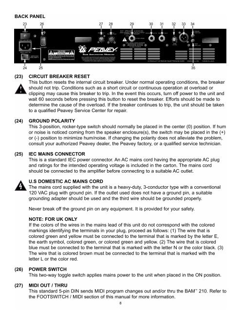
BACK PANEL<br />
23 26 27 28 29 30 31 32 33 34<br />
24 25 35<br />
(23) CIRCUIT BREAKER RESET<br />
This button resets the internal circuit breaker. Under normal operating conditions, the breaker<br />
should not trip. Conditions such as a short circuit or continuous operation at overload or<br />
clipping may cause this breaker to trip. In the event this occurs, turn off power to the unit and<br />
wait 60 seconds before pressing this button to reset the breaker. Efforts should be made to<br />
determine the cause of the overload. If the breaker continues to trip, the unit should be taken<br />
to a qualified <strong>Peavey</strong> Service Center for repair.<br />
(24) GROUND POLARITY<br />
This 3-position, rocker-type switch should normally be placed in the center (0) position. If hum<br />
or noise is noticed <strong>com</strong>ing from the speaker enclosure(s), the switch may be placed in the (+)<br />
or (-) position to minimize hum/noise. If changing the polarity does not alleviate the problem,<br />
consult your authorized <strong>Peavey</strong> dealer, the <strong>Peavey</strong> factory, or a qualified service technician.<br />
(25) IEC MAINS CONNECTOR<br />
This is a standard IEC power connector. An AC mains cord having the appropriate AC plug<br />
and ratings for the intended operating voltage is included in the carton. The mains cord<br />
should be connected to the amplifier before connecting to a suitable AC outlet.<br />
U.S DOMESTIC AC MAINS CORD<br />
The mains cord supplied with the unit is a heavy-duty, 3-conductor type with a conventional<br />
120 VAC plug with ground pin. If the outlet used does not have a ground pin, a suitable<br />
grounding adapter should be used and the third wire should be grounded properly.<br />
Never break off the ground pin on any equipment. It is provided for your safety.<br />
NOTE: FOR UK ONLY<br />
If the colors of the wires in the mains lead of this unit do not correspond with the colored<br />
markings identifying the terminals in your plug, proceed as follows: (1) The wire that is<br />
colored green and yellow must be connected to the terminal that is marked by the letter E,<br />
the earth symbol, colored green, or colored green and yellow. (2) The wire that is colored<br />
blue must be connected to the terminal that is marked with the letter N or the color black. (3)<br />
The wire that is colored brown must be connected to the terminal that is marked with the<br />
letter L or the color red.<br />
(26) POWER SWITCH<br />
This two-way toggle switch applies mains power to the unit when placed in the ON position.<br />
(27) MIDI OUT / THRU<br />
This standard 5-pin DIN sends MIDI program changes out and/or thru the <strong>BAM</strong> <strong>210</strong>. Refer to<br />
the FOOTSWITCH / MIDI section of this manual for more information.<br />
8