

AT-3624TR/3648TR Installation Manual - Allied Telesis
AT-3624TR/3648TR Installation Manual - Allied Telesis
AT-3624TR/3648TR Installation Manual - Allied Telesis

Create successful ePaper yourself
Turn your PDF publications into a flip-book with our unique Google optimized e-Paper software.
Hardware <strong>Installation</strong><br />
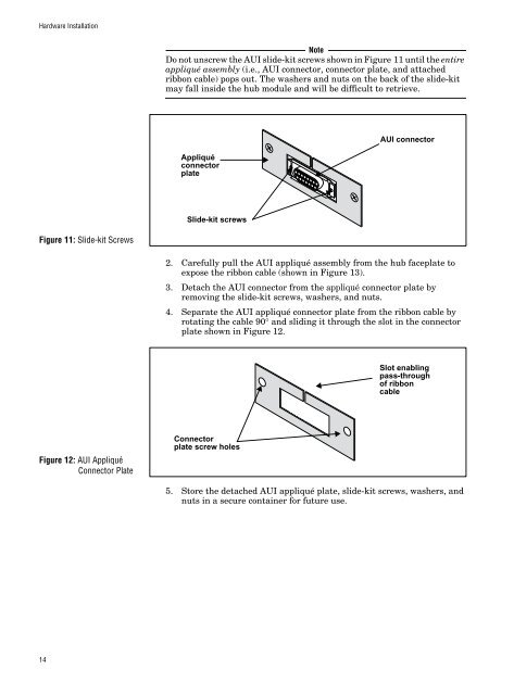
Note<br />
Do not unscrew the AUI slide-kit screws shown in Figure 11 until the entire<br />
appliqué assembly (i.e., AUI connector, connector plate, and attached<br />
ribbon cable) pops out. The washers and nuts on the back of the slide-kit<br />
may fall inside the hub module and will be difficult to retrieve.<br />
Appliqué<br />
connector<br />
plate<br />
AUI connector<br />
Slide-kit screws<br />
Figure 11: Slide-kit Screws<br />
2. Carefully pull the AUI appliqué assembly from the hub faceplate to<br />
expose the ribbon cable (shown in Figure 13).<br />
3. Detach the AUI connector from the appliqué connector plate by<br />
removing the slide-kit screws, washers, and nuts.<br />
4. Separate the AUI appliqué connector plate from the ribbon cable by<br />
rotating the cable 90° and sliding it through the slot in the connector<br />
plate shown in Figure 12.<br />
Slot enabling<br />
pass-through<br />
of ribbon<br />
cable<br />
Figure 12: AUI Appliqué<br />
Connector Plate<br />
Connector<br />
plate screw holes<br />
5. Store the detached AUI appliqué plate, slide-kit screws, washers, and<br />
nuts in a secure container for future use.<br />
14


![AT-8100L/8POE-E [Rev B] - Allied Telesis](https://img.yumpu.com/25714603/1/190x245/at-8100l-8poe-e-rev-b-allied-telesis.jpg?quality=85)


