

AT-3624TR/3648TR Installation Manual - Allied Telesis
AT-3624TR/3648TR Installation Manual - Allied Telesis
AT-3624TR/3648TR Installation Manual - Allied Telesis

Create successful ePaper yourself
Turn your PDF publications into a flip-book with our unique Google optimized e-Paper software.
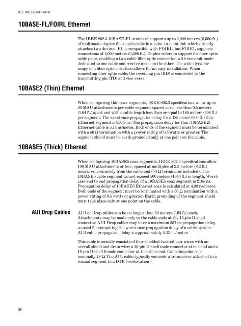
IEEE 802.3 Quick Primer<br />
10BASE-FL/FOIRL Ethernet<br />
10BASE2 (Thin) Ethernet<br />
The IEEE 802.3 10BASE-FL standard supports up to 2,000 meters (6,560 ft.)<br />
of multimode duplex fiber optic cable in a point-to-point link which directly<br />
attaches two devices. FL is compatible with FOIRL, but FOIRL supports<br />
connections of 1,000 meters (3,280 ft.). Duplex refers to support for fiber optic<br />
cable pairs, enabling a two-cable fiber optic connection with transmit mode<br />
dedicated to one cable and receive mode on the other. The wide dynamic<br />
range of a fiber optic interface allows for an easy installation. When<br />
connecting fiber optic cable, the receiving pin (RD) is connected to the<br />
transmitting pin (TD) and vice versa.<br />
10BASE5 (Thick) Ethernet<br />
When configuring thin coax segments, IEEE 802.3 specifications allow up to<br />
30 MAU attachments per cable segment spaced at no less than 0.5 meters<br />
(1.64 ft.) apart and with a cable length less than or equal to 185 meters (606 ft.)<br />
per segment. The worst case propagation delay for a 185 meter (606 ft.) thin<br />
Ethernet segment is 950.9 ns. The propagation delay for thin (10BASE2)<br />
Ethernet cable is 5.14 ns/meter. Both ends of the segment must be terminated<br />
with a 50 Ω termination with a power rating of 0.5 watts or greater. The<br />
segment shield must be earth grounded only at one point on the cable.<br />
When configuring 10BASE5 coax segments, IEEE 802.3 specifications allow<br />
100 MAU attachments or less, spaced at multiples of 2.5 meters (8.2 ft.)<br />
measured accurately from the cable end (50 Ω terminator included). The<br />
10BASE5 cable segment cannot exceed 500 meters (1640 ft.) in length. Worstcase<br />
end to end propagation delay of a 10BASE5 coax segment is 2165 ns.<br />
Propagation delay of 10BASE5 Ethernet coax is calculated at 4.33 ns/meter.<br />
Both ends of the segment must be terminated with a 50 Ω termination with a<br />
power rating of 0.5 watts or greater. Earth grounding of the segment shield<br />
must take place only at one point on the cable.<br />
AUI Drop Cables<br />
AUI or Drop cables can be no longer than 50 meters (164 ft.) each.<br />
Attachments may be made only to the cable ends at the 15-pin D-shell<br />
connector. AUI Drop cables may have a maximum 257 ns propagation delay,<br />
as used for computing the worst case propagation delay of a cable system.<br />
AUI cable propagation delay is approximately 5.13 ns/meter.<br />
This cable internally consists of four shielded twisted pair wires with an<br />
overall shield and drain wire; a 15-pin D-shell male connector at one end and a<br />
15-pin D-shell female connector at the other end. Cable impedance is<br />
nominally 78 Ω. The AUI cable typically connects a transceiver attached to a<br />
coaxial segment to a DTE (workstation).<br />
56


![AT-8100L/8POE-E [Rev B] - Allied Telesis](https://img.yumpu.com/25714603/1/190x245/at-8100l-8poe-e-rev-b-allied-telesis.jpg?quality=85)


