Mathcad - ee217projtodonew2.mcd
Mathcad - ee217projtodonew2.mcd
Mathcad - ee217projtodonew2.mcd

Create successful ePaper yourself
Turn your PDF publications into a flip-book with our unique Google optimized e-Paper software.
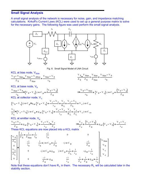
Small Signal Analysis<br />
A small signal analysis of the network is necessary for noise, gain, and impedance matching<br />
calculations. Kirkoff’s Current Laws (KCL) were used to set up a general purpose matrix to solve<br />
for the necessary gains. The following figure was used perform the small signal analysis.<br />
C µ<br />
Z S<br />
r b<br />
i bn I cn R L<br />
V S<br />
Z π<br />
g m *v π<br />
Z bias<br />
Z L<br />
v nRbias<br />
Z e<br />
v nRL<br />
Fig. 6: Small Signal Model of LNA Circuit<br />
KCL at bias node, V bias<br />
V S<br />
V bias V bias V nbias V bias V b<br />
Z S Z bias r b<br />
V S<br />
Z S<br />
V bias<br />
Z S<br />
V bias V bias V b<br />
Z bias r b<br />
KCL at base node, V b<br />
V bias V b<br />
V b V . c j. ω . C µ<br />
r b<br />
KCL at collector node, V c<br />
V b V . c j. ω . C µ g . m V b V e<br />
V b V e<br />
V b<br />
0<br />
Z π<br />
V c<br />
r o<br />
V e<br />
V c<br />
R L<br />
V c V L<br />
Z L<br />
V bias<br />
V b V . c j. ω . C µ<br />
r b<br />
V . c j. ω . C cs<br />
V b<br />
Z π<br />
V e<br />
V L<br />
V c V . b j. ω . C µ g . m V b V e<br />
Z L<br />
V c<br />
r o<br />
V e<br />
V c<br />
R L<br />
V c<br />
Z L<br />
V . c j. ω . C cs<br />
KCL at emitter node, V e<br />
V b V e<br />
g . m V b V e<br />
Z π<br />
V c<br />
r o<br />
V e<br />
V e<br />
Z e<br />
0<br />
These KCL equations are now placed into a KCL matrix<br />
V S<br />
Z S<br />
0<br />
V L<br />
Z L<br />
0<br />
1 1 1<br />
Z S Z bias r b<br />
1<br />
r b<br />
0<br />
0<br />
V e V e V b<br />
g . m V e V b<br />
Z e Z π<br />
1<br />
0<br />
0<br />
r b<br />
1<br />
j. ω . 1<br />
C µ<br />
j. ω .<br />
1<br />
C µ<br />
r b<br />
Z π<br />
Z π<br />
j. ω . C µ g m j. ω . 1 1<br />
1<br />
C µ<br />
g m<br />
Z L r o<br />
r o<br />
1<br />
1 1 1 1<br />
g m g m<br />
Z π r o Z e Z π r o<br />
Note that these equations don’t have R L in them. The necessary R L will be calculated later in the<br />
stability section.<br />
.<br />
V bias<br />
V b<br />
V c<br />
V e<br />
V e<br />
r o<br />
V c