Mathcad - ee217projtodonew2.mcd
Mathcad - ee217projtodonew2.mcd
Mathcad - ee217projtodonew2.mcd

Create successful ePaper yourself
Turn your PDF publications into a flip-book with our unique Google optimized e-Paper software.
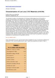
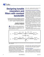
Optimal Source Impedance to Trade-Off Power and Noise<br />
The following method is a crude, but quick and relatively easy method for finding the optimal<br />
source impedance to trade-off power and noise. A more accurate method is discusses below<br />
but not implemented.<br />
Optimal Noise Source Impedance:<br />
Z n =r n +jx n ,<br />
NF=NF min<br />
Optimal Gain Source Impedance<br />
Z p =r p +jx p ,<br />
G=G max ,<br />
S 11 =0<br />
Constant S 11 contour<br />
Desired Source Impedance<br />
Z=r+jx<br />
S 11 =Desired Specification<br />
Fig. 26: Figure used to illustrade noise and power trade-off<br />
In the design of a low noise amplifier,LNA, or mixer driver stage there exists an optimal source<br />
source impedance to provide the maximum power transfer into the transistor and thus the<br />
maximum gain. There also exists an optimal source impedance, Z nopt , to provide the minimum<br />
noise figure for the circuit. At the maximum power source impedance, Z popt , the input is matched<br />
to the source impedance and no reflections occur. This is desirable, because the filters attached<br />
to designed for the LNA or mixer, are designed for a matched load impedance, but can tolerate a<br />
certain amount of deviation from it’s desired impedance. The amount of acceptable deviation is<br />
usually specified by the maximum return loss, or S 11 , the filter can handle. The routine below<br />
finds the source impedance to the LNA or mixer, which will provide the lowest noise figure and<br />
maximum gain, while maintaining a desired S 11 specification.<br />
The calculation is performed by drawing a straight line between the optimal noise and power<br />
source impedances and finding where it intersects the desired S 11 contour. This line intersects<br />
the contour at two points, so the point must be chosen, which is closet to the optimal noise<br />
source impedance. Sometimes, the desired S 11 specification is acheived at the optimal noise<br />
source impedance. In this case the optimal noise source impedance is chosen over the<br />
intersecting point. This calculation is not optimal in the truest sense, because the noise and<br />
power gain circles are not coencentric, but it serves as an good estimate to meet design criteria.