Mathcad - ee217projtodonew2.mcd
Mathcad - ee217projtodonew2.mcd
Mathcad - ee217projtodonew2.mcd

Create successful ePaper yourself
Turn your PDF publications into a flip-book with our unique Google optimized e-Paper software.
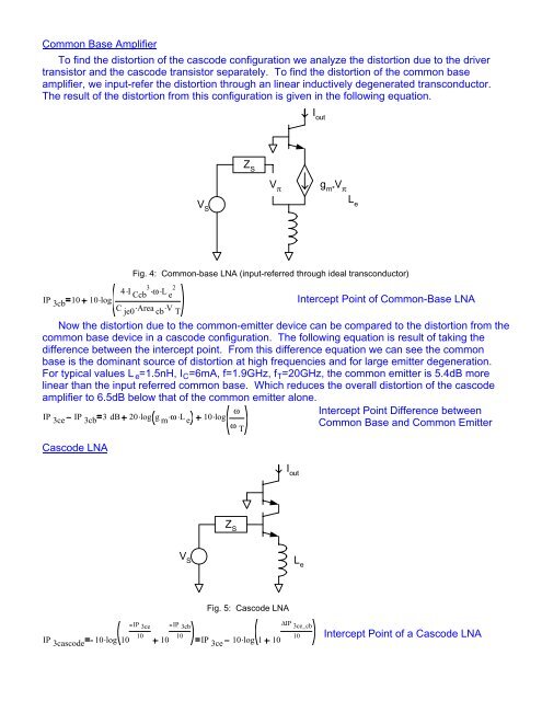
Common Base Amplifier<br />
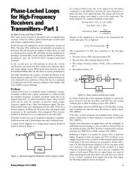
To find the distortion of the cascode configuration we analyze the distortion due to the driver<br />
transistor and the cascode transistor separately. To find the distortion of the common base<br />
amplifier, we input-refer the distortion through an linear inductively degenerated transconductor.<br />
The result of the distortion from this configuration is given in the following equation.<br />
I out<br />
V S<br />
Z S<br />
V π<br />
g m*<br />
V π<br />
L e<br />
IP 3cb 10<br />
10 log<br />
Fig. 4: Common-base LNA (input-referred through ideal transconductor)<br />
4I . 3. Ccb ω . 2<br />
L e<br />
C . je0 Area . cb V T<br />
. Intercept Point of Common-Base LNA<br />
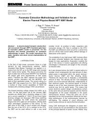
Now the distortion due to the common-emitter device can be compared to the distortion from the<br />
common base device in a cascode configuration. The following equation is result of taking the<br />
difference between the intercept point. From this difference equation we can see the common<br />
base is the dominant source of distortion at high frequencies and for large emitter degeneration.<br />
For typical values L e =1.5nH, I C =6mA, f=1.9GHz, f T =20GHz, the common emitter is 5.4dB more<br />
linear than the input referred common base. Which reduces the overall distortion of the cascode<br />
amplifier to 6.5dB below that of the common emitter alone.<br />
Intercept Point Difference between<br />
IP 3ce IP 3cb 3dB 20logg . . m ω . L e 10.<br />
log ω<br />
Common Base and Common Emitter<br />
Cascode LNA<br />
ω T<br />
V S<br />
Z S<br />
I out<br />
L e<br />
Fig. 5: Cascode LNA<br />
IP 3ce IP 3cb<br />
10 10<br />
IP 3cascode 10. log 10 10 IP 3ce 10.<br />
log 1 10<br />
∆IP 3ce_cb<br />
10<br />
Intercept Point of a Cascode LNA