Mathcad - ee217projtodonew2.mcd
Mathcad - ee217projtodonew2.mcd
Mathcad - ee217projtodonew2.mcd

You also want an ePaper? Increase the reach of your titles
YUMPU automatically turns print PDFs into web optimized ePapers that Google loves.
Optimizing Area and Current<br />
I C 0.006 Unitless Guesses at optimal bias current<br />
and device size<br />
N 50<br />
NF N, I C NF min N, I . C A,<br />
s<br />
Given<br />
I C<br />
> 0<br />
Bias Current Constraint<br />
N> 0<br />
Device Size Constraints<br />
G avail N, I . C A, s G goaldB<br />
IP 3 N, I . C A, Z nopt N, I . C A,<br />
s , f, ∆f IP 3goaldBm<br />
46.572<br />
P Minimize NF, N, I C P =<br />
7.277 . 10 3<br />
N opt P 1<br />
N opt 46.572<br />
I Copt<br />
> Available Power Gain Constraint<br />
> Intercept Point Constraints<br />
= Optimal Device Size<br />
P .<br />
2<br />
A<br />
I Copt = 7.277 mA Optimal Bias Current Size<br />
NF min N opt , I Copt , s = 0.84 dB<br />
Optimal Minimum Noise Figure<br />
, , , s , f, ∆f = 10 dBm Optimal Intercept Point<br />
IP 3 N opt , I Copt Z nopt N opt I Copt<br />
Z S N opt , I Copt , s = 62.211 5.063i ohm<br />
Optimal Source Impedance<br />
Z L N opt , I Copt , s = 110.436 61.585i ohm<br />
Optimal Load Impedance<br />
G avail N opt , I Copt , s = 13.5 dB<br />
Optimal Gain<br />
Package (Bonding Wire/ Bonding Pad) Deimbedding<br />
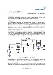
The actual impedance matching network is outside of the chip, but calculations for the desired<br />
source and load impedances were calculated for the device inside the chip. These internal<br />
source and load impedances must be transformed into the source and load impedances seen by<br />
the matching networks. To find these conversion equations we first write the equation for<br />
impedance seen by the device, Z S , given an impedance seen by the outside of the chip, Z Schip .<br />
Then we use this equation to solve for Z Schip in terms of Z S .<br />
Source Impedance Bonding Pad/Wire Deimbedding<br />
Z Schip<br />
L bond<br />
C pad<br />
Z S<br />
AMP<br />
Fig. 34: Circuit Used to Solve for Source Impedance Bonding Deimbedding