Mathcad - ee217projtodonew2.mcd
Mathcad - ee217projtodonew2.mcd
Mathcad - ee217projtodonew2.mcd

You also want an ePaper? Increase the reach of your titles
YUMPU automatically turns print PDFs into web optimized ePapers that Google loves.
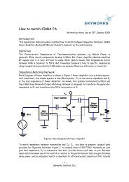
Gain Analysis<br />
Z2Γ( Z)<br />
Z<br />
Z<br />
G T<br />
Γ G<br />
, Γ L<br />
, S<br />
50 ohm<br />
50 ohm<br />
Available Power Gain<br />
1 Γ L<br />
2<br />
2<br />
S 2, 1<br />
Power<br />
2<br />
. . 1 Γ G<br />
1 S .<br />
22 ,<br />
Γ . L<br />
1 S .<br />
1, 1<br />
Γ G S 12<br />
Impedance to Reflection Coefficient Conversion<br />
. . Γ L<br />
Γ G<br />
,<br />
S 21 ,<br />
.<br />
2<br />
Transducer Gain<br />
G avail N, I C<br />
, s 10. log G T Z2Γ Z S N, I C<br />
, s , Z2Γ Z L N, I C<br />
, s , Sparam N, I C<br />
, s G avail N, I C<br />
, s = 14.166 dB<br />
15<br />
25<br />
Available Power Gain (dB)<br />
14<br />
13<br />
Available Power Gain (dB)<br />
20<br />
15<br />
12<br />
0 5 10 15 20<br />
10<br />
0 20 40 60 80 100<br />
Bias Current (mA)<br />
Available Power Gain (dB)<br />
Number of Devices in Parallel<br />
Available Power Gain (dB)<br />
Fig. 27: Power Gain vs. Bias Current<br />
Fig. 28: Power Gain vs. Device Size<br />
Distortion Analysis<br />
The distortion analysis routines were copied directly from the thesis of Keng Fong [2]. They are<br />
the most inaccurate portion of the design routine as they do not reflect the impact of the input<br />
matching network on distortion performance. From comparisions to simulations we see the results<br />
differ by 3-9dB. Future work will add the effects of the input matching network and bias circuitry.<br />
Low distortion in a low noise amplifier is important to prevent undesired signals from<br />
interfering with the desired signal. The most important measure of distortion performance is the<br />
third order intercept point. The scenario where third order distortion is important is when the<br />
receiving device is located a distance far from the transmitting device, and two devices are<br />
transmitting signals close to the device, spacing at frequencies ∆f and 2*∆f from the desired<br />
signal. Through third order distortion, the undesired signals, jammers, mix together to produce a<br />
signal in the desired band. To prevent this signal from degradation the performance of the<br />
receiver the low noise amplifier must be acceptably linear.<br />
A measure of the third order intercept point is used define at acceptable level of linearity. The<br />
third order intercept point is defined the as the jammer power required to make the amplitude of the<br />
jammer equal to the power of the undesired signal produced through third order intermodulation.<br />
This is shown graphically in the following figure.