RTS200 RFID Test Set - RFID Webshop
RTS200 RFID Test Set - RFID Webshop
RTS200 RFID Test Set - RFID Webshop

You also want an ePaper? Increase the reach of your titles
YUMPU automatically turns print PDFs into web optimized ePapers that Google loves.
All the common test files are usually together under the /common folder in the<br />
<strong>Test</strong>_<strong>Set</strong>up/<strong>Test</strong>_Characterisation or <strong>Test</strong>_setup/<strong>Test</strong>_Production directories. A test suite is<br />
usually composed of one or several common test files, defining all the standard parameters, being<br />
the parameters specific for this test suite, defined in the test suite file.<br />
It is important to understand that if a parameter is defined in the file corresponding to an individual<br />
test, the scope of this parameter will only be this particular test. All the previous and later tests<br />
make use of the parameter defined in the test suite.<br />
5 .3 Machine Interface Configuration<br />
There is an additional type of file that defines the interface between the <strong>RTS200</strong> and the machine<br />
where it runs in online mode. This file includes information about some special parameters to<br />
describe the operation of the hardware interface with the machine, that is, the polarities and timing<br />
of the signals sent from the machine to the <strong>RTS200</strong> to start the test or from the <strong>RTS200</strong> to the<br />
machine to signal the end of the test or its result. (See RTS HARDWARE MANUAL for a<br />
description of the hardware interface).<br />
This option has been included to provide flexible hardware interface, having in mind the diverse<br />
specification of the interfaces in different machines. The configuration parameters that have been<br />
introduced are described in ANNEX 2.<br />
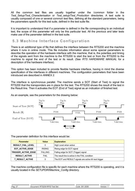
The interface is synchronous parallel. The machine sends a SOT (Start of <strong>Test</strong>) to signal the<br />
<strong>RTS200</strong> that the transponders are in place for the test. The <strong>RTS200</strong> shows the result of the test in<br />
the Result line. Then it activates the EOT (End of <strong>Test</strong>) signal as an indication of finished test.<br />
As an example, see the parameters for the drawing below:<br />
Start of <strong>Test</strong> (SOT)<br />
Tag In<br />
Place<br />
Tag In<br />
Place<br />
Tag In<br />
Place<br />
Tag In<br />
Place<br />
Result (R)<br />
End of <strong>Test</strong> (EOT)<br />
PASS FAIL PASS PASS<br />
Valid data Valid data Valid data Valid data<br />
<strong>Test</strong> Time<br />
The parameter definition for this interface would be:<br />
Parameter Value Explanation<br />
RESULT_FAIL_LEVEL 0 High Level when active<br />
EOT_ACTIVE_EDGE RISING Rising edge for EOT signal<br />
TRIGGER_ACTIVE_EDGE FALLING Falling edge for SOT (Trigger) signal<br />
RESULT_ACTIVE FAIL The result line is active in the FAIL condition<br />
T_RESULT_ACTIVE 0 The EOT and RESULT signals are active till next trigger<br />
The machine configuration file is specific for each machine where the <strong>RTS200</strong> is operating, and it is<br />
usually located in the SETUPDIR/Machine_Config directory.<br />
Pag: 27 Document: <strong>RTS200</strong> <strong>RFID</strong> <strong>Test</strong> <strong>Set</strong> Code: 001.0036 Version: 1